cc/td/doc/product/dsl_prod/6160
hometocprevnextglossaryfeedbacksearchhelp
PDF

Table Of Contents

Preparing for Installation

2.1 Safety Requirements

2.1.1 Safety Guidelines

2.1.2 Maintaining Safety with Electricity

2.1.3 Preventing Electrostatic Discharge Damage

2.1.4 General Maintenance Guidelines

2.2 Site Requirements

2.2.1 Environmental Requirements

2.2.2 Power Requirements

2.2.3 Rack-Mounting Requirements

2.3 Required Tools and Equipment

2.4 Unpacking the Cisco 6160 System

2.5 Verifying Contents

2.6 Inspecting for Damage


Preparing for Installation


This chapter provides the requirements that are necessary to prepare for the installation of the Cisco 6160 system.

This chapter contains the following sections:

Safety Requirements

Site Requirements

Required Tools and Equipment

Unpacking the Cisco 6160 System

Verifying Contents

Inspecting for Damage


Caution Before you begin the installation procedures, read the entire chapter for important information and safety warnings.

2.1 Safety Requirements

This section describes safety requirements for the Cisco 6160 system. Before you install the Cisco 6160 system, ensure that all the criteria in this section are met. This section describes the following safety requirements:

Safety Guidelines

Maintaining Safety with Electricity

Preventing Electrostatic Discharge Damage

General Maintenance Guidelines

2.1.1 Safety Guidelines

Before working on the equipment, be aware of standard safety guidelines and the hazards that are involved in working with electrical circuitry to prevent accidents. Adhere to the following cautions and warnings and those throughout the guide for safe and hazard-free installation.

Follow these guidelines to ensure general safety:

Keep the equipment area clear and dust-free during and after installation.

Keep tools away from walk areas where you and others could fall over them.

Do not wear loose clothing that could get caught in the chassis. Fasten ties or scarves and roll up shirt sleeves.

Wear safety glasses if you are working under conditions that might be hazardous to your eyes.

Do not perform any action that makes the equipment unsafe or creates a potential hazard to yourself or others.


Caution Before you start the installation procedures, read the entire chapter for important information and safety warnings.


Caution Proper ESD protection is required whenever you handle Cisco equipment. Installation and maintenance personnel should be properly grounded by means of grounding straps to eliminate the risk of ESD damage to the equipment. Equipment is subject to ESD damage whenever it is removed from the chassis.


Caution Be careful when you remove the standoff screws and reinsert the screws into the screw holes on the backplane so that the backplane circuitry does not become damaged.


Caution Installing the cards in the chassis with the power leads reversed can damage the line cards.


Caution If fuses are already installed in the fuse and alarm panel, remove them. You can replace the fuses after the system is installed. Do not power up the system while you install and connect the system.


Caution If the power connections are improperly made and power is applied while the cards are installed, the cards and chassis could be damaged.


Caution It is important that the chassis cooling fans run continuously.


Caution Any card that is only partially connected to the backplane can disrupt system operation.

Warning This warning symbol means danger. You are in a situation that could cause bodily injury. Before you work on any equipment, be aware of the hazards involved with electrical circuitry and be familiar with standard practices for preventing accidents. To see translations of the warnings that appear in this publication, refer to the Regulatory Compliance and Safety Information document that accompanied this device.

Waarschuwing

Dit waarschuwingssymbool betekent gevaar. U verkeert in een situatie die lichamelijk letsel kan veroorzaken. Voordat u aan enige apparatuur gaat werken, dient u zich bewust te zijn van de bij elektrische schakelingen betrokken risico's en dient u op de hoogte te zijn van standaard maatregelen om ongelukken te voorkomen. Voor vertalingen van de waarschuwingen die in deze publicatie verschijnen, kunt u het document Regulatory Compliance and Safety Information (Informatie over naleving van veiligheids- en andere voorschriften) raadplegen dat bij dit toestel is ingesloten.

Varoitus

Tämä varoitusmerkki merkitsee vaaraa. Olet tilanteessa, joka voi johtaa ruumiinvammaan. Ennen kuin työskentelet minkään laitteiston parissa, ota selvää sähkökytkentöihin liittyvistä vaaroista ja tavanomaisista onnettomuuksien ehkäisykeinoista. Tässä julkaisussa esiintyvien varoitusten käännökset löydät laitteen mukana olevasta Regulatory Compliance and Safety Information -kirjasesta (määräysten noudattaminen ja tietoa turvallisuudesta).

Attention

Ce symbole d'avertissement indique un danger. Vous vous trouvez dans une situation pouvant causer des blessures ou des dommages corporels. Avant de travailler sur un équipement, soyez conscient des dangers posés par les circuits électriques et familiarisez-vous avec les procédures couramment utilisées pour éviter les accidents. Pour prendre connaissance des traductions d'avertissements figurant dans cette publication, consultez le document Regulatory Compliance and Safety Information (Conformité aux rčglements et consignes de sécurité) qui accompagne cet appareil.

Warnung

Dieses Warnsymbol bedeutet Gefahr. Sie befinden sich in einer Situation, die zu einer Körperverletzung führen könnte. Bevor Sie mit der Arbeit an irgendeinem Gerät beginnen, seien Sie sich der mit elektrischen Stromkreisen verbundenen Gefahren und der Standardpraktiken zur Vermeidung von Unfällen bewußt. Übersetzungen der in dieser Veröffentlichung enthaltenen Warnhinweise finden Sie im Dokument Regulatory Compliance and Safety Information (Informationen zu behördlichen Vorschriften und Sicherheit), das zusammen mit diesem Gerät geliefert wurde.

Avvertenza

Questo simbolo di avvertenza indica un pericolo. La situazione potrebbe causare infortuni alle persone. Prima di lavorare su qualsiasi apparecchiatura, occorre conoscere i pericoli relativi ai circuiti elettrici ed essere al corrente delle pratiche standard per la prevenzione di incidenti. La traduzione delle avvertenze riportate in questa pubblicazione si trova nel documento Regulatory Compliance and Safety Information (Conformitā alle norme e informazioni sulla sicurezza) che accompagna questo dispositivo.

Advarsel

Dette varselsymbolet betyr fare. Du befinner deg i en situasjon som kan føre til personskade. Før du utfører arbeid på utstyr, må du vare oppmerksom på de faremomentene som elektriske kretser innebærer, samt gjøre deg kjent med vanlig praksis når det gjelder å unngå ulykker. Hvis du vil se oversettelser av de advarslene som finnes i denne publikasjonen, kan du se i dokumentet Regulatory Compliance and Safety Information (Overholdelse av forskrifter og sikkerhetsinformasjon) som ble levert med denne enheten.

Aviso

Este símbolo de aviso indica perigo. Encontra-se numa situaįão que lhe poderá causar danos físicos. Antes de comeįar a trabalhar com qualquer equipamento, familiarize-se com os perigos relacionados com circuitos eléctricos, e com quaisquer práticas comuns que possam prevenir possíveis acidentes. Para ver as traduįões dos avisos que constam desta publicaįão, consulte o documento Regulatory Compliance and Safety Information (Informaįão de Seguranįa e Disposiįões Reguladoras) que acompanha este dispositivo.

ĄAdvertencia!

Este símbolo de aviso significa peligro. Existe riesgo para su integridad física. Antes de manipular cualquier equipo, considerar los riesgos que entraņa la corriente eléctrica y familiarizarse con los procedimientos estándar de prevenciķn de accidentes. Para ver una traducciķn de las advertencias que aparecen en esta publicaciķn, consultar el documento titulado Regulatory Compliance and Safety Information (Informaciķn sobre seguridad y conformidad con las disposiciones reglamentarias) que se acompaņa con este dispositivo.

Varning!

Denna varningssymbol signalerar fara. Du befinner dig i en situation som kan leda till personskada. Innan du utför arbete på någon utrustning måste du vara medveten om farorna med elkretsar och känna till vanligt förfarande för att förebygga skador. Se förklaringar av de varningar som förkommer i denna publikation i dokumentet Regulatory Compliance and Safety Information (Efterrättelse av föreskrifter och säkerhetsinformation), vilket medföljer denna anordning.


Warning Before opening the chassis, disconnect the telephone-network cables to avoid contact with telephone-network voltages.


Warning Do not work on the system or connect or disconnect cables during periods of lightning activity.


Warning Read the installation instructions before you connect the system to its power source.


Warning Before working on a chassis or working near power supplies, unplug the power cord on AC units; disconnect the power at the circuit breaker on DC units.


Warning To prevent bodily injury when mounting or servicing this unit in a rack, you must take special precautions to ensure that the system remains stable. The following guidelines are provided to ensure your safety:

This unit should be mounted at the bottom of the rack if it is the only unit in the rack.

When mounting this unit in a partially filled rack, load the rack from the bottom to the top with the heaviest component at the bottom of the rack.

If the rack is provided with stabilizing devices, install the stabilizers before mounting or servicing the unit in the rack.


Warning The ports labeled "Ethernet," "10BaseT," "Token Ring," "Console," and "AUX" are safety extra-low voltage (SELV) circuits. SELV circuits should only be connected to other SELV circuits. Because the BRI circuits are treated like telephone-network voltage, avoid connecting the SELV circuit to the telephone network voltage (TNV) circuits.


Warning Class 1 laser product.


Warning Do not stare into the beam or view it directly with optical instruments.


Warning This unit is intended for installation in restricted access areas. A restricted access area is where access can only be gained by service personnel through the use of a special tool, lock and key, or other means of security, and is controlled by the authority responsible for the location.


Warning When installing the unit, always make the ground connection first and disconnect it last.


Warning This equipment is to be installed and maintained by service personnel only as defined by AS/NZS 3260 Clause 1.2.14.3 Service Personnel.


Warning A readily accessible two-poled disconnect device must be incorporated in the fixed wiring.


Warning To reduce the risk of fire, use only No. 26 AWG or larger telecommunication line cord.


Warning Never defeat the ground conductor or operate the equipment in the absence of a suitably installed ground conductor. Contact the appropriate electrical inspection authority or an electrician if you are uncertain that suitable grounding is available.


Warning During this procedure, wear grounding wrist straps to avoid ESD damage to the card. Do not directly touch the backplane with your hand or any metal tool, or you could shock yourself.


Warning Use copper conductors only.


Warning Blank faceplates and cover panels serve three important functions: they prevent exposure to hazardous voltages and currents inside the chassis; they contain electromagnetic interference (EMI) that might disrupt other equipment; and they direct the flow of cooling air through the chassis. Do not operate the system unless all cards, faceplates, front covers, and rear covers are in place.


Warning Only trained and qualified personnel should be allowed to install, replace, or service this equipment.


Warning Connect the unit only to DC power source that complies with the Safety Extra-Low Voltage (SELV) requirements in IEC 60950 based safety standards.


Warning Do not use this product near water; for example, near a bathtub, washbowl, kitchen sink or laundry tub, in a wet basement, or near a swimming pool.


Warning Never install telephone wiring during an electrical storm.


Warning Never install telephone jacks in wet locations unless the jack is specifically designed for wet locations.


Warning Never touch uninsulated telephone wires or terminals unless the telephone line has been disconnected at the network interface.


Warning Use caution when installing or modifying telephone lines.


Warning Avoid using a telephone (other than a cordless type) during an electrical storm. There may be a remote risk of electric shock from lightning.


Warning Do not use a telephone to report a gas leak in the vicinity of the leak.


Warning Ultimate disposal of this product should be handled according to all national laws and regulations.


Warning To prevent personal injury or damage to the chassis, never attempt to lift or tilt the chassis using the handles on the port adapters; these types of handles are not designed to support the weight of the unit. Lift the unit only by grasping the chassis underneath its lower edge.


Warning This equipment needs to be grounded. Use a green and yellow 14 AWG ground wire to connect the host to earth ground during normal use.


Warning This is a Class A product based on the standard of the Voluntary Control Council for Interference by Information Technology Equipment (VCCI). If this equipment is used in a domestic environment, radio disturbance may arise. When such trouble occurs, the user may be required to take corrective actions.


Warning The DS3 ports are not intended to be connected to cables that run outside the building where it is installed. For any connections outside the building, the DS3 ports must be connected to a network termination unit (NTU). NTU devices should comply with appropriate national safety standards such as UL 1950, CSA 950, EN 60950, IEC 950, and AS 3260.


Warning This product requires short-circuit (overcurrent) protection, to be provided as part of the building installation. Install only in accordance with national and local wiring regulations.


Warning High-performance devices on this card can get hot during operation. To remove the card, hold it by the faceplate and bottom edge. Allow the card to cool before touching any other part of it or before placing it in an antistatic bag.


Warning Do not reach into a vacant slot or chassis while you install or remove a module or a fan. Exposed circuitry could constitute an energy hazard.


2.1.2 Maintaining Safety with Electricity

Follow these guidelines when working on equipment that is powered by electricity:

Locate the emergency power-off switch for the room in which you are working. Then, if an electrical accident occurs, you can act quickly to turn off the power.

Disconnect all power by removing the fuses from the fuse and alarm panel before:

Installing or removing a chassis

Working near power supplies

Do not work alone if potentially hazardous conditions exist.

Never assume that power is disconnected from a circuit; always check the circuit.

Look carefully for possible hazards in your work area, such as moist floors, ungrounded power extension cables, frayed power cords, and missing safety grounds.

If an electrical accident occurs, proceed as follows:

Use caution; do not become a victim yourself.

Turn off power to the system.

If possible, send another person to get medical aid. Otherwise, assess the condition of the victim and then call for help.

Determine if the person needs rescue breathing or external cardiac compressions; then, take appropriate action.

2.1.3 Preventing Electrostatic Discharge Damage

Proper ESD protection is required whenever you handle Cisco equipment. ESD damage, which can occur when electronic cards or components are improperly handled, results in complete or intermittent failures. Use an antistatic strap when you handle any card or component.

Follow these guidelines to prevent ESD damage:

Always use an ESD ankle or wrist strap and ensure that the wrist strap makes good skin contact.

Connect the equipment end of the strap to the ESD jack on the front left side of the chassis, as shown in Figure 2-1.

When you install a component, use available ejector levers or captive installation screws to properly seat the bus connectors in the backplane or midplane. These devices prevent accidental removal, provide proper grounding for the system, and help ensure that bus connectors are properly seated.

When you remove a component, use available ejector levers or captive installation screws to release the bus connectors from the backplane or midplane.

Handle the I/O card by the edges only; avoid touching the printed circuit boards or connectors.

Avoid touching the printed circuit boards or connectors on the NI-2 cards or line cards.

Place a removed component board-side-up on an antistatic surface or in a static-shielding container. If you plan to return the component to the factory, immediately place it in a static-shielding container.

Avoid contact between the printed circuit boards and clothing. The wrist strap protects components from ESD voltages on the body only; ESD voltages on clothing can still cause damage.


Caution Periodically check the resistance value of the antistatic strap. Ensure that the measurement is between 1 and 10 megohms.

Figure 2-1 Cisco 6160 ESD Jack Location

2.1.4 General Maintenance Guidelines

This section covers the following topics:

Hot Swapping Cards

Hot Swapping Blower Trays and PEMs

Installation and Replacement Suggestions

2.1.4.1 Hot Swapping Cards

Hot swapping allows you to remove and replace cards without disconnecting the system power. The Cisco 6160 chassis supports hot swapping for the following cards:

Quad-port flexi ATU-C (4xflexi), quad-port STU-C (4xSDSL), octal-port DMT ATU-C (8xDMT), octal-port ITU-C (8xIDSL), and octal-port G.SHDSL SHTU-C (8xG.SHDSL) line cards—When the system detects that you have added or removed a line card, it automatically runs diagnostic and discovery routines and acknowledges the presence or absence of the line card. If you remove and replace a line card with one of the same type, the newly installed line card receives the same provisioning as the original card. The system resumes operation without any operator intervention.


Note Hot swapping line cards interrupts service for the subscribers assigned to that line card.


DS3+T1/E1 IMA, DS3/2DS3, OC-3c/2DS3, or OC-3c/OC-3c NI-2 cards—Hot swapping active NI-2 cards interrupts service for the entire system until the NI-2 card is replaced or until a redundant NI-2 takes over system operations. However, you can hot swap standby NI-2 cards without interrupting service.

2.1.4.2 Hot Swapping Blower Trays and PEMs

The following sections detail the hot swapping guidelines for the blower tray and power entry module (PEM).


Caution Only a trained technician should install and remove the PEM and blower tray.

2.1.4.2.1 Blower Trays

The blower tray supports hot swapping. Hot swapping allows you to remove the blower tray without disconnecting the system power. You do not need to power down the Cisco 6160 to replace the blower tray. However, if you must remove the blower tray from an operating Cisco 6160, replace it within five minutes. If that is not possible, power down the system to avoid thermal damage.

2.1.4.2.2 PEMs

The PEM is not hot swappable if there is only one PEM installed in the chassis. If you remove the only operating PEM from the chassis, power down the system before you begin. Removing the only operating PEM from the chassis will interrupt service for the entire system until you replace the PEM.

The PEM is hot swappable if there is a secondary PEM installed in the chassis. If the active PEM is removed, the standby PEM becomes the active PEM and the system continues to operate.

2.1.4.3 Installation and Replacement Suggestions

The following examples list recommended installation and replacement practices for the Cisco 6160 system cards.


Caution Any card that is only partially connected to the backplane can disrupt system operation.

Do not force the line card into its slot. This action can damage the pins on the backplane if they are not aligned properly with the line card.

Ensure that the line card is straight and not at an angle when you install the line card in the slot. Installing the line card at an angle can damage the line card. Use the guide rails to install the line card correctly.

Fully depress the ejector tabs to ensure that the line card connector mates with the backplane correctly. Firmly seat the line card in the slot.

Do not force the I/O card onto the chassis connectors. Ensure that the I/O card is straight and parallel to the chassis when you install the module onto the connectors. The pins on the connectors can be damaged if the I/O card is not installed correctly.

Firmly press on the I/O card to ensure that the connectors mate with the chassis correctly.

2.2 Site Requirements

This section describes requirements for the site at which the Cisco 6160 system is to be installed. Before you install the Cisco 6160 system, ensure that all the criteria in this section are met. This section includes the following information:

Environmental Requirements

Power Requirements

Rack-Mounting Requirements

2.2.1 Environmental Requirements

Proper operation of the Cisco 6160 system depends on a proper environment. Before you install the Cisco 6160 system, ensure that all the criteria in this section are met. This section describes the following environmental requirements:

Temperature, Altitude, and Humidity

Ventilation

Space

2.2.1.1 Temperature, Altitude, and Humidity

The Cisco 6160 system can tolerate a wide range of temperatures. Table 2-1 provides the Cisco recommendations for temperature, altitude, and humidity conditions in a central office (CO) environment.

Table 2-1 CO Operating Environment Requirements 

Environmental Specifications
Description

Temperature


Altitude

Humidity

41 to 104ēF (5 to 40ēC)—Operating
23 to 131ēF (-5 to 55ēC)—Short-term operating

-197 to 13,124 feet (-60 to 4,000 meters)

5 to 90% (noncondensing)


Warning To prevent the system from overheating, do not operate it in an area that exceeds the maximum recommended ambient temperature of 104°F (40°C).


2.2.1.2 Ventilation

The following practices ensure proper ventilation for the Cisco 6160 system:

Chassis placement—Leave one rack unit (RU) under each Cisco 6160 chassis for cabling needs and the intake plenum.

Blower tray installation—A blower tray must be installed in the Cisco 6160 chassis.

POTS splitter location—POTS splitters do not dissipate heat and should be positioned at the bottom of the rack.

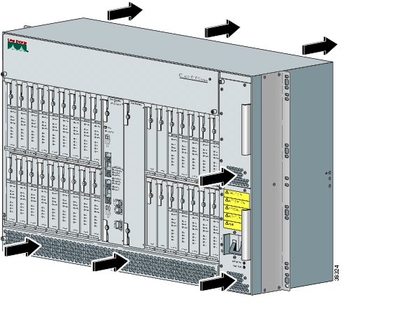
The main air intake vents are located at the bottom front of the chassis, as indicated in Figure 2-2. The intake vent for each PEM is located at the bottom of the PEM front panel. All air exhaust vents are located on the rear of the chassis at the top. Do not obstruct the intake and exhaust vents in any way.

Figure 2-2 Air Flow Through Intake and Exhaust Vents on the Chassis

2.2.1.3 Space

You can install a combination of these Cisco 6160 system components in a standard seven-foot rack:

Cisco 6160 chassis—A maximum of three chassis is allowed per rack.

Third-party POTS splitter—Required in a Cisco 6160 with POTS splitter configuration.

Depending on your configuration type, plan accordingly so that the CO rack accommodates your needs. Use Table 2-2 to calculate the rack space necessary for your Cisco 6160 system configuration. The total amount of rack space should not exceed 42 RUs. If your total configuration exceeds 42 RUs, either replan your configuration or use more than one rack to house the Cisco 6160 system components.

Table 2-2 Rack Space Calculation for Cisco 6160 System Configurations 

Line
Instructions
Calculation
Cisco 6160 with a POTS Splitter Configuration
1

Total number of Cisco 6160 chassis in the rack—Maximum is three chassis per rack (include subtending host and subtended node chassis)

 
2

Total number of third-party POTS splitters in the rack

 
3

Number of RUs required for each POTS splitter1

 
4

Multiply line 2 by line 3 to determine the total POTS splitter space requirement

 
5

Multiply 11 RUs by the total number of Cisco 6160 chassis on line 1

 
6

Multiply 1 RU by the total number of Cisco 6160 chassis on line 12

 
7
Add lines 4 through 6 to obtain the total number of RUs needed for a Cisco 6160 with a POTS splitter configuration.
 
Cisco 6160 Without a POTS Splitter Configuration
8

Total number of Cisco 6160 chassis in the rack—Maximum is three chassis per rack (include subtending host and subtended node chassis)

 
9

Multiply 11 RUs by the total number of Cisco 6160 chassis on line 8

 
10

Multiply 1 RU by the total number of Cisco 6160 chassis on line 82

 
11
Add lines 9 and 10 to obtain the total number of RUs needed for a Cisco 6160 without a POTS splitter configuration.
 

1 See the documentation that accompanied the third-party POTS splitter to determine the number of RUs required. One RU is equal to 1.75 inches (4.45 cm.).

2 One RU is recommended for cabling needs and the intake plenum.


2.2.2 Power Requirements

The CO power source or rectifier supplies external power to the system as -48VDC from the fuse and alarm panel. The nominal voltage is -48VDC, the minimum operating value is -40.5VDC, and the maximum operating value is -75VDC

Power connections from the fuse and alarm panel are wired to the power terminal block connectors on the Cisco 6160 backplane. The power terminal block connectors are located behind each corresponding PEM. The PWR 1 terminal block connector is for the primary PEM and the PWR 2 terminal block connector is for the secondary (redundant) PEM. Only one power connection is necessary for system operation.


Note Before you connect the system to a power source, verify that the power source is properly grounded and that it falls within the internal power supply rating.


The typical power required for your Cisco 6160 system will depend on your configuration type. Use Table 2-3 to calculate the power required for each of the Cisco 6160 system components and the total power required for the system.


Warning Only a DC power source that is isolated from AC mains with reinforced insulation, and that complies with the other safety extra-low voltage (SELV) requirements in UL1950, CSA 950 3rd Edition, EN 60950, and IEC950, can be connected to a Cisco 6160 system. This requirement ensures that in a catastrophic power source fault condition, hazardous voltages are not present on power terminals and connectors.


Table 2-3 Power Calculation for the Cisco 6160 System

Step
Instructions
Calculation
1

If you are using 8xIDSLs, multiply 5.5W by the total number of 8xIDSLs installed in the chassis.

 
2

If you are using 8xG.SHDSLs, multiply 16.5W by the total number of 8xG.SHDSLs installed in the chassis.

 
3

If you are using 8xDMTs, multiply 24W by the total number of 8xDMTs installed in the chassis.

 
4

If you are using 4xSDSLs, multiply 9W by the total number of 4xSDSLs installed in the chassis.

 
5

If you are using 4xflexis in G.lite mode, multiply 13W by the total number of 4xflexis (G.lite mode) installed in the chassis.

 
6

If you are using 4xflexis in DMT mode, multiply 17.5W by the total number of 4xflexis (DMT mode) installed in the chassis.

 
7

If you are using 4xflexis in CAP mode, multiply 13.5W by the total number of 4xflexis (CAP mode) installed in the chassis.

 
8

Multiply 33.5W by the number of NI-2 cards installed in the chassis.

 
9

Enter 60W for the PEM. Add 6W if a second PEM is installed in the chassis.

 
10

Enter 104W for the fan tray.

 
11

Add lines 1 through 10. This is the typical power required for the Cisco 6160.


2.2.3 Rack-Mounting Requirements


Warning Two people are required to lift the chassis. Grasp the chassis underneath the lower edge and lift with both hands. To prevent injury, keep your back straight and lift with your legs, not your back.


Warning To prevent bodily injury when mounting or servicing this unit in a rack, you must take special precautions to ensure that the system remains stable. The following guidelines are provided to ensure your safety:

—This unit should be mounted at the bottom of the rack if it is the only unit in the rack.

—When mounting this unit in a partially filled rack, load the rack from the bottom to the top with the heaviest component at the bottom of the rack.

—If the rack is provided with stabilizing devices, install the stabilizers before mounting or servicing the unit in the rack.


We recommend that you mount the Cisco 6160 system in a rack. Ensure that vertical hole spacing on the rack rails meets standard EIA-310-C requirements—1 inch (2.54 cm) spacing. All portions of the rack should be equal to or less than the NEBS maximum allowances of 12 inches (30.48 cm) in depth.

When you install the Cisco 6160 system in a rack, be sure to allow enough room to access the backplane of the unit for wiring and cabling purposes. The majority of the Cisco 6160 connectors are located on the backplane.

2.3 Required Tools and Equipment

Table 2-4 lists the tools and equipment you need to install and connect the Cisco 6160 system.

Table 2-4 Tool and Equipment Requirements Checklist 

Check
Tools and Equipment
 
Hardware Components and Cables
 

Cisco 6160 chassis, which will have the following components already installed:

Line cards (one or more types):

8xIDSL.

8xG.SHDSL.

8xDMT.

4xSDSL.

4xflexi.

One of the following NI-2 cards:

DS3+T1/E1 IMA.

DS3/2DS3.

OC-3c/2DS3 SMF1 or MMF2 .

OC-3c/OC-3c SMF or MMF.

One of the following I/O cards:

DS3/2DS3+8xT1 I/O card.

DS3/2DS3 I/O card.

Note The I/O card should ship with an EMI cover, screws, standoff screws, and washers.

PEM(s).

Blower tray.

Blank faceplates, as necessary.


Third-party POTS splitters can be installed in a Cisco 6160 with a POTS splitter configuration. Please verify the compatibility with your Cisco representative.


Telco cables with Champs connectors for the following configurations:

Cisco 6160 with a POTS splitter configuration.

Cisco 6160 to third-party POTS splitter connections.

Third-party POTS splitter to MDF3 connections.

Cisco 6160 without POTS splitter connections.

Cisco 6160 to MDF.

Note See Appendix B, "Cable and Port Mapping Specifications" for a port mapping table for the subscriber connections. Refer to the third-party POTS splitter documentation for cable specifics.


Wire for the following connections:

T1 or T1 IMA trunk—Industry standard T1 twisted-pair wire (use two-pair stock only).

T1 or T1 IMA subtend—RJ-48 to RJ-48 industry standard T1 twisted-pair wire (use two-pair stock only).

BITS4 clock interface—24 to 26 AWG5 twisted-pair wire.

Alarm contacts—24 to 26 AWG twisted-pair wire.

Ground the Cisco 6160 chassis—8 AWG or larger, green or green and yellow striped, copper solid or stranded.

Ground the POTS splitter, as necessary—Refer to the vendor documentation for wire specifications.

Cisco 6160 chassis power connections—12 AWG black and red copper solid or stranded.


Coaxial cable for a DS3 connection—Type 734A, type 735A, or equivalent.


Fiber cable for OC-3c connections—SMF or MMF, as appropriate.


7Console and auxiliary cables—Unshielded RJ-45 serial cable that complies with the EIA/TIA-232 standard and provides connection to a system console.


Ethernet connection—Cat 5 UTP6 or Cat 5 STP7 cable with an RJ-45 connector that complies with Ethernet standards.


Necessary equipment for ESD protection—Required whenever you handle Cisco equipment, which includes the chassis and modules.

 
Tools
 

No 1 3/16-inch flat-head screwdriver.


A Phillips-head screwdriver.


Wire stripper.


Wire-wrapping tool, optional.


Grounding lug crimping tool, as necessary.


Mounting screws—To mount the Cisco 6160 and POTS splitter to the rack.


Ring lugs (5/8-inch or 3/4-inch) for the grounding wire.

Note The hole in the ring lug should be large enough for the screw to pass through.


Metric measuring tape or ruler.


Marking pen.


Tie wraps, as necessary.

 
Software Components
 

Cisco IOS or CDM8 .

Note See Appendix A, "Technical Specifications" for minimum software and network management release requirements per Cisco 6160 chassis component.

1 SMF = single-mode fiber

2 MMF = multimode fiber

3 MDF = main distribution frame

4 BITS = building integrated timing supply

5 AWG = American Wire Gauge

6 UTP = unshielded twisted pair

7 STP = shielded twisted pair.

8 CDM = Cisco DSL Manager


Warning Only trained and qualified personnel should be allowed to install, replace, or service this equipment.


2.4 Unpacking the Cisco 6160 System

Each Cisco 6160 system chassis is securely packaged in a shipping box. The Cisco 6160 ships with the line cards and the NI-2 card(s) installed in the chassis.


Caution Proper ESD protection is required whenever you handle Cisco equipment. Installation and maintenance personnel should be properly grounded by means of grounding straps to eliminate the risk of ESD damage to the equipment. Equipment is subject to ESD damage whenever it is removed from the chassis.


Warning Two people are required to lift the chassis. Grasp the chassis underneath the lower edge and lift with both hands. To prevent injury, keep your back straight and lift with your legs, not your back.


To unpack the Cisco 6160 system, complete the following steps:


Step 1 Inspect the packing containers. If any damage or other signs of mishandling are evident, inform both the local freight carrier and Cisco before unpacking. Your freight carrier can provide you with the procedures necessary to file a claim for damages.

Step 2 Carefully open the box.

Step 3 Remove all packing material.

Step 4 Remove the chassis from the box.

Step 5 Carefully open the additional boxes and remove the packing material.

Step 6 Open the accessory kits and boxes that contain the cables, documentation, and management software. Do not use a knife to open these boxes.


2.5 Verifying Contents

To verify that all equipment, cables, documentation, and other items are received, compare the packing list to your shipment and to your order. If any items are missing or you need additional information, contact the Cisco Technical Assistance Center (TAC) at

800 553-2447

408 526-7209

tac@cisco.com

2.6 Inspecting for Damage

After you verify that all of the equipment is included, carefully examine the assemblies, cards, and cables for any damage resulting from shipping. If you suspect any damage from shipping, contact your local freight carrier for procedures on damage claims.

If you observe any physical defects in the items you ordered, obtain standard warranty service by delivering the defective part, accompanied by a copy of the dated proof-of-purchase, to the Cisco Systems Corporate Service Center or an Authorized Cisco Systems Service Center during the applicable warranty period. Contact the Cisco TAC for the location of your nearest service center.

See the back of the title page for the Cisco Systems warranty information for hardware and software products.


hometocprevnextglossaryfeedbacksearchhelp

Posted: Thu Feb 24 12:53:28 PST 2005
All contents are Copyright © 1992--2005 Cisco Systems, Inc. All rights reserved.
Important Notices and Privacy Statement.