|
|

Table Of Contents
Connector and Pinout Specifications
C.2 Cisco 6160 Terminal Block Connectors
C.3 DS3/2DS3+8xT1 IMA I/O Card Wire-Wrap Pin Mapping
C.4 DS3/2DS3 I/O Card Wire-Wrap Pin Mapping
C.5 Pinouts for the DS3/2DS3+8xT1 IMA I/O Card RJ-48c Receptacles
C.6 Console and Auxiliary Ports
Connector and Pinout Specifications
This appendix provides information about connectors and pinouts for configuration of the Cisco 6160 system.
C.1 xDSL Connectors
The backplane of the Cisco 6160 chassis contains eleven Champ connectors which connect to the xTU-C twisted-pair subscriber data interface. This connection can be made by either of the following:
•
Through a POTS splitter for voice and data applications (Cisco 6160 with a POTS splitter configuration)
•
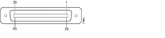
Figure C-1 shows connector pin locations for the xDSL Champ connectors. Pin locations are the same for all Champ connectors.
Figure C-1 xDSL Connector Pin Locations
C.2 Cisco 6160 Terminal Block Connectors
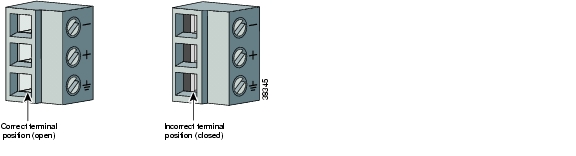
Use the terminal block connector to wire the Cisco 6160 to the power source on the fuse and alarm panel. The terminal block connector can also be used to ground the chassis. For more information on power connections and grounding procedures, see the appropriate installation chapter.
Figure C-2 shows the Cisco 6160 system power terminal block.
Figure C-2 Cisco 6160 Terminal Block Connector for Power and Grounding
C.3 DS3/2DS3+8xT1 IMA I/O Card Wire-Wrap Pin Mapping
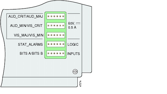
Figure C-3 shows a close-up of the wire-wrap pins.
Figure C-3 DS3/2DS3+8xT1 IMA I/O Card Wire-Wrap Pins Close-Up
Table C-1 maps the wire-wrap pins to the alarms supported by the NI-2 card through the Cisco 6160 backplane.
Table C-1 DS3/2DS3+8xT1 IMA I/O Card Wire-Wrap Pin Mapping
1
AUD_CRITICAL_CO6
AUD_MINOR_CO
VIS_MAJOR_CO
DOOR_ALARM
RX7 _BITS_TIPA
(NI-2 slot 11)2
AUD_CRITICAL_NO8
AUD_MINOR_NO
VIS_MAJOR_NO
STATION_3
RX_BITS_RINGA
(NI-2 slot 11)3
AUD_CRITICAL_NC9
AUD_MINOR_NC
VIS_MAJOR_NC
STATION_4
RX_BITS_GND10 /GND
4
AUD_MAJOR_CO
VIS_CRITICAL_CO
VIS_MINOR_CO
STATION_5
RX_BITS_TIPB
(NI-2 slot 10)5
AUD_MAJOR_NO
VIS_CRITICAL_NO
VIS_MINOR_NO
ACO11 _NO
RX_BITS_RINGB
(NI-2 slot 10)6
AUD_MAJOR_NC
VIS_CRITICAL_NC
VIS_MINOR_NC
STATION_CO/GND
RX_BITS_GND/GND
1 AUD = audible
2 CRIT = critical
3 MAJ = major
4 MIN = minor
5 VIS = visible
6 CO = common
7 RX = receive
8 NO = normally open
9 NC = normally closed
10 GND = ground
11 ACO = alarm cutoff
Note
The BITS pins on Cisco 6160 DS3/2DS3+8xT1 IMA I/O card are slot specific. BITS_A pins are assigned to slot 11 and BITS_B pins are assigned to slot 10. Each BITS clock input is independent and terminated at 100 ohms.C.4 DS3/2DS3 I/O Card Wire-Wrap Pin Mapping
Table C-2 maps the wire-wrap pins to the alarms supported by the NI-2 card through the Cisco 6160 backplane.
Note
The BITS pins on Cisco 6160 DS3/2DS3 I/O card are slot specific. BITS_A pins are assigned to slot 11 and BITS_B pins are assigned to slot 10. Each BITS clock input is independent and terminated at 100 ohms.C.5 Pinouts for the DS3/2DS3+8xT1 IMA I/O Card RJ-48c Receptacles
The RJ-48c receptacles are used for a T1 or T1 IMA configuration. Table C-3 shows the pin assignments for the receptacles.
Table C-3 Pin Assignments for the RJ-48c Receptacles
1
Receive ring
2
Receive tip
3
No connection
4
Transmit ring
5
Transmit tip
6
No connection
7
No connection
8
No connection
C.6 Console and Auxiliary Ports
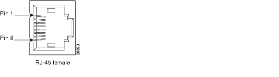
The console and auxiliary ports, which are two identical serial EIA/TIA-232 ports, use RJ-45 receptacle connectors on the NI-2 card faceplate. Table C-4 shows the pin assignments, and Figure C-4 shows an RJ-45 receptacle connector.
Table C-4 Pin Assignments for the NI-2 Card Console and Auxiliary Receptacles
1
RTS
2
DTR
3
TXD
4
GND
5
GND
6
RXD
7
DSR
8
CTS
Figure C-4 NI-2 Card Console and Auxiliary Receptacle
C.7 Ethernet Port
The Ethernet port, a 10BaseT interface with an RJ-45 receptacle connector, is on the NI-2 card faceplate. It is used to connect the Cisco 6160 to the management station, a Sun SPARCstation running Cisco DSL Manager (CDM) software. Table C-5 shows the pin assignments, and Figure C-5 shows an NI-2 card Ethernet connector.
Table C-5 Pin Assignments for the NI-2 Card Management Ethernet Connector
1
TX+
2
TX-
3
RX+
4
Unused
5
Unused
6
RX-
7
Unused
8
Unused
Figure C-5 NI-2 Card Management Ethernet Connector
![]()
![]()
![]()
![]()
![]()
![]()
![]()
![]()
Posted: Thu Feb 24 12:58:47 PST 2005
All contents are Copyright © 1992--2005 Cisco Systems, Inc. All rights reserved.
Important Notices and Privacy Statement.