|
|

Table Of Contents
Cabling the Line Ports and Completing the Installation
Connecting the line ports to the network
How to Configure the GBE Interface Parameters
How to Cable the GBE Line Interface Ports
Information About Cascaded Systems
How to Install a Cascaded System
CLI Commands for Cascaded Systems
How to Load and Activate a Service Control Application
Cabling the Line Ports and Completing the Installation
This chapter provides instructions for cabling the Gigabit Ethernet ports for both one and two SCE 2000 topologies, and for configuring Gigabit Ethernet (GBE) interface parameters. In a topology utilizing two SCE 2000 s (cascade), this includes the cascade ports as well as the line ports.
Note
When installing a cascaded system, it is extremely important to follow the sequence of procedures outlined in the section How to Install a Cascaded System.
Note
•
•
•
Connecting the line ports to the network
•
•
Cabling Diagrams
Before beginning, find the appropriate cabling diagram for the topology in your installation:
•
–
–
–
•
–
Note
Single Link: Inline Topology
In the inline topology, the SCE 2000 resides physically on the GBE (Gigabit Ethernet) link between the subscribers, which are usually connected through either a BRAS (in DSL access), a PDSN (in wireless access), a CMTS (in the Cable access), or a switch or router aggregator (in other topologies), and the network, where the SCE 2000 usually connects to a router or layer 3 switch network element.
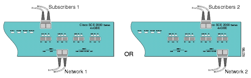
Figure 6-1 Cabling Diagram for Single Link Inline Topology
In the single link inline topology, either the first GBE link (first two ports) of the SCE 2000 or the second GBE link (third and fourth ports) can be used, as illustrated in the diagram above. The remaining pair of ports is unused.
Either port 1 or port 3 is used for connecting to the network element that is deployed on the subscriber side of the SCE 2000 while port 2 or port 4 is used for connecting to the network element that is deployed on the network side of the SCE 2000 .
Inline topology requires both Receive and Transmit fibers.
Single Link: Receive-only Topology
In this topology, an optical splitter resides physically on the GBE link that the SCE 2000 should monitor. The optical splitter is connected to the SCE 2000 via Rx links only.
In this topology, the traffic passes through the optical splitter, which splits traffic to the SCE 2000 .
Note
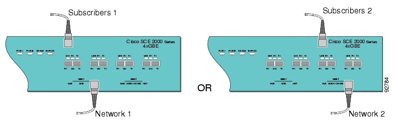
Figure 6-2 Cabling Diagram for Single SCE Platform Single Link Receive-only Topology
The single link receive-only topology cabling is similar to that for single link inline, in that either the first GBE link (first two ports) or the second GBE link (third and fourth ports) can be used, as illustrated in the diagram above. The remaining pair of ports is unused.
Either port 1 or port 3 is used for connecting to the network element that is deployed on the subscriber side of the SCE 2000 while port 2 or port 4 is used for connecting to the network element that is deployed on the network side of the SCE 2000 .
Dual Link: Single SCE 2000 Topologies
In this topology, one SCE 2000 is connected to two full duplex, GBE links. The SCE 2000 may be either inline, to support both monitoring and traffic control functionality, or receive-only for traffic monitoring functionality only.
When one SCE 2000 supports two links, the first two ports are connected to one link, while ports 3 and 4 are connected to the second link as follows;
•
•
•
•
As with the single link cabling, inline topologies require both Receive and Transmit fibers, while Receive-only systems use only Receive fibers.
Note
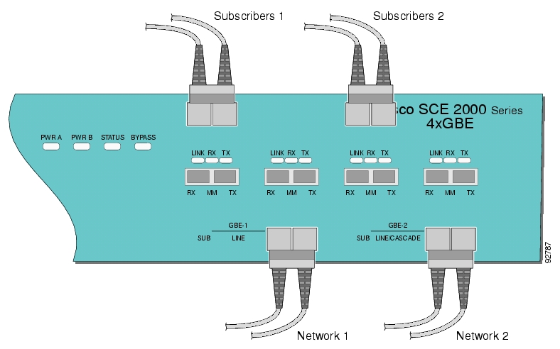
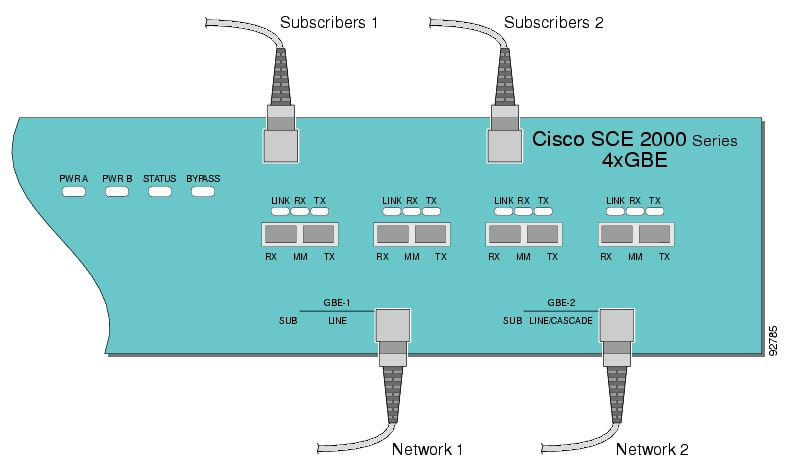
The following two diagrams illustrate the connections for dual links, with a single SCE 2000 deployed for both inline and receive-only topologies.
Figure 6-3 Cabling Diagram: Dual Link One SCE Platform Inline
Figure 6-4 Cabling Diagram: Dual Link One SCE Platform Receive-only
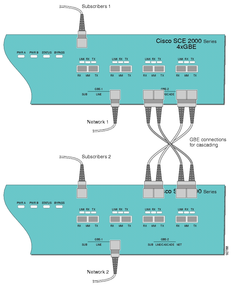
Dual Link: Two SCE 2000s Topology
In this topology, two SCE 2000s are connected to two full duplex, GBE links, providing full redundancy through cascading the two SCE 2000s. The SCE 2000s may be either inline, to support both monitoring and traffic control functionality, or receive-only for traffic monitoring functionality only.
Note
Note
When two SCE 2000s are used, the first two ports in each SCE 2000 are connected to the links, while ports 3 and 4 are the cascade ports that are used for communicating between the two SCE 2000s as follows:
SCE 2000 #1
•
•
•
•
SCE 2000 #2
•
•
•
•
Note
Inline topologies require connecting both Receive and Transmit fibers to the SCE 2000 . Cascade ports always require both Receive and Transmit fibers to be connected.
The following diagram illustrates the connections for a dual link, two SCE 2000 inline topology
Figure 6-5 Cabling Diagram: Dual Link Inline Topology Two Cascaded SCE Platforms
How to Configure the GBE Interface Parameters
By default, the SCE 2000 GBE line interface ports are configured with auto-negotiation disabled. The procedure for enabling auto-negotiation for the GBE line interface ports is explained in the following section.
Note
Note
copy running-config startup-config, and press Enter.
Note
SUMMARY STEPS
1.
2.
3.
4.
DETAILED STEPS
Step 1
The SCE 2000(config)# prompt appears.
Step 2
The SCE 2000(config if)# prompt appears.
Step 3
The SCE 2000(config if)# prompt appears.
Step 4
The SCE 2000(config)# prompt appears.
Repeat this procedure to configure auto-negotiation for the other GBE port interfaces as needed.
How to Cable the GBE Line Interface Ports
The following sections present the general procedure for cabling the GBE interface ports. Refer to Cabling Diagrams to find the appropriate cabling diagram for the topology of your system for the specific connections required.
Note
Class 1 laser. Avoid exposure to radiation and do not stare into open aperture.
Fiber Specifications
The following table presents the fiber specifications. The SCE 2000 may be ordered with either Multimode or Single Mode transceivers The transceiver type is indicated on the front panel under the ports. Note that both transceivers on any individual SCE 2000 are the same, either 850nm Multimode OR 1310nm Single Mode.
SUMMARY STEPS
1.
2.
DETAILED STEPS
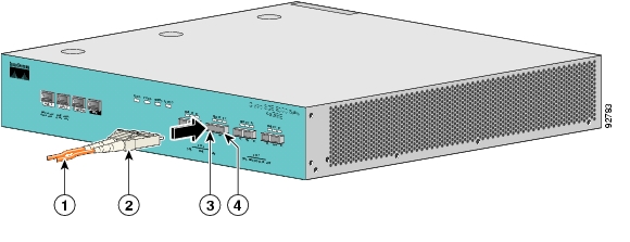
Step 1
Make sure to push on the connector until you hear a click, which indicates that the connector is fully inserted and secured in the receptacle. Always make sure that you insert the connector completely into the socket.
Figure 6-6 Cabling the GBE Interface
Step 2
If the link LED does not light, try removing the network cable plug and reinserting it firmly into the module socket.
Testing Connectivity: Examining Link LEDs and Counters to Verify that the Network Traffic is Reaching the Device
If the SCE 2000 platform has been powered up, test now to verify that connectivity has been established on all links. If the SCE 2000 platform is not powered up, perform this step after starting the SCE 2000 platform.
•
•
Examining the LEDs
The GBE Link LED must be green in order to verify that an active connection exists.
The GBE Rx and Tx LEDs (if flashing green) indicate that traffic is being received or transmitted by the SCE 2000 platform, respectively.
Note that in an inline topology, the Rx and Tx LEDs indicate that packets are being received/transmitted by the SCE 2000 platform.
In optical splitter topologies, the Rx LEDs are the sole indicators. The Tx LEDs do not "blink", since the Tx is not connected to the port in this topology.
How to View the Gigabit Ethernet Port Status
Step 1
This displays the port link and auto-negotiation status.
The following example displays a system response.
EXAMPLE:
SCE 2000#show interface GigabitEthernet 0/1
Auto negotiation configured: Enabled
Actual Status:
Link is on
Autonegotiation: Enabled
Bandwidth: 100000Kbps
Burst-size: 50000bytes
Again, auto-negotiation for bump-in-the-wire topology may be enabled or disabled. For receive-only topologies, using an external splitter, auto-negotiation must be disabled.
How to View the Gigabit Ethernet Counters
In an inline topology, you can monitor traffic via the platform counters for both the Rx and Tx connections. The counters increase, together with the increased number of packets that flow through the SCE 2000 for both Rx and Tx.
However, in external switch topologies, the counters for the Tx do not increment, that is, Tx does not have a function in monitoring traffic, as it is disconnected.
Step 1
This displays the GigabitEthernet counters. This command enables you to verify that traffic is taking place. You can see that the counters increase, together with the increased number of packets that flow through the SCE 2000 .
Again, in bump-in-the-wire topology, both the Rx and Tx counters apply as traffic monitors. For receive-only topologies, using an external splitter, only the Rx counters apply.
The following example shows the counters of the first Gigabit Ethernet interface.
SCE 2000#show interface GigabitEthernet 0/1 counters
In total octets: 100
In good unicast packets: 90
In good multicast packets: 0
In good broadcast packets: 10
In packets discarded: 0
In packets with CRC/Alignment error: 0
In undersized packets: 0
In oversized packets: 0
Out total octets: 93*2^32+1022342538
Out unicast packets: 858086051
Out non unicast packets: 0
Out packets discarded: 0
What to Do Next
You are now ready to continue to the next stage, How to Load and Activate a Service Control Application.
Information About Cascaded Systems
•
•
How to Install a Cascaded System
This section outlines the installation procedures for a redundant solution with two cascaded SCE 2000 platforms. Refer to the Cisco Service Control Engine (SCE) CLI Command Reference for details of the CLI commands.
When working with two SCE 2000 platforms with split-flow and redundancy, it is extremely important to follow this installation procedure.
SUMMARY STEPS
1.
2.
3.
4.
5.
6.
7.
8.
9.
10.
11.
DETAILED STEPS
Step 1
Step 2
Step 3
Step 4
Step 5
Use the show interface linecard 0 connection-modecommand.
Step 6
Step 7
Use the show interface linecard 0 link modecommand.
Step 8
Step 9
Step 10
Step 11
CLI Commands for Cascaded Systems
This section presents CLI commands relevant to the configuration and monitoring of a redundant system.
Use the following commands to configure and monitor a redundant system:
•
connection-mode•
[no] force failure-condition•
Show interface linecard 'number' connection-mode•
Show interface linecard 'number' physically-connected linksTopology-Related Parameters for Redundant Topologies
All four of the topology-related parameters are required when configuring a redundant topology.
•
–
–
•
•
•
How to Configure the Connection Mode
Use the following command to configure the connection mode, including the following parameters:
•
•
•
•
Step 1
EXAMPLE 1
Use the following command to configure the primary SCE platform in a two-SCE platform inline topology. Link 1 is connected to this SCE platform and the behavior of the SCE platform if a failure occurs is bypass.
SCE 2000(config if)# connection-mode inline-cascade physically-connected-links link-1
priority primary on-failure bypass
EXAMPLE 2
Use the following command to configure the SCE platform that might be cascaded with the SCE platform in Example 1. This SCE platform would have to be the secondary SCE platform, and Link 0 would be connected to this SCE platform, since Link 1 was connected to the primary. The connection mode would be the same as the first, and the behavior of the SCE platform if a failure occurs is also bypass.
SCE 2000(config if)# connection-mode inline-cascade physically-connected-links link-0
priority secondary on-failure bypass
How to Set the Link Mode
The SCE platform has an internal hardware card used to maintain the links even when the SCE platform fails. This hardware card has four possible modes of operation:
•
•
•
•
Normally, the link mode is selected by the SCE platform software according to the configured connection-mode. However, the link-modecommand can be used to enforce a specific desired mode. This may be useful when debugging the network, or in cases where we would like the SCE platform just to forward the traffic. (Note that this is only relevant to inline topologies even though the configuration is available also when in receive-only mode.)
The following link mode options are available:
•
•
This does not affect the redundancy states.
•
Sniffing is permitted to be configured for all links, only (use the all-links option).
•
Note the following recommendations and restrictions:
•
•
–
–
•
•
•
•
•
•
Step 1
Monitoring the System
Use the following commands to view the current connection mode and link mode parameters.
•
•
•
How to View the Current Connection Mode
Step 1
How to View the Current Link Mode
Step 1
How to View the Current Link Mappings
Step 1
How to Load and Activate a Service Control Application
The SCE 2000 platform provides the basic functionalities of Service Control analysis and enforcement. A Service Control solution requires that a Service Control application be loaded into the platform, to take advantage of the unique SCE platform capabilities.
Loading and activating an application includes the following stages:
•
•
•
The detailed procedure of how to perform these operations is not specified and described in this manual. For further details, refer to the following documentation:
•
•
![]()
![]()
![]()
![]()
![]()
![]()
![]()
![]()
Posted: Fri Aug 24 07:16:39 PDT 2007
All contents are Copyright © 1992--2007 Cisco Systems, Inc. All rights reserved.
Important Notices and Privacy Statement.