|
|

Table Of Contents
Information About Preparing to Install the SCE 2000 Platform
Information About Site Requirement Guidelines
Installing the SCE 2000 Platform
How to Install the SCE 2000 on a Workbench or Tabletop
Rack-Mounting a SCE 2000 Platform
How to Attach a Chassis Ground Connection
Removing and Replacing a Power Supply Unit
Information About the Power Supply
Powering Down the Power Supply Unit and Disconnecting Input Power
How to Remove the Power Supply Unit
How to Replace the Power Supply Unit
How to Reconnect AC-Input Power Supply Unit
How to Reconnect DC-Input Power Supply Unit
Removing and Replacing the Fan Module
Installation and Maintenance
This chapter explains how to install a SCE 2000 platform in a rack or in a general tabletop or workbench installation. Additionally, this chapter contains instructions for installing or replacing the power supply units and fan modules.
Before you install, operate, or service the system, read the Regulatory Compliance and Safety Information for the Cisco Service Control Engine . This guide contains important safety information you should know before working with the system.
•
Information About Preparing to Install the SCE 2000 Platform
•
•
•
Information About Preparing to Install the SCE 2000 Platform
Before installing your SCE 2000 platform, you should consider the power and cabling requirements that must be in place at your installation site, the equipment you need to install the platform, and the environmental conditions your installation site must meet to maintain normal operation. This section guides you through the process of preparing for your SCE 2000 platform installation and the installation in a rack. The section contains the following topics:
•
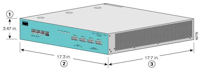
Figure 4-1 SCE 2000 Dimensions
Table 4-1 SCE 2000 Dimensions
Dimension
Measurement
Height
3.47 inches (9.5 cm)
Width
17.4 inches (4.43 cm)
Depth
18 inches (4.6 cm)
Weight
33 lb (15 kg)
Tools and Parts Required
The SCE 2000 chassis is fully assembled at the factory, including the application and software packages. No assembly is required. However, you need the following tools and equipment to install the SCE 2000 chassis and the rack-mount kit (if installing the SCE 2000 platform in a rack), fan modules, and power supplies:
•
•
•
•
•
Ring terminals must be UL approved and suitable for 12 AWG wire.
•
•
•
•
•
•
Information About Site Requirement Guidelines
The environmental monitoring functionality in the v protects the system and components from potential damage from over-voltage and over-temperature conditions. To ensure normal operation and to avoid unnecessary maintenance, plan your site configuration and prepare your site before installation. After installation, make sure the site maintains an ambient temperature of 41ΑF to 104ΑF (5ΑC to 40ΑC) with short term temperatures ranging from 23ΑF to 131ΑF (-5ΑC to 55ΑC), and keep the area around the SCE 2000 chassis free from dust.
Planning a proper location for the SCE 2000 and the layout of your equipment rack or wiring closet is essential for successful system operation. Equipment placed too close together or inadequately ventilated can cause system over-heating. In addition, chassis panels made inaccessible by poor equipment placement can make system maintenance difficult.
•
Airflow
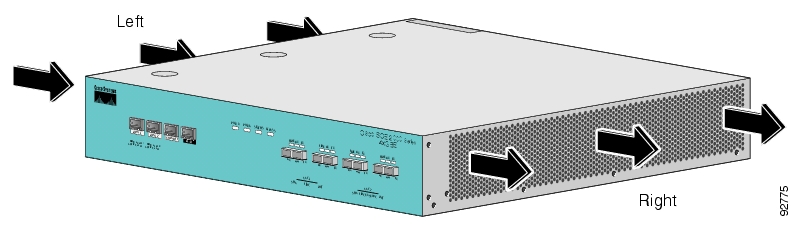
Figure 4-2 Airflow Through the SCE 2000
When you plan the location and layout of your equipment rack or wiring closet you need to consider how air flows though your system. The SCE 2000 draws cooling air in through the intake vents on the left side of the chassis, moves the air across the internal components, and out through the right side and rear panel of the chassis. The above figure illustrates the airflow through the SCE 2000 .
Note
Site Requirements
The following tables contain the site requirement specifications for the SCE 2000 .
*Short term is defined as not more than 96 consecutive hours, not more than 15 days in one year. 360 hours total in any given year, but no more than 15 occurrences in a one-year period.
For more complete information regarding safety and regulatory compliance, refer to the Regulatory Compliance and Safety Information for the Cisco Service Control Engine document.
The DC-powered SCE 2000 should be installed in a Restricted Access Location only.
Installing the SCE 2000 Platform
The SCE 2000 operates as either a tabletop or a rack-mounted unit. A rack-mounting kit is included with the SCE 2000 when it is shipped from the factory. The kit provides the hardware needed (see SCE 2000 Component List ) to mount the SCE 2000 in either of two types of standard 19-inch equipment rack:
•
•
If you are not rack-mounting your SCE 2000 , place it on a sturdy tabletop or workbench. A rubber feet kit is included for tabletop installations.
This section provides instructions for the physical installation of the SCE 2000 platform, including how to install the SCE 2000 in a rack, how to install the SCE 2000 on a tabletop or workbench, and how to properly ground the SCE 2000 platform. The section contains the following topics:
•
•
•
Installation Precautions
The router should already be in the area where you will install it, and your installation location should already be determined. If not, see Information About Site Requirement Guidelines and the Site Preparation and Safety Guide .
When installing the SCE 2000 , please observe the following conditions:
•
•
•
•
•
How to Install the SCE 2000 on a Workbench or Tabletop
You can install the SCE 2000 platform on any flat surface as long as the surface is large enough for the SCE 2000 (see the table in ), and allows for adequate airflow/ventilation around the sides of the SCE 2000 , as described in the Installation Precautions. When installing the SCE 2000 on a workbench or tabletop or in a rack, ensure that the surface is clean and in a safe location.
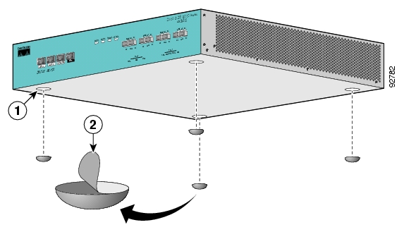
Figure 4-3 Installing the System on a Flat Surface
SUMMARY STEPS
1.
2.
3.
4.
5.
DETAILED STEPS
Step 1
Step 2
Step 3
There are four marked locations, indicating where to affix the rubber feet (see figure above).
Step 4
Step 5
Remember to check for proper ventilation. Allow at least 2 inches (5 cm) on each side for proper ventilation and 5 inches (12.7 cm) at the back for ventilation.and power cord clearance.
What to Do Next
Proceed to section, How to Attach a Chassis Ground Connection to continue the installation.
Rack-Mounting a SCE 2000 Platform
You can mount the SCE 2000 platform to a 19" rack. There are two standard types of equipment racks, and the appropriate brackets for each are provided in the enclosed kit.
•
•
The SCE 2000 mounts to the two front rack posts with brackets that attach to the front of the SCE 2000 The inside width between the two posts or mounting strips (left and right) must be at least 17.3 inches (44 cm).
Note
Because the inlet and exhaust ports (vents) for cooling air are located at both sides of the chassis, respectively, multiple SCE 2000 s can be stacked in a rack with no vertical clearance.
•
•
•
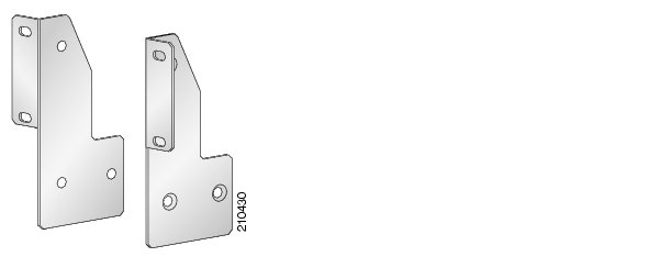
How to Attach the Brackets to the SCE 2000
Before installing the SCE 2000 in the rack, you must first install an appropriate rack-mount bracket on each side of the front of the SCE 2000 , as illustrated in the following figure. See Tools and Parts Required for a listing of the parts and tools required for installing the rack-mount.
SUMMARY STEPS
1.
2.
3.
DETAILED STEPS
Step 1
Step 2
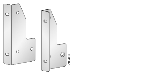
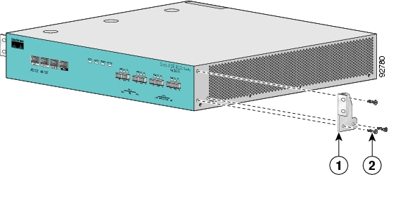
Figure 4-6 Attaching the Mounting Brackets (4-post)
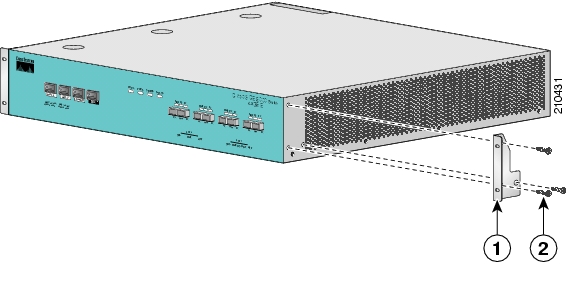
Figure 4-7 Attaching the Mounting Brackets (2-post)
Step 3
This completes the steps for attaching the rack-mount brackets to the SCE 2000 .
If mounting the SCE 2000 in a rack with only two posts, skip to How to Mount the System to the Rack.
If mounting the SCE 2000 in a rack with four posts, proceed to the next step to attach the crossrail supports to the rack.
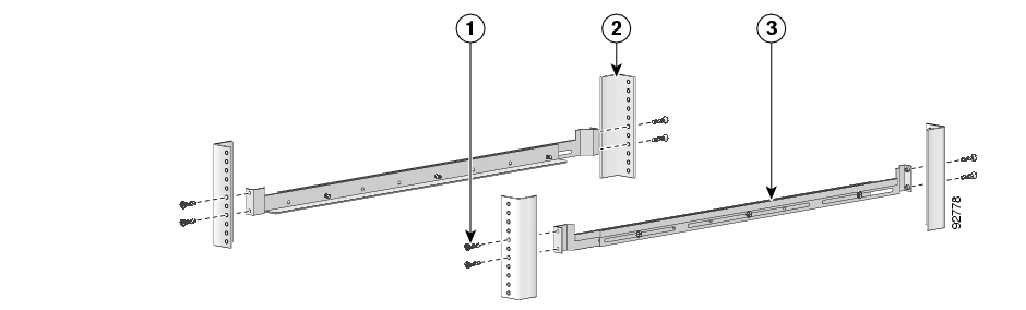
How to Attach the Crossrail Supports to the Rack
When mounting in a rack with four posts (front and back) the two crossrail supports are mounted one on each side of the rack. The SCE 2000 then slides into these crossrails, which support the weight of the unit.
Note
SUMMARY STEPS
1.
2.
3.
4.
5.
DETAILED STEPS
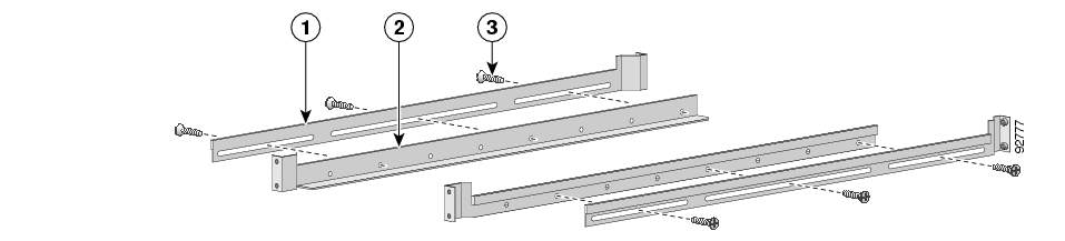
Step 1
Make sure that they are oriented so that both crossrails will support the SCE 2000 when they are attached to the rack.
Figure 4-8 Assembling the Slider Brackets
Step 2
Step 3
Step 4
Figure 4-9 Attaching the Crossrails to the Rack
Step 5
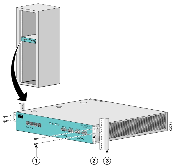
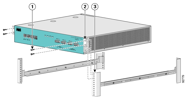
How to Mount the System to the Rack
When the appropriate mounting brackets are securely installed, the SCE 2000 can be installed into the rack.
SUMMARY STEPS
1.
2.
3.
4.
5.
DETAILED STEPS
Step 1
Step 2
Step 3
A rack with both front and back posts will have the crossrail supports installed. Slide the SCE 2000 onto these crossrails and push it all the way back.
Figure 4-10 Sliding the SCE Platform into the Rack
Step 4
Figure 4-11 Securing the SCE Platform to the Rack
Step 5
Note
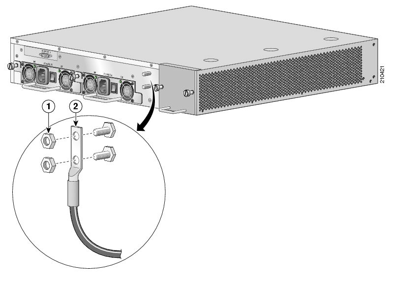
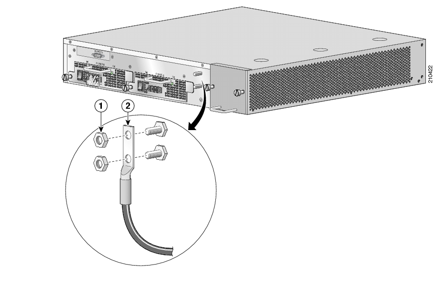
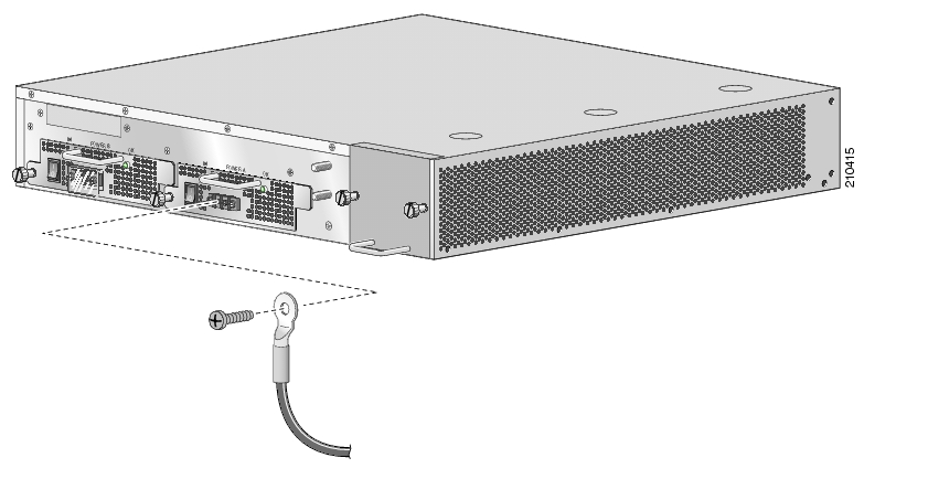
How to Attach a Chassis Ground Connection
Before you connect the power or turn on the power to the SCE 2000 platform, it is required that you provide an adequate chassis ground (protective earth) connection for the SCE 2000 chassis. A grounding kit is provided with each SCE 2000 .
Use the grounding kit to properly ground the SCE 2000 chassis (see SCE 2000 Component List for details).
Note
SUMMARY STEPS
1.
2.
3.
DETAILED STEPS
Step 1
Step 2
Step 3
The other side of the grounding cable must be connected to the site equivalent of the AC earth.
Figure 4-12 Grounding the Unit (AC)
Figure 4-13 Grounding the Unit (DC)
Removing and Replacing a Power Supply Unit
The procedures for removing and replacing the AC-input or DC-input power supply are explained in the following sections:
Do not remove or install modules without using appropriate anti-static guard measures. The SCE 2000 includes an anti-static wrist strap in the accessory kit. Attach the copper tape strap to an unpainted metal surface on the chassis. You may leave the strap connected to the chassis when your have finished.
Never install an AC power module and a DC power module in the same chassis.
•
•
•
Information About the Power Supply
The SCE 2000 is available in two power options:
•
•
The dual power supply units supply hot-swappable, redundant power. Redundant power is useful as a failover; if a situation occurs where one power supply is down (for instance, a power supply fails or a new power supply needs to be installed), the SCE 2000 can continue to run properly using the other power supply.
Each power supply has fans that cool the power supply unit. These fans also help to cool the internal components of the SCE 2000 , as they direct the air flow to the outside through vents in the rear of the power supply unit.
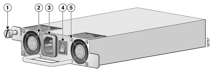
The faceplates of both power supplies have a handle, an on/off switch, and one captive installation screw. An AC-input power receptacle is available on the AC-input power supply and a DC-input terminal block is available on the DC-input power supply.
Note that the power supply units are asymmetrical, with a screw in only one corner of the unit. Therefore, both power supply units can be fastened only if both units are inserted in the proper orientation. This also prevents the accidental installation of one DC unit and one AC unit. (Refer to the following figures).
Figure 4-14 AC Unit Faceplate
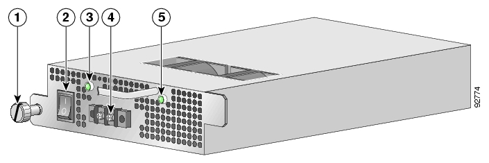
Figure 4-15 DC Unit Faceplate
The handle of the DC unit is at the top of the unit.
•
LEDs
The following LEDs are used to monitor the functioning of the power supply units:
•
–
–
•
–
On both the AC-input and DC-input power supplies, the IN LED iis used to monitor the voltages received by the platform from the power source. If the input voltages are within normal operating ranges, the green IN LED is illuminated. If the input voltages are above or below normal ranges, the IN LED is not illuminated.
On both the AC-input and DC-input power supplies, the OK LED is used to monitor the power supply DC output voltages used to power the platform. The normal operating ranges for the 12 VDC output voltage is between 11.9V and 12.1V. If the output voltages are within normal operating ranges, the green OK LED is illuminated. If the 12 VDC output voltages are above (more than 12.1V) or below (less than 11.9V) normal ranges, the OK LED is not illuminated.
The Power A and Power B LEDs on the front panel indicate whether the corresponding power supply unit is functioning normally.
Refer to the following tables for LED status information
Note
Power Supply Specifications
The following table lists the AC-input and DC-input power supply specifications for the SCE 2000 platform:
Note
Powering Down the Power Supply Unit and Disconnecting Input Power
The following sections describe how to remove power from an AC-input power supply and a DC-input power supply:
•
•
How to Power Down an AC-Input Power Supply
To power down an AC-input power supply to the SCE 2000 platform, complete the following steps:
Note
SUMMARY STEPS
1.
2.
3.
DETAILED STEPS
Step 1
Step 2
Step 3
What to Do Next
This completes the procedure for powering down an AC-input power supply unit on a SCE 2000 platform. Proceed to How to Remove the Power Supply Unit.
How to Power Down a DC-Input Power Supply Unit and Remove the DC-Input Leads
To power down a DC-input power supply to the SCE 2000 platform, complete the following steps:
Note
Note
SUMMARY STEPS
1.
2.
3.
4.
DETAILED STEPS
Step 1
Step 2
Step 3
Step 4
What to Do Next
This completes the procedure for powering down an DC-input power supply unit on a SCE 2000 platform. Proceed to How to Remove the Power Supply Unit.
How to Remove the Power Supply Unit
To remove the AC-input or DC-input power supply unit from the SCE 2000 platform, complete the following steps:
SUMMARY STEPS
1.
2.
DETAILED STEPS
Step 1
Step 2
How to Replace the Power Supply Unit
Note
SUMMARY STEPS
1.
2.
3.
4.
DETAILED STEPS
Step 1
Step 2
Step 3
Note
Step 4
Note
Reconnecting the Power
The following sections describe how to reconnect the AC or DC power:
•
•
How to Reconnect AC-Input Power Supply Unit
The following procedures explain how to reconnect an AC-input power to the SCE 2000 platform.
If you are reconnecting DC-input power, proceed to How to Reconnect DC-Input Power Supply Unit.
SUMMARY STEPS
1.
2.
3.
4.
5.
DETAILED STEPS
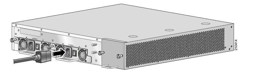
Step 1
Figure 4-16 Connecting the AC Power
Note
Note
Step 2
Step 3
Step 4
Step 5
How to Reconnect DC-Input Power Supply Unit
The following procedures explain how to reconnect a DC-input power to the SCE 2000 platform.
Before completing any of the following steps, and to prevent short-circuit or shock hazards, ensure that power is removed from the DC circuit. To ensure that all power to the power supply unit is OFF, locate the circuit breaker on the panel board that services the DC circuit, switch the circuit breaker to the OFF position, and tape the switch handle of the circuit breaker in the OFF position.
Note that the power to the relevant power supply unit should be off, not necessarily all power to the SCE 2000 platform. One DC-input power supply can be running when the other power supply is being removed or replaced.
Wiring should be done by a professional in accordance with state and local electrical codes.
SUMMARY STEPS
1.
2.
3.
4.
5.
6.
7.
8.
DETAILED STEPS
Step 1
Step 2
Step 3
Figure 4-17 Connecting the DC Power
Note
Note
Step 4
Step 5
Step 6
Step 7
Step 8
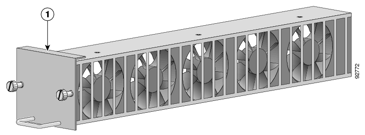
Fan Module Overview
The fan module provides cooling for the internal components. The fan drawer is a field-replaceable unit containing five fans, and is installed at the right rear of the SCE 2000 platform.
When a fan malfunctions, the fan module should be replaced as promptly as possible. Although it is possible for the unit to function for some time with one non-functioning fan, this is not optimal or recommended.
Figure 4-18 SCE Platform Fan Module
When a fan failure occurs, the environment monitor will send an error message to the console. An SNMP trap indicating that the fan is not functioning properly is also sent. Note that a fan failure is often audible.
•
Removing and Replacing the Fan Module
The following sections explain how to remove and replace a fan module in a SCE 2000 platform:
Do not remove or install modules without using appropriate anti-static guard measures. The SCE 2000 includes an anti-static wrist strap in the accessory kit. Attach the copper tape strap to an unpainted metal surface on the chassis. You may leave the strap connected to the chassis when your have finished.
•
How to Remove the Fan Module
Note
SUMMARY STEPS
1.
2.
DETAILED STEPS
Step 1
Step 2
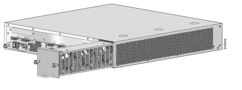
Replacing the Fan Module
SUMMARY STEPS
1.
2.
3.
4.
DETAILED STEPS
Step 1
Step 2
Step 3
Figure 4-19 Inserting the Fan Module
When inserting a fan module into the SCE 2000 platform, do not use unnecessary force; slamming the fan module into the chassis can damage the connectors on the rear of the module.
Step 4
Note
How to Replace the Battery
The SCE 2000 has a lithium battery on its main circuit board. When the battery loses its charge, call Cisco Technical Support to replace the battery.
Do not attempt to replace this battery yourself
There is danger of explosion if the lithium battery is incorrectly replaced. Replace only with the same or equivalent type recommended by the manufacturer. Dispose of used batteries according to the manufacturer's instructions.
![]()
![]()
![]()
![]()
![]()
![]()
![]()
![]()
Posted: Fri Aug 24 07:18:13 PDT 2007
All contents are Copyright © 1992--2007 Cisco Systems, Inc. All rights reserved.
Important Notices and Privacy Statement.