|
|

Table Of Contents
Connecting the Management Interfaces and Performing Initial System Configuration
How to Set Up the Local Console
Step 1: How to Configure Initial Settings
Step 2: How to Configure the Hostname
Step 3: How to Set the Passwords
Step 4: How to Configure Time Settings
Step 5: How to Configure the DNS Settings
Step 6: How to Configure the RDR Formatter Destination
Step 7: Configuring Access Control Lists (ACLs)
Step 9: How to Configure the Topology-Dependent Parameters
Step 10: How to Complete and Save the Configuration
Connecting the Management Interface
How to Cable the Management Port
How to Verify Management Interface Connectivity
Connecting the Management Interfaces and Performing Initial System Configuration
This chapter explains how to connect the SCE 2000 platform to a local console and perform the initial system configuration via the setup wizard that runs automatically.
Additionally, this chapter contains instructions for cabling the Fast Ethernet Management interfaces.
Note
When installing a cascaded system, it is extremely important to follow the sequence of procedures outlined.
•
•
•
How to Set Up the Local Console
Even if you will be managing the SCE 2000 from a remote location, you must first connect the unit to a local console and configure the initial settings for the SCE 2000 to support remote management. When the initial connection is established, the setup utility will run automatically, prompting you to perform the initial system configuration.
This section provides instructions for setting up your local terminal at your workstation, to enable you to perform the initial system configuration of the SCE 2000 system using the setup utility.
Figure 5-1 Connecting the Local Console to the SCE 2000 CON Port
Make sure that the terminal configuration is as follows:
•
•
•
•
•
The above SCE 2000 port parameters are fixed and are not configurable.
SUMMARY STEPS
1.
2.
3.
4.
5.
DETAILED STEPS
Step 1
Make sure that you push on the RJ-45 connector (attached to the RS-232 serial cable) until you hear a "click", which indicates that the connector is fully inserted and secured in the receptacle. Gently pull on the plug to confirm whether the plug is locked into the socket.
Step 2
Step 3
Step 4
--- System Configuration Dialog ---
At any point you may enter a question mark `?' followed by `Enter' for help.
Use ctrl-C to abort configuration dialog at any prompt.
Use ctrl-Z to jump to the end of the configuration dialog at any prompt.
Default settings are in square brackets `[]'.
Would you like to continue with the System Configuration Dialog? [yes/no]: y
Step 5
The system configuration dialog begins.
Initial System Configuration
Upon initial connection to the local terminal, as described above, the system configuration wizard automatically runs to guide the user through the entire setup process. The wizard prompts for all necessary parameters, displaying default values, where applicable. You may accept the default values or define other values.
With the exception of the time settings, which take effect immediately when entered, the new configuration is applied and saved only at the end of the dialog when approved by the user. Therefore, if the setup dialog is aborted, no change takes place in the configuration, other than time settings (if entered).
When the dialog is complete, you may review the new configuration before applying it. The system displays the configuration, including parameters that were not changed. The system also displays any errors that are detected in the configuration. When the configuration is satisfactory, you may apply and save the new configuration.
The following table lists all the parameters included in the initial configuration. It is recommended that you obtain values for any parameters that you will configure at this time before beginning the setup.
Note
Setup Command Parameters
Following are some general instructions regarding the setup dialog:
•
If no value appears in the brackets [], or more than one option appears [yes/no], then this parameter does not have a default value.
•
•
A help message will appear describing the expected format of the parameter and any other requirements.
•
•
Sorry, Skipping is not allowed at this stage."•
Each group of related parameters is prefaced by a question, asking whether you want to enter the menu. To skip the menu, answer no ("n") to the question.
Would you like to enter the SNMP configuration menu? n•
Step 1: How to Configure Initial Settings
Verify the following initial settings for the SCE 2000 :
•
•
•
All values are Internet addresses of the form `X.X.X.X' , where each letter corresponds to a decimal number between 0 and 255.
SUMMARY STEPS
1.
2.
3.
DETAILED STEPS
Step 1
•
•
Step 2
•
•
Step 3
•
•
EXAMPLE:
The following example displays a typical configuration of the IP address (10.1.5.109), subnet mask (255.255.0.0), and default gateway (10.1.1.3).
Since the IP address and the subnet mask are related, when the IP address is changed, there is no longer a default value of the subnet mask, and it must be entered explicitly.
Enter IP address [10.1.1.201]:10.1.5.109	Enter IP subnet mask:255.255.0.0	Enter IP address
of default gateway [10.1.1.3]:
Step 2: How to Configure the Hostname
The hostname is used to identify the SCE 2000 . It appears as part of the CLI prompt and is also returned as the value of the MIB-II object sysName.
The maximum length is 20 characters.
The default hostname is SCE 2000 .
Step 1
•
•
EXAMPLE:
Enter hostname [SCE 2000]:Step 3: How to Set the Passwords
Configure the passwords as follows:
•
•
Note
Passwords must meet the following criteria:
•
•
•
•
Note
Note
SUMMARY STEPS
1.
2.
3.
4.
DETAILED STEPS
Step 1
•
•
Step 2
•
•
Step 3
•
•
Step 4
•
•
EXAMPLE:
Following is an example of changing all passwords. Password encryption is not enabled (default).
Enter a User password [cisco]: userin	Enter an Admin password [cisco]: mng123	Enter a Root
password [cisco]: cistech	Enable passwords encryption? [no]:
Step 4: How to Configure Time Settings
The time settings menu configures all time and date related parameters in the system. The time settings menu includes the following:
•
•
•
•
You must enter the time setting menu in order to configure SNTP settings. You may choose to skip the time settings menu if you wish to accept all default values.
Note
SUMMARY STEPS
1.
2.
3.
4.
5.
6.
7.
8.
9.
DETAILED STEPS
Step 1
Would you like to enter the Time settings menu? [no]: yType yand press Enter.
The time settings dialog begins.
Step 2
Enter time zone name [UTC]: CETStep 3
Enter time zone minutes offset from UTC: 60The local time and date are displayed, and you are asked whether you want to change them.
The local time and date is 15:00:01 CET FRI 01 July 2002
Would you like to set a new time and date? [no]:
Step 4
If the time and date are not correct, answer yes to the above question, and press Enter.
Would you like to set a new time and date? [no]: yConfirm your response and type the new
time and date.
This change will take effect immediately both on the system clock and calendar;
it will also set the time zone you entered. Are you sure? [yes/no]: yEnter new local time
and date: 14:00:01 1 July 2002Time zone was successfully set.
The system clock and the calendar were successfully set.
Step 5
If you do not wish to configure the SNTP, skip the rest of this section and go to .
To enter the SNTP configuration dialog, type y, and press
Enter
Would you like to enter the SNTP configuration menu? [no]: yStep 6
•
•
Enable SNTP broadcast client? [no]:Step 7
•
•
Enter time interval in seconds between unicast updates [1024]:Step 8
Step 9
Would you like to configure SNTP unicast servers? [no]: yEnter IP address or hostname of
SNTP unicast server: 10.1.1.1
EXAMPLE:
Following is a sample time setting dialog. In addition to setting the time zone, time and date are changed, and SNTP unicast updates are configured.
Would you like to enter the Time settings menu? [no]: y	Enter time zone name [UTC]: ISR
Enter time zone minutes offset from UTC: 120The local time and date is 15:35:23 ISR FRI
July 19 2002
Would you like to set a new time and date? [no]: yThis change will take effect immediately
both on the system clock
and the calendar; it will also set the time zone you entered.
Are you sure? [yes/no]: yEnter new local time and date: 14:35:23 19 July 2002Time zone was
successfully set.
The system clock and the calendar were successfully set.
Would you like to enter the SNTP configuration menu? [no]: yEnable SNTP broadcast client?
[no]: yEnter time interval in seconds between unicast updates [900]:
Would you like to configure SNTP unicast servers? [no]: yEnter IP address or hostname of
SNTP unicast server: 10.1.1.1
Step 5: How to Configure the DNS Settings
The DNS configuration menu defines the IP address of the domain name server, which is used for DNS lookup, as well as the default domain name, which is used to complete unqualified host names.
You may choose to skip the DNS configuration menu if you wish to accept all default values.
SUMMARY STEPS
1.
2.
3.
4.
5.
6.
DETAILED STEPS
Step 1
Would you like to enter the DNS configuration menu? [no]: yType yand press Enter.
The DNS settings dialog begins.
Step 2
•
•
Enable IP DNS-based hostname translation? [yes]:If you choose to disable DNS lookup, skip the rest of this section and go to . The rest of the dialog is not presented, as it is irrelevant when DNS lookup is disabled.
Step 3
Note that there is no default domain name.
You may accept the default domain name or enter a new one.
Enter default domain name []:Step 4
Enter Primary DNS IP address:Note that there is no default for this parameter.
Step 5
Would you like to add another Name Server? [no]:•
•
You are asked to enter the IP address of the next domain name server.
Enter Secondary DNS IP address:Step 6
Would you like to add another Name Server? [no]:EXAMPLE:
Following is a sample DNS configuration dialog. The default domain name is pcube.com, and the IP address of the Domain Name Server is 10.1.1.230.
Would you like to enter the DNS configuration menu? [no]: yEnable IP DNS-based hostname
translation? [yes]:
Enter default domain name []: pcube.comEnter Primary DNS IP address: 10.1.1.230Would you
like to add another Name Server? [no]:
Step 6: How to Configure the RDR Formatter Destination
The SCE 2000 passes Raw Data Records (RDRs) to an external collection system via the RDR-Formatter. In order for the data to reach the correct location, the IP address of the external collection system and its port number must be configured.
SUMMARY STEPS
1.
2.
3.
DETAILED STEPS
Step 1
Would you like to enter the RDR-formatter configuration menu? [no]: yType yand press Enter.
The RDR-formatter destination dialog begins.
Step 2
Enter RDR-formatter destination's IP address:Note that there is no default for this parameter.
Step 3
Note that there is no default for this parameter.
Enter RDR-formatter destination's TCP port number:EXAMPLE:
Following is a sample RDR-formatter configuration dialog, assigning the IP address and TCP port number.
Would you like to enter the RDR-formatter configuration menu? [no]: yEnter RDR-formatter
destination's IP address: 10.1.1.230Enter RDR-formatter destination's TCP port number:
33000
Step 7: Configuring Access Control Lists (ACLs)
The SCE 2000 can be configured with Access Control Lists (ACLs), which are used to permit or deny incoming connections on any of the management interfaces.
Note
Configuration of access control lists is done in two stages.
1.
You may create 99 ACLs with a maximum of 20 entries per list. Each entry consists of an IP address, and an indication of whether access is permitted or denied to this IP address.
2.
The dialog permits you to skip the creation/editing of the ACLs and go directly to assigning ACLs to the management interfaces.
How to Configure Access Control Lists (ACLs)
The SCE 2000 can be configured with Access Control Lists (ACLs), which are used to permit or deny incoming connections on any of the management interfaces.
Note
Configuration of access control lists is done in two stages.
1.
You may create 99 ACLs with a maximum of 20 entries per list. Each entry consists of an IP address, and an indication of whether access is permitted or denied to this IP address.
2.
The dialog permits you to skip the creation/editing of the ACLs and go directly to assigning ACLs to the management interfaces.
Entry Formats
Each ACL may permit/deny access to any IP address, one or more ranges of IP addresses, or one or more individual IP address. Three entry formats are available to support these options:
•
•
This wildcard functions like a reverse mask, in that all "1" bits in the wildcard indicate the corresponding bit in the IP address should be ignored. All other bits must match the corresponding bit in the specified IP address. Refer to the table below for examples.
Each range of IP addresses can be configured to be permitted or denied access.
•
Each individual IP address can be configured to be permitted or denied access.
Order of Entries
The order of the entries in the list is important. The entries in the list are tested sequentially, and the action is determined by the first entry that matches the connecting IP address. Therefore, when the entry "any" appears in an Access Control List, all succeeding entries are irrelevant.
Consider two hypothetical ACLs containing the same entries in a different order.
The following list would permit access to all IP addresses, including 10.1.1.0:
permit any
deny 10.1.1.0
Note that the above list could not actually be created using the setup utility, since after the "any" entry, no other entries could be added to the list. The following list will deny access to IP address 10.1.1.0, but permit access to all others:
deny 10.1.1.0
permit any
If no entry in the assigned Access Control List matches the connection, or if the Access Control List is empty, the default action is deny.
SUMMARY STEPS
1.
2.
3.
4.
5.
6.
7.
8.
9.
10.
DETAILED STEPS
Step 1
Would you like to enter the Access lists configuration menu? [no]: yType y and press Enter.
The Access Control Lists configuration dialog begins.
Step 2
Would you like to create new Access lists or modify existing lists? [no]: yIf you choose not to create or edit Access Control Lists, skip to : Configuring the Topology-Dependent Parameters (on page 5-19).
Step 3
Note that there is no default for this parameter.
Step 4
Indicate whether this entry is permitted access or denied access.
•
•
Does this entry permit access? [yes]:Step 5
Type "any" and press Enter to include any IP address in the ACL.
Note that there is no default for this parameter.
Enter IP address or the word `any' to denote any IP address:Step 6
To define an individual IP address, type 0.0.0.0and press Enter.
There is no default for this parameter.
Enter wildcard bits:Step 7
If the "any" option was used, no other IP addresses may be added to the list.
•
•
Would you like to add another entry to this list? [no]:yEnter up to 20 entries as described in and .
•
•
Would you like to add another entry to this list? [no]:Step 8
•
•
Would you like to configure another list? [no]: yEnter up to 20 IP addresses in this new ACL, as described in and .
•
Would you like to configure another list? [no]:You are now prompted to assign the desired ACLs to restrict IP and Telnet access.
Step 9
Type the number of the ACL to be assigned to IP access and press Enter.
To accept the default ACL, press Enter.
Enter IP access-class [0]:Step 10
Type the number of the ACL to be assigned to the Telnet interface and press Enter.
To accept the default ACL, press Enter.
Enter Telnet access-class [0]: 2EXAMPLE 1:
This example illustrates a common access control scenario. Let us assume the following:
•
•
We therefore need to create two access control lists: :
•
•
ACL #1 = permit any IP address. Assign to IP access.
ACL #2 = permit access to 10.1.1.0, 10.10.10.1, deny to all others. Assign to Telnet access.
Would you like to enter the Access lists configuration menu? [no]: yWould you like to
create new Access lists or modify existing lists? [no]: yEnter ACL number: 1Does this
entry permit access? [yes]:
Enter IP address or the word `any' to denote any IP address: anyThis entry matches every
IP address, no use in adding more entries to this list.
Would you like to configure another list? [no]: yEnter ACL number: 2Does this entry permit
access? [yes]:
Enter IP address or the word `any' to denote any IP address: 10.1.1.0
Enter wildcard bits: 0.0.0.0Would you like to add another entry to this list? [no]:yDoes
this entry permit access? [yes]:
Enter IP address or the word `any' to denote any IP address: 10.10.10.1
Enter wildcard bits: 0.0.0.0Would you like to add another entry to this list? [no]:yDoes
this entry permit access? [yes]:nEnter IP address or the word `any' to denote any IP
address: anyThis entry matches every IP address, no use in adding more entries to this
list.
Would you like to configure another list? [no]:
Enter IP access-class [0]: 1Enter Telnet access-class [0]: 2
EXAMPLE 2:
This example skips the first section of the dialog (creating/modifying), and proceeds directly to assign existing ACLs.
Would you like to enter the Access lists configuration menu? [no]: yWould you like to
create new Access lists or modify existing lists? [no]:
Enter IP access-class [0]: 10Enter Telnet access-class [0]: 22
Step 8: How to Configure SNMP
Managing the SCE 2000 is possible also via a Network Management System (NMS) that supports SNMP. By default, SNMP is disabled on the SCE 2000 .
To enable SNMP management you must configure the following basic SNMP parameters:
•
•
SUMMARY STEPS
1.
2.
3.
4.
5.
6.
7.
8.
9.
10.
11.
12.
13.
14.
15.
16.
17.
DETAILED STEPS
Step 1
Would you like to enter the SNMP configuration menu? [no]: yType yand press Enter.
The SNMP configuration dialog begins.
Step 2
Type y and press Enter.
Enable SNMP management? [no]: yIf you choose to disable SNMP management, skip the rest of this section and go to : Configuring the Topology-Dependent Parameters (on page 5-19). The rest of the dialog is not presented, as it is irrelevant when SNMP management is disabled.
Step 3
The SNMP agent that resides inside the SCE 2000 will respond only to GET requests that use this community string.
Enter SNMP GET community name:Note that there is no default for this parameter.
Step 4
Type a number (1 through 99) or type "0" to permit access to all IP addresses, and press Enter.
Enter Access list number allowing access with this community string, use `0' to allow all:Step 5
•
•
•
Enter up to 20 SNMP GET communities as described in and .
•
•
Would you like to add another SNMP GET community? [no]:Step 6
The SNMP agent that resides inside the SCE 2000 will respond only to SET requests that use this community string.
Enter SNMP SET community name:Note that there is no default for this parameter.
Step 7
Type a number (1 through 99) or type "0" to permit access to all IP addresses, and press Enter.
Enter Access list number allowing access with this community string, use `0' to allow all:Step 8
•
•
Would you like to add another SNMP SET community? [no]:y•
•
•
Would you like to add another SNMP SET community? [no]:Step 9
Would you like to configure SNMP trap managers? [no]: yType yand press Enter.
The SNMP trap managers dialog begins.
If you choose not to configure SNMP trap managers, the dialog skips to the authentication failure trap status. (See .)
Step 10
Enter SNMP trap manager IP address:Note that there is no default for this parameter.
Step 11
Note that there is no default for this parameter.
Enter SNMP trap manager community string:Step 12
Step 13
Note that there is no default for this parameter.
Enter trap manager SNMP version:Step 14
•
•
Would you like to add another SNMP trap manager? [no]:y•
•
•
Would you like to add another SNMP trap manager? [no]:Step 15
•
•
Enable the `Authentication Failure' trap [no]:Step 16
•
•
Enable the SCE enterprise traps []:Step 17
Note that there is no default for this parameter.
Enter system administrator contact name []:EXAMPLE:
Following is a sample SNMP configuration, configuring one trap manager, one GET community, and one SET community, and enabling the authentication failure trap, as well as all enterprise traps.
Would you like to enter the SNMP configuration menu? [no]: yEnable SNMP management? [no]:
yEnter SNMP GET community name[]: publicEnter Access list number allowing access with this
community string, use `0' to allow all: 0Would you like to add another SNMP GET community?
[no]:
Enter SNMP SET community name[]: privateEnter Access list number allowing access with this
community string, use `0' to allow all: 2Would you like to add another SNMP SET community?
[no]:
Would you like to configure SNMP trap managers? [no]: yEnter SNMP trap manager IP address:
10.1.1.253Enter SNMP trap manager community string: publicEnter trap manager SNMP version:
2cWould you like to add another SNMP trap manager? [no]:
Enable the `Authentication Failure' trap [no]: yEnable SCE enterprise traps []: yEnter
system administrator contact name []: John Smith
Step 9: How to Configure the Topology-Dependent Parameters
The topology configuration menu is a series of guided questions relating to the deployment of the SCE 2000 in the network and its mode of operation. Values for the parameters are configured based on the user answers.
The correct value for each parameter must be ascertained before configuring the system to make sure that the system will function in the desired manner. (See Information About Topology for a comprehensive discussion of topology and the related parameters.)
Note
There are six topology-related parameters:
•
–
–
•
–
–
•
In a single-SCE platform deployment, the indices of the links cannot be changed by the user and are:
–
–
•
–
–
•
–
–
•
–
–
•
–
–
The procedure described below is a presentation of all the questions in the topology configuration. In actual practice, all questions may not be presented for a particular configuration, depending on the topology deployed.
Study the examples that follow to understand the procedure for various topologies.
SUMMARY STEPS
1.
2.
3.
4.
5.
6.
7.
DETAILED STEPS
Step 1
Would you like to enter the Topology configuration menu? [no]: yType yand press Enter.
The topology configuration dialog begins.
Step 2
•
•
Enter Connection mode:
1- inline
2- receive-only
Enter your choice [1]:
Step 3
•
•
Is this a cascade deployment? [no]:Step 4
•
•
Enter Physically connected link:
0- link-0
1- link-1
Enter your choice [0]:
Step 5
•
•
Enter SCE 2000 priority:
1- primary
2- secondary
Enter your choice [1]:
Step 6
•
•
Enter On-failure behavior:
1- bypass
2- cutoff
Enter your choice [1]:
Step 7
•
•
Enter admin status of the SCE after abnormal boot:
1- Operational
2- Not-Operational
Enter your choice [1]:
The following examples present the procedure for configuring the topology-related parameters for various topologies.
EXAMPLE 1
Following is a sample topology configuration for a non-redundant topology using an optical splitter, that is, a single SCE 2000 connected in receive-only connection mode, to one or two GBE links
Would you like to enter the Topology configuration menu? [no]: yWould you like to enter
the Topology configuration menu? [no]: yEnter Connection mode:
1- inline
2- receive-only
Enter your choice [1]: 2Is this a cascade deployment? [no]: noEnter admin status of the
SCE after abnormal boot:
1- Operational
2- Not-Operational
Enter your choice [1]: 1Data collection for the system configuration is completed.
All other parameter values are automatically assigned by the system.
EXAMPLE 2
Following is a sample topology configuration for a non-redundant inline topology. In this topology, a single SCE 2000 is connected to one or two GBE links.
When the inline connection mode is specified, the user must specify the on-failure link behavior.
Would you like to enter the Topology configuration menu? [no]: yEnter Connection mode:
1- inline
2- receive-only
Enter your choice [1]: 1Is this a cascade deployment? [no]: noEnter On-failure behavior:
1- bypass
2- cutoff
Enter your choice [1]: 1Enter admin status of the SCE after abnormal boot:
1- Operational
2- Not-Operational
Enter your choice [1]: 1Data collection for the system configuration is completed.
Following is a sample topology configuration for a secondary SCE 2000 in a redundant inline topology. In this topology there are two SCE 2000 s that are cascaded via the cascade GBE ports (ports 3 and 4). Each SCE 2000 is connected inline to both sides (subscribers/network) of one GBE link.
In this case, the user must specify the physically-connected-link index (link-0 in our example), the priority of the SCE 2000 , and the on-failure link behavior.
Would you like to enter the Topology configuration menu? [no]: yEnter Connection mode:
1- inline
2- receive-only
Enter your choice [1]: 1Is this a cascade deployment ? [no]: yesEnter Physically connected
link:
0- link-0
1- link-1
Enter your choice [0]: 0Enter SCE 2000 priority:
1- primary
2- secondary
Enter your choice [1]: 2Enter On-failure behavior:
1- bypass
2- cutoff
Enter your choice [1]: 1Enter admin status of the SCE after abnormal boot:
1- Operational
2- Not-Operational
Enter your choice [1]: 1Data collection for the system configuration is completed.
Step 10: How to Complete and Save the Configuration
When you have completed the entire configuration, the system checks for errors. If errors are found, a warning message appears. When the configuration is error-free, you may apply and save it.
SUMMARY STEPS
1.
2.
3.
4.
5.
6.
DETAILED STEPS
Step 1
We recommend that you view the entire new configuration before it is applied.
Type yand press Enter.
Note that there is no default.
If there are no errors, go to .
Data collection for the system configuration is completed.
Would you like to view the new configuration before it is applied? [yes/no]: y
Step 2
Press Enter.
Found errors in the new configuration, would you like to view them? [yes]:
The following errors were found:
Warning - RDR formatter destination 10.1.1.1 is not allowed in the IP access-class.
Step 3
Apply and Save this configuration? [yes/no]:•
•
Setup procedure aborted, no configuration changes made.If the setup is aborted, the dialog is ended.
Step 4
Type the appropriate answer (y or n) and press Enter.
The running configuration would be overwritten by the changes you have just entered, are
you sure? [yes/no]:
The selected action is carried out by the system.
•
Setup procedure aborted, no configuration changes made.•
The new running configuration will be saved to the startup configuration.Step 5
Do you want to save a copy of the startup configuration file in a remote station? [no]:To save the configuration to a remote station, type yand press Enter.
The system will ask for FTP path:
Enter a full FTP path of the remote destination:Step 6
Committing configuration...
Configuration completed successfully.
Saving configuration...
Writing general configuration file to temporary location...
Backing-up general configuration file...
Copy temporary file to final location...
Done!
EXAMPLE 1:
Following is an example of a configuration that the user aborted due to errors detected in the configuration.
Note that no confirmation is requested for the decision to abort the setup. Had there been no errors, confirmation would have been requested before aborting.
Data collection for the system configuration is completed.
Would you like to view the new configuration before it is applied? [yes/no]: nFound errors
in the new configuration, would you like to view them? [yes]: yThe following errors were
found:
Warning - RDR formatter destination 10.1.1.1 is not allowed in the IP access-class.
Warning - default Gateway 10.1.1.1 is not allowed in the IP access-class.
Warning - IP Access list (1) conflicts with Telnet Access list (2) as follows:
Access list 2 permits all addresses while Access list 1 denies it.
Apply and Save this configuration? [yes/no]: nSetup procedure aborted, no configuration
changes made.
EXAMPLE 2:
Following is an example of a configuration that was applied and saved to the startup configuration as well as to an FTP site.
Although not demonstrated in this example, it is recommended that you always view the configuration before applying it.
Data collection for the system configuration is completed.
Would you like to view the new configuration before it is applied? [yes/no]:
Apply and Save this configuration? [yes/no]: y(New configuration would be displayed here)
The running configuration would be overwritten by the changes you have just entered, are
you sure? [yes/no]:yThe new running configuration will be saved to the startup
configuration.
Do you want to save a copy of the startup configuration file in a remote station?
[no]:yEnter a full FTP path of the remote destination:
ftp://vk:vk@10.1.1.253/h:/copyofstartup.txtCommitting configuration...
Configuration completed successfully.
Saving configuration...
Writing general configuration file to temporary location...
Backing-up general configuration file...
Copy temporary file to final location...
Done!
EXAMPLE 3:
Following is an example of a configuration that was aborted, although no errors were detected.
Data collection for the system configuration is completed.
Would you like to view the new configuration before it is applied? [yes/no]:
Apply and Save this configuration? [yes/no]: nThe changes you have just entered would be
discarded, are you sure? [yes/no]:ySetup procedure aborted, no configuration changes made.
Connecting the Management Interface
The SCE platform is equipped with two RJ-45 management (MNG) ports. These ports provide access from a remote management console to the SCE platform via a LAN. The two management ports provide the possibility for a redundant management interface, thus ensuring management access to the SCE platform even if there is a failure in one of the management links.
If only one management port is used, the desired port is simply connected directly to the LAN. If both management ports are used, they must both be connected to the management console via a switch. In this way, the IP address of the MNG port is always the same, regardless of which physical port is currently active.
The procedures for cabling the management port and testing connectivity between the SCE 2000 and the remote management host are explained in the following sections:
•
•
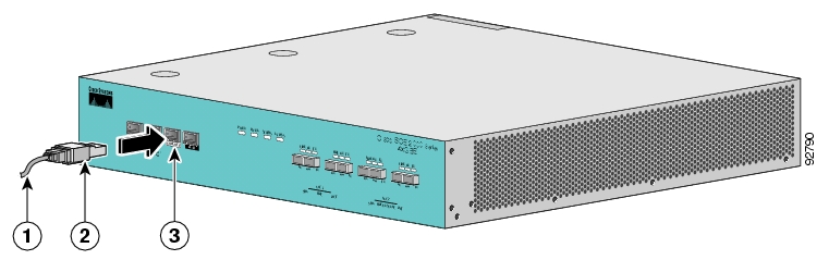
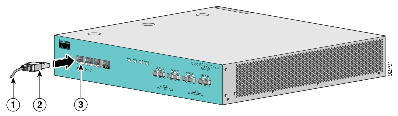
How to Cable the Management Port
The SCE 2000 has two management ports, labeled Mng1 and Mng 2.
SUMMARY STEPS
1.
2.
DETAILED STEPS
Step 1
Figure 5-2 Cabling the Management Port
Step 2
•
•
Make sure that you push on the RJ-45 connector attached to the cable until you hear a click, which indicates that the connector is fully inserted and secured in the receptacle. Gently pull on the plug to confirm whether the plug is locked into the socket.
If the Link LED on the SCE 2000 management port does not light, try removing the cable and reinserting it firmly into the module socket. To disconnect the plug from the socket, press down on the raised portion on top of the plug, releasing the latch. You should hear an audible click indicating the latch has released. Carefully pull the plug out of the socket.
If the management port Link LED on the SCE 2000 still does not light, verify that the cable is connected correctly to the appropriate network element on its second end.
How to Verify Management Interface Connectivity
If the SCE 2000 platform has been powered up, test now to verify that connectivity has been established between the SCE 2000 and the remote management host. If the SCE 2000 platform is not powered up, perform this step after starting the SCE 2000 platform.
SUMMARY STEPS
1.
2.
DETAILED STEPS
Step 1
There are two Mng LEDs — Link/Active, and 10/100/1000 (refer to Front Panel).
At this point, check that the Link/Active LED is green.
The state of the 10/100/1000 LED will depend on the Ethernet network settings.
Green indicates 100 Mbps and `Off' indicates 10 Mbps.
Step 2
Note
This verifies that an active connection exists between the specified station and the management port.
The ping program sends an echo request packet to an IP address and then awaits a reply. Ping output can help you evaluate path-to-host reliability, delays over the path, and whether the host can be reached or is functioning.
EXAMPLE:
The following example displays a typical ping response where the target IP address is 10.1.1.201.
C:\>ping 10.1.1.201
pinging 10.1.1.201 ...
PING 10.1.1.201: 56 data bytes
64 bytes from host (10.1.1.201): icmp_seq=0. time=0. ms
64 bytes from host (10.1.1.201): icmp_seq=1. time=0. ms
64 bytes from host (10.1.1.201): icmp_seq=2. time=0. ms
64 bytes from host (10.1.1.201): icmp_seq=3. time=0. ms
----10.1.1.201 PING Statistics----
4 packets transmitted, 4 packets received, 0% packet loss
round-trip (ms) min/avg/max = 0/0/0
![]()
![]()
![]()
![]()
![]()
![]()
![]()
![]()
Posted: Fri Aug 24 07:15:38 PDT 2007
All contents are Copyright © 1992--2007 Cisco Systems, Inc. All rights reserved.
Important Notices and Privacy Statement.