|
|

Table Of Contents
Information About Topology Considerations
Information About Link Continuity
Information About Asymmetric Routing Topology
Information About Physical Topologies
Information About Two Cascaded SCE 2000s For Dual Links
Information About Topology-Related Parameters
Information About Topology
This chapter describes the possible deployment topologies of the SCE 2000 .
The Cisco SCE solution offers a number of basic topology options that permit the user to tailor the SCE Platform to fit the needs of a particular installation. An understanding of the various issues and options is crucial to designing, deploying, and configuring the topology that best meets the requirements of the individual system.
•
Information About Topology Considerations
The SCE 2000 Platform
The SCE 2000 introduces a solution for dual links with load sharing and asymmetrical routing and support for fail-over between two SCE platforms.
The SCE 2000 supports wire speed processing of full-duplex 2-Gigabit Ethernet streams. The SCE 2000 can, therefore, be deployed in a multi-link environment, either in a single or dual SCE platform topology.
•
•
Information About Topology Considerations
There are several issues that must be considered in order to arrive at the optimum configuration of the topology-related parameters:
•
•
•
•
These issues determine three important aspects of system deployment and configuration:
•
•
•
Functionality
The SCE 2000 can serve one of two general functions:
•
In order to perform control functions, the SCE 2000 must be physically installed as an inline installation and the connection mode must be "inline".
•
Either an inline installation or an optical splitter installation may be used for monitoring only. In the latter case connection mode must be "receive-only".
Number of links
The SCE 2000 can be deployed in a single GBE link or in two GBE links. The two-link topology may implement load-sharing and the SCE 2000 in this case is able to process both directions of a bi-directional flow even if they split to both links.
Redundancy
When a high degree of reliability is desired, a second SCE 2000 Platform should be installed to provide backup operation capabilities. The combination of two SCE 2000 s guarantees uninterrupted functioning in case of a failure of one of the platforms. The two SCE 2000 s are cascaded, so that, although all processing is performed only in the active SCE 2000 , the standby SCE 2000 is constantly updated with all the necessary information so that it can instantly take over processing the traffic on the data links should the active SCE 2000 fail.
If only preservation of the network links is required, and uninterrupted functionality of the SCE 2000 is not required, a single SCE 2000 is sufficient.
Information About Link Continuity
The bypass mechanism of the SCE 2000 allows traffic to continue to flow, if desired, even if the device itself is not functioning.
Note that when the SCE 2000 is connected to the network through an optical splitter, a failure of the SCE 2000 does not affect the traffic flow, as the traffic continues to flow through the optical splitter.
•
Bypass Mechanism
The SCE 2000 includes a Network Interface Card with a bypass mechanism that is enabled upon SCE 2000 failure. In addition, when connected in-line it can also be enabled in normal operation to simultaneously bypass traffic flow to the other side and direct it internally for analysis. In this case it maintains "receive-only"-like monitoring functions, when control functionality is not required.
The bypass card supports the following four modes:
•
•
•
•
Maintaining the Network Links vs Maintaining SCE 2000 Platform Functionality
When a single SCE 2000 is deployed, the user may decide that in case of a failure, maintaining the network link is more important than providing the SCE 2000 functionality. In this scenario, when the SCE 2000 detects a failure that requires a reboot process for recovering, it immediately switches to Bypass mode, allowing all traffic to bypass the SCE 2000 . The SCE 2000 stays in Bypass mode maintaining the network link, albeit without SCE 2000 processing, until the SCE 2000 fully recovers from the failure and is ready to resume normal functioning.
Alternatively, the user may decide that the SCE 2000 functionality is sufficiently crucial to require severing the link if the SCE 2000 platform fails. In this case, when the SCE 2000 detects a failure that requires a reboot process for recovering, it immediately switches to Cutoff mode, stopping all traffic flow. The SCE 2000 stays in Cutoff mode, halting all traffic, until it fully recovers from the failure and is ready to resume normal functioning. In Cutoff the physical interface is blocked, enabling the network device connected to the SCE 2000 to sense that the link is down.
Information About Asymmetric Routing Topology
•
Asymmetric Routing Topology
In some Service Control deployments, asymmetrical routing occurs between potential service control insertion points. Asymmetrical routing can cause a situation in which the two directions of a bi-directional flow pass through different SCE platforms, resulting in each SCE platform seeing only one direction of the flow (either the inbound traffic or the outbound traffic).
This problem is typically solved by connecting the two SCE platforms in cascade mode (or through an MGSCP cluster), thereby making sure that both directions of a flow run through the same SCE platform. However, this is sometimes not feasible, due to the fact that the SCE platforms sharing the split flow are geographically remote (especially common upon peering insertion). In this type of scenario, the asymmetric routing solution enables the SCE platform to handle such traffic, allowing SCA BB to classify traffic based on a single direction and to apply basic reporting and global control features to uni-directional traffic.
Asymmetric Routing and Other Service Control Capabilities
Asymmetric routing can be combined with most other Service Control capabilities, however there are some exceptions.
Service Control capabilities that cannot be used in an asymmetric routing topology include the following:
•
•
•
•
–
–
–
–
–
Information About Physical Topologies
Following are descriptions of a number of physical topologies that the SCE 2000 supports.
•
•
•
Information About Inline SCE 2000 Topologies
A single SCE 2000 supports both single GBE link and dual GBE link topologies.
•
•
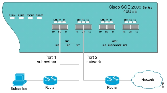
Single Link: Inline Topology
Typically, the SCE 2000 is connected in a full duplex GBE link between two devices (Router, BRAS, etc.). When the SCE 2000 is installed as an inline installation, it physically resides on the data link between the subscribers and the network.
Figure 3-1 Single SCE Platform Single Link: In-line Topology
When configuring the SCE 2000 , an inline installation is referred to as "inline" connection mode.
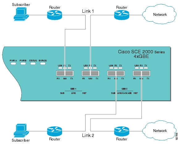
Dual link: Inline Installation
In this topology, one SCE 2000 is connected inline in two full duplex, GBE links.
In case the two links are load-shared, asymmetrical routing might occur, and some of the flows may be split, i.e. the upstream packets of the flow go on one link, and the downstream packets go on the other link.
When installed in this topology, the SCE 2000 completely overcomes this phenomenon, and provides its normal functionality as if asymmetrical routing were not occurring in the two links.
Figure 3-2 Single SCE Platform Dual Link Inline Topology
This topology supports both monitoring and control functionality, and is referred to as "inline" connection mode.
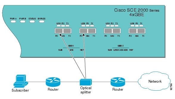
Single Link: Receive-only Topology
In this topology, an optical splitter resides physically on the GBE link between the subscribers and the network. The traffic passes through the optical splitter, which splits traffic to the SCE 2000 . The SCE 2000, therefore, only receives traffic and does not transmit.
Figure 3-3 Single SCE Platform Single Link: Receive-Only Topology
When configuring the SCE 2000, an optical splitter topology is referred to as "receive-only" connection mode.
Note that in an optical splitter topology, the SCE 2000 only enables traffic monitoring functionality.
Note
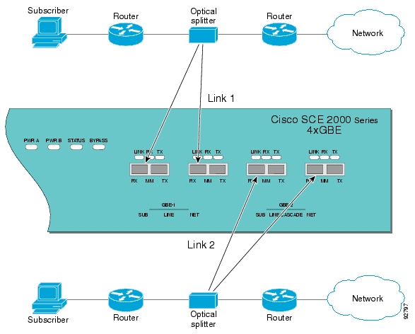
Dual Link: Receive-Only Topology
In this topology, one SCE 2000 is connected in receive-only mode to two full duplex, GBE links using optical splitters. If the two links are load-shared, asymmetrical routing might occur, and some of the flows may be split, i.e. the upstream packets of the flow go on one link, and the downstream packets go on the other link.
When installed in this topology, the SCE 2000 completely overcomes this phenomenon, and provides its normal monitoring functionality as if asymmetrical routing were not occurring in the two links.
This installation supports monitoring functionality only, and is configured as "receive-only" connection mode.
Figure 3-4 SCE Platform Dual Link Receive-Only Topology
Note
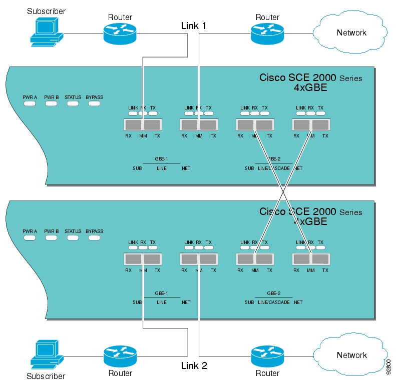
Information About Two Cascaded SCE 2000s For Dual Links
In this topology, two cascaded SCE 2000 s are used. This allows a fail-over solution, where in case of a failure of one SCE 2000 the functionality that the SCE 2000 provides is preserved by the redundant platform.
•
Two Cascaded SCE 2000s: Inline Topology
This topology allows both control and monitoring functionality where redundancy is required and "inline" connection is used. The two SCE 2000 s are cascaded, so the primary SCE 2000 processes the traffic of the two links, while the secondary SCE 2000 only bypasses the traffic of its links to the primary SCE 2000 for processing, and then bypasses the processed traffic back to the link. The two SCE 2000 s also exchange keep-alive messages and subscriber state information.
In case the primary SCE 2000 fails, the two SCE 2000 s switch their roles, and this way fail-over is provided.
Figure 3-5 Two SCE Platforms: Dual Link Inline Topology
This fail-over solution preserves the SCE 2000 functionality and the network link:
•
•
•
Information About Topology-Related Parameters
Refer to the following sections to determine the correct values for all topology-related parameters before beginning run the initial setup of the SCE 2000 .
•
•
SCE 2000 Configuration
There are four topology-related parameters:
•
–
–
–
–
•
It is applicable only in a cascade topology.
•
It is applicable only in a cascade topology.
•
Any of these parameters may be configured via either the setupcommand or the connection-modecommand.
Connection Mode Parameter
The connection mode parameter refers directly to the physical topology in which the SCE 2000 is installed. The connection mode depends on two factors:
•
–
–
•
The connection mode parameter is determined by the physical deployment of the SCE 2000 , as follows:
•
•
•
•
Physically Connected Links Parameter
If the system consists of more than one device, this parameter defines which link is connected to this SCE 2000 . Currently the system supports a maximum of two links, which are designated link 0 and link 1.
Priority
In a cascade topology, the user must define the priority of each SCE 2000 .
•
•
Note that these defaults apply only when both devices are started together. However, if the primary SCE 2000 fails and then recovers, it will not revert to active status, but remains in standby status, while the secondary device remains active.
On-Failure Mode Parameter
As described in the section The Bypass Mechanism, the bypass card supports four different modes. The following two modes are possible when the SCE 2000 is not operational due to platform failure or boot:
•
•
The Forwarding mode enables control of traffic flow and is not compatible with the non-operational status.
In a single SCE 2000 topology, the value of this parameter is determined by whether or not the link can be completely cut when the SCE 2000 fails, or whether traffic flow should continue across the link in spite of platform failure.
•
–
–
•
–
![]()
![]()
![]()
![]()
![]()
![]()
![]()
![]()
Posted: Fri Aug 24 07:14:01 PDT 2007
All contents are Copyright © 1992--2007 Cisco Systems, Inc. All rights reserved.
Important Notices and Privacy Statement.