|
|

Table Of Contents
Configuring ATM Router Module Interfaces
Overview of the ATM Router Module
Hardware and Software Restrictions
Configuring ATM Router Module Interfaces
Default ATM Router Module Interface Configuration Without Autoconfiguration
Manual ATM Router Module Interface Configuration
Configuring LECs on ATM Router Module Interfaces (Catalyst 8540 MSR)
Confirming the LEC Configuration
RFC 1483 Configuration Example
Configuring Classical IP over ATM in a PVC Environment
Configuring Packet Flooding on a PVC
Displaying the Bridging Configuration
Configuring ATM Router Module Interfaces
This chapter describes steps required to configure the ATM router module on the Catalyst 8540 MSR, Catalyst 8510 MSR, and LightStream 1010 ATM switch routers. The ATM router module allows you to integrate Layer 3 switching with ATM switching on the same ATM switch router.
Note
This chapter provides advanced configuration instructions for the Catalyst 8540 MSR, Catalyst 8510 MSR, and LightStream 1010 ATM switch routers. For complete descriptions of the commands mentioned in this chapter, refer to the ATM Switch Router Command Reference publication. For hardware installation and cabling instructions, refer to the ATM Port Adapter and Interface Module Installation Guide.
Note
This chapter includes the following sections:
•
•
•
•
•
Overview of the ATM Router Module
The ATM router module interface module allows you to integrate Layer 3 routing and ATM switching within a single chassis. When you install the ATM router module, you no longer need to choose either Layer 3 or ATM technology, as is frequently the case with enterprise campus and MAN applications.
The Catalyst 8540 MSR ATM router module offers the following benefits:
•
•
•
•
•
•
•
•
•
The Catalyst 8510 MSR and LightStream 1010 ATM router module offers the following benefits:
•
•
•
•
•
•
•
•
The ATM router module has no external interfaces. All traffic is sent and received through internal interfaces to the switching fabric. The Catalyst 8540 MSR ATM router module has two internal ports and for the Catalyst 8510 MSR and LightStream 1010 ATM router module has one internal port.
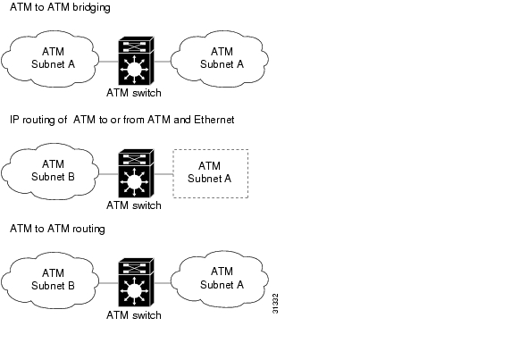
The ATM router module can perform one or more of the functions described in Figure 21-1.
Figure 21-1 ATM Router Module Routing and Bridging Functions
The ATM router module receives Address Resolution Protocol (ARP) messages and route broadcasts from connected ATM peers and sends the appropriate control information to the route processor. On the ATM side, the ATM router module connects to the switching fabric as would any other interface module.
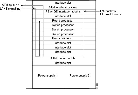
On the Catalyst 8540 MSR, the ATM router module supports LANE clients (LECs), but not the LANE servers (LES, LECS, and BUS). It separates the control and data path so that all LANE control messages are handled by the route processor, and data messages are switched on the ATM router module port, as shown in Figure 21-2. The LEC is configured on the ATM router module interface, but control message traffic is sent to the route processor by the ATM router module. The ATM router module sends all ATM data traffic to the appropriate VCs.
Figure 21-2 ATM Router Module Traffic Flow (Catalyst 8540 MSR)
Hardware and Software Restrictions
The following hardware restrictions apply to the Catalyst 8540 MSR, Catalyst 8510 MSR, and LightStream 1010 ATM router modules:
•
•
•
•
Note
The following software restrictions apply to the Catalyst 8540 MSR, Catalyst 8510 MSR, and LightStream 1010 ATM router modules:
•
•
•
•
•
The Catalyst 8540 MSR, Catalyst 8510 MSR, and LightStream 1010 ATM router modules do not support the following features:
•
•
•
•
•
•
•
•
•
•
•
•
•
•
The following software restrictions apply to the Catalyst 8540 MSR ATM router modules:
•
•
•
The following software restrictions apply to Catalyst 8510 MSR and LightStream 1010 ATM router modules:
•
•
•
Note
Note
Configuring ATM Router Module Interfaces
The you can configure the following features directly on the ATM router module interfaces:
•
•
•
•
•
•
Note
Note
Note
Default ATM Router Module Interface Configuration Without Autoconfiguration
If ILMI is disabled or if the connecting end node does not support ILMI, the following defaults are assigned to all ATM router module interfaces:
•
•
•
•
•
Manual ATM Router Module Interface Configuration
To manually change the default configuration values, perform the following steps, beginning in global configuration mode:
Example
The following example shows how to change the default number of active VCI bits:
Switch(config)# interface atm 0/0/0Switch(config-if)# atm maxvci-bits 10Configuring LECs on ATM Router Module Interfaces (Catalyst 8540 MSR)
The procedures for configuring LANE clients (LECs) on the ATM router module are the same as the configuration for LECs on the route processor, with one exception. To specify an ATM router module interface, rather than the route processor interface, use the interface atm card/subcard/port command. On the route processor, you would use the interface atm 0 command.
Note
Note
To configure a LEC on an ATM router module interface, use the following commands, beginning in global configuration mode:
Example
The following example shows how to configure two LECs on an ATM router module interface:
Switch# configure terminalSwitch(config)# interface atm 1/0/0.4 multipointSwitch(config-subif)# ip address 40.0.0.1 255.0.0.0Switch(config-subif)# lane client ethernet VLAN4Switch(config-subif)# exitSwitch(config)# interface atm 1/0/0.5 multipointSwitch(config-subif)# ip address 50.0.0.1 255.0.0.0Switch(config-subif)# lane client ethernet VLAN5Switch(config-subif)# exitSwitch(config)# router ospf 1Switch(config-router)# network 40.0.0.0 0.255.255.255 area 0Switch(config-router)# network 50.0.0.0 0.255.255.255 area 0For more information on configuring LECs on ATM router module interfaces, see the "Configuring a LAN Emulation Client on the ATM Switch Router" section . For a detailed description of LANE and its components, refer to Cisco IOS Switching Services Configuration Guide: Virtual LANs.
LEC Configuration Examples
The examples in this section show how to configure LANE clients (LECs) on networks with two routers and one Catalyst 8540 MSR. For detailed information on configuring the LANE server (LES), LANE configuration server (LECS), and broadcast-and-unknown server (BUS), refer to "Configuring LAN Emulation"
Caution
LANE Routing Over ATM
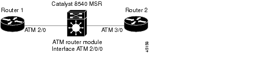
The following example shows how to configure LANE routing over ATM with the ATM router module. Figure 21-3 shows an example of a network for LANE routing over ATM.
Figure 21-3 Example Network for LANE Routing Over ATM
Router 1 ATM Interface
Router1# configure terminalRouter1(config)# interface atm 2/0Router1(config-if)# ip address 1.0.0.1 255.0.0.0Router1(config-if)# atm pvc 1 0 5 qsaalRouter1(config-if)# atm pvc 2 0 16 ilmiRouter1(config-if)# lane client ethernet happyRouter1(config-if)# endRouter1#ATM Switch Router ATM Router Module Interface
Switch# configure terminalSwitch(config)# interface atm 2/0/0Switch(config-if)# ip address 1.0.0.2 255.0.0.0Switch(config-if)# lane client ethernet BACKBONESwitch(config-if)# endSwitch#Router 2 ATM Interface
Router2# configure terminalRouter2(config)# interface atm 3/0Router2(config-if)# ip address 1.0.0.3 255.0.0.0Router2(config-if)# no ip mroute-cacheRouter2(config-if)# atm pvc 1 0 5 qsaalRouter2(config-if)# atm pvc 2 0 16 ilmiRouter2(config-if)# no atm ilmi-keepaliveRouter2(config-if)# lane client ethernet BACKBONERouter2(config-if)# endRouter2#For detailed information on configuring LANE clients (LECs), refer to "Configuring LAN Emulation"
LANE Routing from ATM to Ethernet
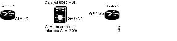
The following example shows how to configure LANE routing from ATM to Ethernet with the ATM router module. Figure 21-4 shows an example of a LANE network for LANE routing from ATM to Ethernet.
Figure 21-4 Example Network for LANE Routing from ATM to Ethernet
Router 1 ATM Interface
Router1# configure terminalRouter1(config)# interface atm 2/0Router1(config-if)# ip address 1.0.0.1 255.0.0.0Router1(config-if)# atm pvc 1 0 5 qsaalRouter1(config-if)# atm pvc 2 0 16 ilmiRouter1(config-if)# lane client ethernet happyRouter1(config-if)# endRouter1#ATM Switch Router ATM Router Module Interface
Switch# configure terminalSwitch(config)# interface atm 2/0/0Switch(config-if)# ip address 1.0.0.2 255.0.0.0Switch(config-if)# lane client ethernet BACKBONESwitch(config-if)# endSwitch#ATM Switch Router Ethernet Interface
Switch# configure terminalSwitch(config)# interface gigabitethernet 9/0/0Switch(config-if)# ip address 129.1.0.1 255.255.255.0Switch(config-if)# no ip directed-broadcastSwitch(config-if)# endSwitch#Router 2 Ethernet Interface
Router2# configure terminalRouter2(config)# interface gigabitethernet 9/0/0Router2(config-if)# ip address 129.1.0.2 255.255.255.0Router2(config-if)# no ip directed-broadcastRouter2(config-if)# endRouter2#Configure the desired network routing protocol, such as RIP, OSPF, or EIGRP, on Ethernet interfaces. For more information on configuring networking protocols and routing, refer to the Layer 3 Switching Software Feature and Configuration Guide.
LANE Bridging Between ATM and Ethernet
The following example show how to configure LANE bridging between ATM and Ethernet with the ATM router module. Figure 21-5 shows an example of a network for LANE bridging between ATM and Ethernet.
Figure 21-5 Example Network for LANE Bridging Between ATM and Ethernet
Router 1 ATM Interface
Router1# configure terminalRouter1(config)# interface atm 2/0Router1(config-if)# atm pvc 1 0 5 qsaalRouter1(config-if)# atm pvc 2 0 16 ilmiRouter1(config-if)# lane client ethernet happyRouter1(config-if)# bridge-group 1Router1(config-if)# endRouter1#Router 1 Bridge Interface
Router1# configure terminalRouter1(config)# interface BVI1Router1(config-if)# ip address 130.2.3.1 255.255.255.0Router1(config-if)# exitRouter1(config)# bridge 1 protocol ieeeRouter1(config)# bridge 1 route ipRouter1(config)# bridge irbRouter1(config)# endRouter1#ATM Switch Router ATM Router Module Interface
Switch# configure terminalSwitch(config)# interface atm 2/0/0Switch(config-if)# lane client ethernet BACKBONESwitch(config-if)# bridge-group 1Switch(config-if)# exitSwitch(config)# bridge 1 protocol ieeeSwitch(config)# endSwitch#ATM Switch Router Ethernet Interface
Switch# configure terminalSwitch(config)# interface gigabitethernet9/0/0Switch(config-if)# bridge-group 1Switch(config-if)# endSwitch#Router 2 Ethernet Interface
Router2# configure terminalRouter2(config)# interface ethernet 9/0/0Router2(config-if)# bridge-group 1Router2(config-if)# endRouter2#Router 2 Bridge Interface
Router2# configure terminalRouter2(config)# interface BVI1Router2(config-if)# ip address 130.2.3.4 255.255.255.0Router2(config-if)# exitRouter2(config)# bridge 1 protocol ieeeRouter2(config)# bridge 1 route ipRouter2(config)# bridge irbRouter2(config)# endRouter2#For more information on configuring bridging, refer to the Layer 3 Switching Software Feature and Configuration Guide.
Confirming the LEC Configuration
To confirm the LEC configuration on the ATM switch router, use the following EXEC commands:
Configuring RFC 1483
This section describes how to configure multiprotocol encapsulation over ATM, as defined in RFC 1483, on the ATM router module.
The primary use of RFC 1483 is to carry multiple Layer 3 and bridged frames over ATM. RFC 1483 traffic is routed through an ATM router module interface using static map lists. Static map lists provide an alternative to using the ATM Address Resolution Protocol (ARP) and ATM Inverse ARP (InARP) mechanisms. For more information on static map lists, refer to the "Mapping a Protocol Address to a PVC Using Static Map Lists" section.
For a detailed description of RFC 1483, refer to the Guide to ATM Technology.
Note
To configure multiprotocol encapsulation over ATM on the ATM router module interface, use the following commands, beginning in global configuration mode:
Example
The following example shows how to configure RFC 1483 on an ATM router module interface, beginning in global configuration mode:
Switch(config)# interface atm 1/0/0.1011 multipointSwitch(config-subif)# ip address 10.1.1.1 255.255.255.0Switch(config-subif)# map-group net1011Switch(config-subif)# atm pvc 2 1011 interface atm 3/0/0 0 1011 encap aal5snapSwitch(config-subif)# exitSwitch(config)# map-list net1011Switch(config-map-list)# ip 10.1.1.2 atm-vc 1011Switch(config-map-list)# endSwitch#RFC 1483 Configuration Example
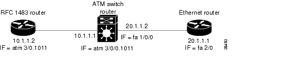
The following example shows how to configure for RFC 1483 with two routers and one ATM switch router.
The ATM switch router has an ATM router module in slot 0, a Fast Ethernet interface module in slot 1, and an ATM interface module in slot 3. One router has an ATM interface processor in slot 3. The other router has a Fast Ethernet interface module in slot 2.
Figure 21-6 shows an example of an RFC 1483 network.
Figure 21-6 Example Network for RFC 1483
Router with ATM Interface
RouterA# configure terminalRouterA(config)# interface atm 3/0.1011 multipointRouterA(config-subif)# ip address 10.1.1.2 255.255.255.0RouterA(config-subif)# atm pvc 1011 0 1011 aal5snapRouterA(config-subif)# map group net1011RouterA(config-subif)# ipx network 1011RouterA(config-subif)# exitRouterA(config)# map-list net1011RouterA(config-map-list)# ip 10.1.1.1 atm-vc 1011RouterA(config-map-list)# ipx 1011.1111.1111.1111 atm-vc 1011RouterA(config-map-list)# exitRouterA(config)#ATM Switch Router
Switch# configure terminalSwitch(config)# interface atm 0/0/0.1011 multipointSwitch(config-subif)# ip address 10.1.1.1 255.255.255.0Switch(config-subif)# ipx network 1011Switch(config-subif)# map-group net1011Switch(config-subif)# atm pvc 2 1011 interface atm 3/0/0 0 1011Switch(config-subif)# map-list net1011Switch(config-map-list)# ip 10.1.1.2 atm-vc 1011Switch(config-map-list)# ipx 1011.2222.2222.2222 atm-vc 1011Switch(config-map-list)# exitSwitch(config)# interface fastethernet 1/0/0Switch(config-if)# ip address 20.1.1.2 255.255.255.0Switch(config-if)# ipx network 2011Switch(config-if)# endSwitch#
Note
Ethernet Router
RouterB# configure terminalRouterB(config)# ipx routingRouterB(config)# interface fastethernet 2/0RouterB(config-if)# ip address 20.1.1.1 255.255.255.0RouterB(config-if)# ipx network 2011RouterB(config-if)# endRouterB#Configuring Classical IP over ATM in a PVC Environment
This section describes how you configure classical IP over ATM, as described by RFC 1577, in a PVC environment on the ATM router module. The ATM Inverse ARP (InARP) mechanism is applicable to networks that use permanent virtual channels (PVCs), where connections are established but the network addresses of the remote ends are not known. For more information on configuring ATM ARP and ATM InARP, refer to the "Configuring Classical IP over ATM" section .
For a description of classical IP over ATM and RFC 1577, refer to the Guide to ATM Technology.
In a PVC environment, configure the ATM InARP mechanism on the ATM router module by performing the following steps, beginning in global configuration mode:
Repeat these tasks for each PVC you want to create.
The inarp minutes interval specifies how often inverse ARP datagrams are sent on this virtual circuit. The default value is 15 minutes.
Example
The following example shows how to configure an IP-over-ATM interface on interface ATM 3/0/0, using a PVC with AAL5SNAP encapsulation, InARP set to ten minutes, VPI = 2, and VCI = 100:
Switch(config)# interface atm 3/0/0Switch(config-if)# ip address 11.11.11.11 255.255.255.0Switch(config-if)# atm pvc 2 100 interface atm 0/0/0 50 100 encap aal5snap inarp 10Configuring Bridging
All PVCs configured on ATM router module interfaces are used for bridging.
To configure bridging on an ATM router module interface, use the following commands, beginning in global configuration mode:
Example
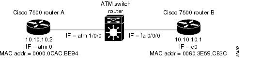
The following example shows how to configure bridging on a Catalyst 8540 MSR with a Fast Ethernet interface module in slot 0, an ATM interface module in slot 1, and an ATM router module in slot 3.
Figure 21-7 shows an example bridging network.
Figure 21-7 Example Network for Bridging
Switch(config)# interface atm 3/0/0Switch(config-if)# atm pvc 2 200 interface atm 1/0/0 0 200Switch(config-if)# bridge-group 5Switch(config-if)# endSwitch(config)# interface fastethernet 0/0/0Switch(config-if)# no cdp enableSwitch(config-if)# bridge-group 5Switch(config-if)# endSwitch(config)# bridge 5 protocol ieeeConfiguring Packet Flooding on a PVC
Typically, a specific static map list configuration is not required for bridging to occur. In case of packet flooding, the bridging mechanism individually sends the packet to be flooded on all PVCs configured on the interface. To restrict the broadcast of the packets to only a subset of the configured PVCs you must define a separate static map list. Use the broadcast keyword in the static-map command to restrict packet broadcasting.
Example
In the following example only PVC 2, 200 is used for packet flooding:
Switch(config)# interface atm 3/0/0Switch(config-if)# no ip addressSwitch(config-if)# no ip directed-broadcastSwitch(config-if)# map-group bg_1Switch(config-if)# atm pvc 2 200 interface atm 1/0/1 0 200Switch(config-if)# atm pvc 2 201 interface atm 1/0/1 0 300Switch(config-if)# bridge-group 5Switch(config-if)# endSwitch(config)# map-list bg_1Switch(config-map-list)# bridge atm-vc 200 broadcast
Note
Displaying the Bridging Configuration
To display the bridging configuration on the ATM router module interface, use the following privileged EXEC command:
Example
Switch# show bridge verboseTotal of 300 station blocks, 297 freeCodes: P - permanent, S - selfBG Hash Address Action Interface VC Age RX count TX count5 28/0 0000.0ce4.341c forward Fa0/0/0 -5 2A/0 0000.0cac.be94 forward ATM3/0/0 2005 FA/0 0060.3e59.c63c forward Fa0/0/0 -Configuring IP Multicast
To configure IP multicast over an RFC 1483 permanent virtual channel (PVC) on an ATM router module, use the following commands, beginning in global configuration mode:
Example
Switch(config)# ip multicast-routingSwitch(config)# interface atm 1/0/0.1011 multipointSwitch(config-subif)# ip address 10.1.1.1 255.255.255.0Switch(config-subif)# map-group net1011Switch(config-subif)# atm pvc 2 1011 interface atm 3/0/0 0 1011 encap aal5snapSwitch(config-subif)# ip pim dense-modeSwitch(config-subif)# exitSwitch(config)# map-list net1011Switch(config-map-list)# ip 10.1.1.2 atm-vc 1011 broadcast
Note
![]()
![]()
![]()
![]()
![]()
![]()
![]()
![]()
Posted: Mon Oct 11 09:13:43 PDT 2004
All contents are Copyright © 1992--2004 Cisco Systems, Inc. All rights reserved.
Important Notices and Privacy Statement.