|
|

Table Of Contents
Configuring IMA Port Adapter Interfaces
Configuring the T1/E1 IMA Port Adapter
Default T1/E1 IMA Interface Configuration
Configuring the T1/E1 IMA Interface
Configuring IMA Group Functions
Creating an IMA Group Interface
Adding an Interface to an Existing IMA Group
Deleting an Interface from an IMA Group
Configuring IMA Group Parameters
Configuring IMA Group Minimum Active Links
Configuring IMA Group Interface Clock Mode
Configuring IMA Group Link Differential Delay
Configuring IMA Group Frame Length
Configuring IMA Group Test Pattern
Configuring IMA Port Adapter Interfaces
This chapter describes inverse multiplexing over ATM (IMA) and the steps required to configure the IMA port adapters in the Catalyst 8540 MSR, Catalyst 8510 MSR, and LightStream 1010 ATM switch routers. These port adapters group multiple low-speed links into one larger virtual trunk or IMA group.
Note
This chapter provides advanced configuration instructions for the Catalyst 8540 MSR, Catalyst 8510 MSR and LightStream 1010 ATM switch routers. For complete descriptions of the commands mentioned in this chapter, refer to the ATM Switch Router Command Reference publication. For hardware installation and cabling instructions, refer to the ATM Port Adapter and Interface Module Installation Guide.
For more information on how to configure your IMA-specific network equipment, refer to the Cisco IOS publications on the Documentation CD-ROM.
This chapter includes the following sections:
•
•
•
Note
Overview of IMA
IMA allows you to aggregate multiple low-speed links into one larger virtual trunk or IMA group. An inverse multiplexer appears to your ATM switch router as one logical pipe. This IMA group provides modular bandwidth for user access to ATM networks for connections between ATM network elements at rates between the traditional order multiplex levels, such as between T1 or E1 and T3 or E3.
IMA involves inverse multiplexing and demultiplexing of ATM cells in a cyclical fashion among links grouped to form a higher bandwidth logical group with a rate approximately the sum of the link rates. This group of links is called an IMA group.
Inverse multiplexing in the transmit direction controls the distribution of cells onto the group of physical links available to the IMA group interface. It also handles differential delays and deals with links that are added or dropped, or fail and are later restored. In the receive direction, the IMA interface performs differential delay compensation and recombines the cells into the original ATM cell stream while allowing minimal cell delay variation (CDV). The IMA process of splitting and recombining the ATM cell stream is as transparent to the layer above as a traditional single-link physical layer interface.
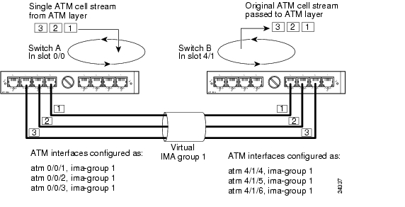
Figure 20-1 illustrates the configuration of the T1 IMA port adapters (with eight ports each) on two switches which create a virtual IMA group connection.
Figure 20-1 IMA Grouping Example
IMA groups terminate at each end of the IMA virtual link. The transmit IMA receives the ATM cell stream from the ATM layer and distributes it on a cell-by-cell basis across the multiple T1 or E1 links within the IMA group. At the far-end, the receiving IMA recombines the cells from each link, also on a cell-by-cell basis, recreating the original ATM cell stream. The aggregate cell stream is then passed to the ATM layer.
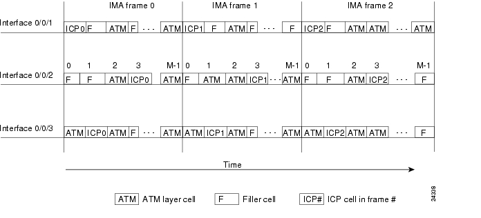
The IMA frame is the unit of control in the IMA protocol. An IMA frame is a series of consecutive cells. Periodically, the transmit IMA sends special cells that permit reconstruction of the ATM cell stream at the receiving IMA. These cells, defined as IMA Control Protocol (ICP) cells, provide the definition of an IMA frame. The transmitter must align the transmission of IMA frames on all links (shown in Figure 20-2) to allow the receiver to adjust for differential link delays among the constituent physical links. Based on this required behavior, the receiver can detect the differential delays by measuring the arrival times of the IMA frames on each link.
The transmitting end sends cells continuously. If no ATM layer cells are sent between ICP cells within an IMA frame, the transmit IMA sends filler cells to maintain a continuous stream of cells at the physical layer. Filler cells, which provide cell rate decoupling at the IMA sublayer, are discarded by the receiving IMA.
A new OAM cell is defined for use by the IMA protocol. This cell has codes that define it as either an ICP cell or a filler cell.
Within the IMA frame, the ICP cell appears at the ICP cell offset position, which can vary among the links. Figure 20-2 shows an example of the transmission of IMA frames over three links. On interface 0/0/1, the ICP cells have their cell offset set to 0 and are the first cells in each IMA frame. On interface 0/0/2, the ICP cells have the ICP cell offset set to 3 and are the fourth cells in each IMA frame. On interface 0/0/3, the ICP cells have their ICP cell offset set to 1 and are the second cells in each IMA frame.
Figure 20-2 IMA Frames
Note
Configuring the T1/E1 IMA Port Adapter
The T1/E1 IMA port adapter provides eight physical ports. Each port adapter supports up to four IMA groups and independent ATM interfaces. The following are possible combinations:
–
–
–
–
–
The T1 line operates at 1.544 Mbps, which is equivalent to 24 time slots (DS0 channels). The T1 time slot provides usable bandwidth of n x 64 kbps, where n is the time slot from 1 to 24. The E1 line operates at 2.048 Mbps.
T1/E1 IMA port adapters support interface overbooking. For configuration information, see the "Configuring Interface Overbooking" section on page 8-37.
Note
Default T1/E1 IMA Interface Configuration
The following defaults are assigned to all T1/E1 IMA port adapter interfaces:
•
•
•
•
The following port adapter types have specific defaults assigned.
T1 port adapter:
•
•
•
•
•
E1 port adapter:
•
•
•
•
The following defaults are assigned to all IMA groups:
•
•
•
•
•
•
Configuring the T1/E1 IMA Interface
To manually change any of your default configuration values, perform the following steps, beginning in global configuration mode:
Note
Example
The following example shows how to change the clock source to free running:
Switch(config)# interface atm 0/0/3Switch(config-if)# clock source free-runningDisplaying the T1/E1 IMA Interface Configuration
To display the physical T1/E1 IMA interface configuration, use the following EXEC command:
show controllers atm card/subcard/port
Displays the physical interface configuration and status.
Example
The following example shows a T1 IMA ATM interface 0/0/3 configuration, including the change to the clock source configuration from the previous section:
Switch# show controller atm 0/0/3ATM0/0/3 is upPAM State is UPFirmware Version: 1.6FPGA Version : 1.2Boot version : 1.2Port type: T1 Port rate: 1.5 Mbps Port medium: UTPPort status:Good Signal Loopback:None Flags:8000fdl is DISABLEDYellow alarm enabled in both tx and rxlinecode is B8ZSTX Led: Traffic Pattern RX Led: Traffic Pattern CD Led: GreenTX clock source: free-running
T1 Framing Mode: ESF ADM formatLBO (Cablelength) is short 133Counters:Key: txcell - # cells transmittedrxcell - # cells receivedhcs - # uncorrectable HEC errorschece - # rx Correctable HEC errorsuicell - # unassigned/idle cells droppedoocd - # rx out of cell deliniationrx_fovr - # rx FIFO over runtx_fovr - # tx FIFO over runcoca - # tx Change of cell allignmentpcv - # path code violationslcv - # line code violationses - #--More--Configuring IMA Group Functions
To configure IMA group functions on an ATM switch router, perform the tasks in the following sections:
•
•
•
Creating an IMA Group Interface
To create an IMA group interface, first link a physical interface to the IMA group. After configuring the physical interface as part of an IMA group, you can then create the IMA group interface. An IMA group interface is identified by its card, subcard, and IMA group number. For example, IMA group 1 configured on the physical interface card 0 and subcard 0 is identified as 0/0/ima1. IMA group numbers range from 0 to 3.
Note
To create an IMA group interface at both ends of the connection, perform the following steps, beginning in global configuration mode:
Note
Example
The following example shows how to create the IMA group interface 0/0/ima1 shown in Figure 20-1 starting with Switch A, ATM interface 0/0/1:
SwitchA(config)# interface atm 0/0/1SwitchA(config-if)# shutdownSwitchA(config-if)# ima-group 1SwitchA(config-if)# no shutdownSwitchA(config-if)# exitSwitchA(config)# interface atm 0/0/ima1SwitchA(config-if)# no shutdownThe following example shows how to create the IMA group interface 4/1/ima1 shown in Figure 20-1 on Switch B, ATM interface 4/1/4:
SwitchB(config)# interface atm 4/1/4SwitchB(config-if)# shutdownSwitchB(config-if)# ima-group 1SwitchB(config-if)# no shutdownSwitchB(config-if)# exitSwitchB(config)# interface atm 4/1/ima1SwitchB(config-if)# no shutdownAdding an Interface to an Existing IMA Group
An interface can be added to an existing IMA group link by assigning the IMA group number.
Note
To configure the interfaces at both ends of the connection as members of an existing IMA group, perform the following steps, beginning in global configuration mode:
Note
Examples
The following example shows how to configure ATM interface 0/0/2 on Switch A as part of the IMA group 1 shown in Figure 20-1:
SwitchA(config)# interface atm 0/0/2SwitchA(config-if)# shutdownSwitchA(config-if)# ima-group 1SwitchA(config-if)# no shutdownThe following example shows how to configure ATM interface 4/1/5 on Switch B as part of the IMA group 1 shown in Figure 20-1:
SwitchB(config)# interface atm 4/1/5SwitchB(config-if)# shutdownSwitchB(config-if)# ima-group 1SwitchB(config-if)# no shutdownThe following example shows how to move ATM interface 4/1/5 on Switch B to the IMA group 3:
SwitchB(config)# interface atm 4/1/5SwitchA(config-if)# shutdownSwitchB(config-if)# ima-group 3SwitchB(config-if)# no shutdownDisplaying the IMA Group Configuration
To display the IMA group configuration, use the following EXEC commands:
Example
The following example shows the IMA group interface configuration for IMA group 0/0/ima1 interface:
SwitchA# show ima interface atm 0/0/ima1ATM0/0/ima1 is upGroup Index = 2State: NearEnd = operational, FarEnd = operationalFailureStatus = noFailureIMA Group Current Configuration:MinNumTxLinks = 1 MinNumRxLinks = 1DiffDelayMax = 25 FrameLength = 128NeTxClkMode = common(ctc) CTC_Reference_Link = ATM0/0/3TestLink = 3 Testpattern = Not SpecifiedTestProcStatus = disabled GTSM change timestamp = 990426154350IMA Link Information:Link Physical Status NearEnd Rx Status Test Status----- --------------- ----------------- ---------------ATM0/0/2 up active disabledATM0/0/3 up active disabledThe following example shows the interface configuration for T1 IMA group 0/0/ima1:
SwitchA# show interfaces atm 0/0/ima1ATM0/0/ima1 is up, line protocol is upHardware is imapam_t1_imaMTU 4470 bytes, sub MTU 4470, BW 1500 Kbit, DLY 0 usec, rely 255/255, load 1/255Encapsulation ATM, loopback not set, keepalive not supportedLast input 00:00:00, output 00:00:00, output hang neverLast clearing of "show interface" counters neverInput queue: 0/75/0 (size/max/drops); Total output drops: 0Queueing strategy: weighted fairOutput queue: 0/1000/64/0 (size/max total/threshold/drops)Conversations 0/0/256 (active/max active/max total)Reserved Conversations 0/0 (allocated/max allocated)5 minute input rate 0 bits/sec, 0 packets/sec5 minute output rate 0 bits/sec, 0 packets/sec223 packets input, 11819 bytes, 0 no bufferReceived 0 broadcasts, 0 runts, 0 giants, 0 throttles0 input errors, 0 CRC, 0 frame, 0 overrun, 0 ignored, 0 abort215 packets output, 11395 bytes, 0 underruns0 output errors, 0 collisions, 1 interface resets0 output buffer failures, 0 output buffers swapped outThe following example shows the ATM layer interface configuration of the T1 IMA group 0/0/ima1:
SwitchA# show atm interface atm 0/0/ima1Interface: ATM0/0/ima1 Port-type: imapam_t1_imaIF Status: UP Admin Status: upAuto-config: enabled AutoCfgState: completedIF-Side: Network IF-type: NNIUni-type: not applicable Uni-version: not applicableMax-VPI-bits: 8 Max-VCI-bits: 14Max-VP: 255 Max-VC: 16383ConfMaxSvpcVpi: 255 CurrMaxSvpcVpi: 255ConfMaxSvccVpi: 255 CurrMaxSvccVpi: 255ConfMinSvccVci: 35 CurrMinSvccVci: 35Svc Upc Intent: pass Signalling: EnabledATM Address for Soft VC: 47.0091.8100.0000.0040.0b0a.2a81.4000.0c80.0090.00Configured virtual links:PVCLs SoftVCLs SVCLs TVCLs PVPLs SoftVPLs SVPLs Total-Cfgd Inst-Conns3 0 0 0 0 0 0 3 3Logical ports(VP-tunnels): 0Input cells: 105 Output cells: 1095 minute input rate: 0 bits/sec, 0 cells/sec5 minute output rate: 0 bits/sec, 0 cells/secInput AAL5 pkts: 58, Output AAL5 pkts: 60, AAL5 crc errors: 0Deleting an Interface from an IMA Group
To delete an interface from an IMA group, perform the following steps, beginning in global configuration mode:
Example
The following example shows how to delete an interface from an IMA group:
Switch(config)# interface atm 0/0/1Switch(config-if)# no ima-groupConfirming the Interface Deletion
To confirm the interface deletion from the IMA group, use the following EXEC command:
show ima interface atm card/subcard/port
Displays IMA group interface configuration and status.
Example:
The following example shows how to verify that the interface is deleted from the IMA group:
SwitchA# show ima interface atm 0/0/1ATM0/0/1 is not a part of IMA groupDeleting an IMA Group
To delete an IMA group, use the following global configuration command:
no interface atm card/subcard/imagroup
Deletes the IMA group from the T1/E1 IMA interface.
Note
Example
The following example shows how to delete ATM interface 0/0/ima1 and administratively shut down the member interfaces:
Switch(config)#no interface atm 0/0/ima1Confirming the IMA Group Deletion
To confirm the IMA group deletion, perform the following steps in user EXEC mode:
show ima interface [atm card/subcard/imagroup [detailed]]
Displays IMA group interface configuration and status.
Example
The following example shows how to verify that the interface is deleted from the IMA group:
Switch# configure terminalEnter configuration commands, one per line. End with CNTL/Z.Switch(config)# interface atm 0/0/2Switch(config-if)# shutSwitch(config-if)# ima-group 0Switch(config-if)# no shutSwitch(config-if)# exitSwitch(config)# interface atm 0/0/ima0Switch(config-if)# no shutSwitch(config-if)# endSwitch# show ima interface atm 0/0/ima0ATM0/0/ima0 is upGroup Index = 5State: NearEnd = operational, FarEnd = operationalFailureStatus = noFailureIMA Group Current Configuration:MinNumTxLinks = 1 MinNumRxLinks = 1DiffDelayMax = 25 FrameLength = 128NeTxClkMode = common(ctc) CTC_Reference_Link = ATM0/0/2TestLink = 2 Testpattern = Not SpecifiedTestProcStatus = disabled GTSM change timestamp = 000210165420IMA Link Information:Link Physical Status NearEnd Rx Status Test Status----- --------------- ----------------- ---------------ATM0/0/2 up active disabledSwitch# configure terminalEnter configuration commands, one per line. End with CNTL/Z.Switch(config)# interface atm 0/0/ima0Switch(config-if)# endSwitch(config)# no interface atm 0/0/ima0Switch(config)# exitSwitch# show ima interface atm 0/0/ima0^% Invalid input detected at '^' marker.Switch#Configuring IMA Group Parameters
This section describes how to configure inverse multiplexing over ATM (IMA) group parameters after configuring an IMA group at the interface level. These tasks include configuring active minimum links, interface clock mode, link differential delay, frame length, and test pattern.
Configuring IMA Group Minimum Active Links
You can configure an IMA group to require a minimum number of active links. This number is the minimum number of links required for the IMA group to become operational and provides a guaranteed minimum bandwidth. For example, if the active-minimum-links command number is configured as 3, the minimum number of active links necessary for the IMA group to be active is three and the minimum bandwidth available is approximately 3 x T1 speed.
To configure the minimum active links on the IMA group, perform the following steps, beginning in global configuration mode:
Note
Example
The following example shows how to configure the minimum number of active links that must be up for the IMA group to function as 3:
SwitchA(config)# interface atm 0/0/ima1SwitchA(config-if)# ima active-links-minimum 3Displaying the IMA Group Minimum Active Links Configuration
To display the IMA group minimum active links configuration, use the following EXEC command:
show ima interface [atm card/subcard/imagroup [detailed]]
Displays IMA group interface configuration and status.
Example
The following example shows the IMA group interface minimum active links configuration:
SwitchA# show ima interfaceATM0/0/ima1 is upGroup Index = 5State: NearEnd = operational, FarEnd = operationalFailureStatus = noFailureIMA Group Current Configuration:DiffDelayMax = 25 FrameLength = 128NeTxClkMode = common(ctc) CTC_Reference_Link = ATM0/0/2TestLink = 2 Testpattern = Not SpecifiedTestProcStatus = disabled GTSM change timestamp = 990427165502IMA Link Information:Link Physical Status NearEnd Rx Status Test Status----- --------------- ----------------- ---------------ATM0/0/2 up active disabledATM0/0/3 up active disabledATM0/0/4 up active disabledATM0/0/5 up active disabledConfiguring IMA Group Interface Clock Mode
The links configured as part of a IMA group interface can derive their clocking from one single clock source using common transmit clocking (CTC) mode, or the link clocking can be derived individually from different clock sources using independent transmit clocking (ITC) mode. For example, if three interfaces are configured as members of an IMA group interface, one can be configured to use the reference clock, and the remaining links can derive their clocking from the local oscillator.
To configure the clocking mode on the IMA group, perform the following steps, beginning in global configuration mode:
Example
The following example shows how to configure the IMA group clocking mode as independent:
SwitchA(config)# interface atm 0/0/ima1SwitchA(config-if)# ima clock-mode independentDisplaying the IMA Group Interface Clock Mode Configuration
To display the IMA group transmit clock mode configuration, use the following EXEC command:
show ima interface [atm card/subcard/imagroup [detailed]]
Displays IMA group interface configuration and status.
Example
The following example shows the IMA group clock mode configuration:
SwitchA# show ima interfaceATM0/0/ima1 is upGroup Index = 4State: NearEnd = operational, FarEnd = operationalFailureStatus = noFailureIMA Group Current Configuration:MinNumTxLinks = 1 MinNumRxLinks = 1DiffDelayMax = 25 FrameLength = 128TestLink = 3 Testpattern = Not SpecifiedTestProcStatus = disabled GTSM change timestamp = 990427121150IMA Link Information:Link Physical Status NearEnd Rx Status Test Status----- --------------- ----------------- ---------------ATM0/0/2 up active disabledATM0/0/3 up active disabledConfiguring IMA Group Link Differential Delay
The transmitter on the T1/E1 IMA port adapter must align the transmission of IMA frames on all links as shown in Figure 20-2. Alignment allows the receiver to adjust for differential delays among the members of the IMA group. Based on this required behavior, the receiver can detect the differential delays by measuring the arrival times of the IMA frames on each link.
The transmitting end of the IMA group connection sends cells continuously. If there are no ATM layer cells to send between ICP cells within an IMA frame, the transmit IMA sends filler cells to maintain a continuous stream of cells at the physical layer.
The receiving end of the IMA group connection must allocate sufficient buffer space to compensate for the differential delay between the member links. The maximum differential delay value configured for the IMA group determines the size of these buffers.
To configure the maximum differential delay allowed in the IMA group, perform the following steps, beginning in global configuration mode:
Example
The following example shows how to configure the maximum allowable differential delay to 100 milliseconds between all interfaces assigned to the IMA group.
SwitchA(config)# interface atm 0/0/ima1SwitchA(config-if)# ima differential-delay-maximum 100Displaying the IMA Group Link Differential Delay Configuration
To display the IMA group maximum differential delay configuration, use the following EXEC command:
show ima interface [atm card/subcard/imagroup [detailed]]
Displays IMA group interface configuration and status.
Example
The following example shows the IMA group maximum differential delay configuration:
SwitchA# show ima interfaceATM0/0/ima1 is upGroup Index = 4State: NearEnd = operational, FarEnd = operationalFailureStatus = noFailureIMA Group Current Configuration:MinNumTxLinks = 1 MinNumRxLinks = 1NeTxClkMode = common(ctc) CTC_Reference_Link = ATM0/0/3TestLink = 3 Testpattern = Not SpecifiedTestProcStatus = disabled GTSM change timestamp = 990427135611IMA Link Information:Link Physical Status NearEnd Rx Status Test Status----- --------------- ----------------- ---------------ATM0/0/2 up active disabledATM0/0/3 up active disabledConfiguring IMA Group Frame Length
The IMA protocol uses the frame length parameter to determine the number of cells that make up an IMA frame.The IMA group frame length determines the amount of framing overhead and the amount of data lost in case of frame corruption or loss. A small frame length causes more overhead but loses less data if a problem occurs. The recommended frame length is 128.
To configure the frame length on the IMA group, perform the following steps, beginning in global configuration mode:
Example
The following example shows how to configure the frame length transmitted as 256 cells for IMA group 0/0/ima1:
SwitchA(config)# interface atm 0/0/ima1SwitchA(config-if)# ima frame-length 256Displaying the IMA Group Frame Length Configuration
To display the IMA group frame length configuration, use the following EXEC command:
show ima interface [atm card/subcard/imagroup [detailed]]
Displays IMA group interface configuration and status.
Example
The following example shows the IMA group frame length configuration:
SwitchA# show ima interfaceATM0/0/ima1 is upGroup Index = 4State: NearEnd = operational, FarEnd = operationalFailureStatus = noFailureIMA Group Current Configuration:MinNumTxLinks = 1 MinNumRxLinks = 1NeTxClkMode = common(ctc) CTC_Reference_Link = ATM0/0/3TestLink = 3 Testpattern = Not SpecifiedTestProcStatus = disabled GTSM change timestamp = 990427143739IMA Link Information:Link Physical Status NearEnd Rx Status Test Status----- --------------- ----------------- ---------------ATM0/0/2 up active disabledATM0/0/3 up active disabledConfiguring IMA Group Test Pattern
An IMA group can have a test pattern defined to provide extra support to verify the connectivity of links within an IMA group. It uses a test pattern sent over one link to verify connectivity to the rest of the group. The test pattern should be looped over all the other links in the group at the far end of the connection. The test procedure is performed using the ICP cells exchanged between both ends of the IMA virtual links.
To configure the test pattern to be transmitted on the IMA group, perform the following steps, beginning in global configuration mode:
Examples
The following example shows how to configure the test pattern 8 to transmit over link 3 of IMA group 0/0/ima1:
SwitchA(config)# interface atm 0/0/ima1SwitchA(config-if)# ima test link 3 pattern 8The following example shows how to stop the test on IMA group 0/0/ima1:
SwitchA(config)# interface atm 0/0/ima1SwitchA(config-if)# no ima testDisplaying the IMA Group Test Pattern Configuration
To display the IMA group test pattern configuration, use the following EXEC command:
show ima interface [atm card/subcard/imagroup [detailed]]
Displays IMA group interface configuration and status.
Example
The following example shows the IMA group test pattern configuration:
SwitchA# show ima interfaceATM0/0/ima1 is upGroup Index = 4State: NearEnd = operational, FarEnd = operationalFailureStatus = noFailureIMA Group Current Configuration:MinNumTxLinks = 1 MinNumRxLinks = 1DiffDelayMax = 25 FrameLength = 128NeTxClkMode = common(ctc) CTC_Reference_Link = ATM0/0/3TestProcStatus = operating GTSM change timestamp = 990427143950IMA Link Information:Link Physical Status NearEnd Rx Status Test Status----- --------------- ----------------- ---------------ATM0/0/2 up active operatingATM0/0/3 up active operating
![]()
![]()
![]()
![]()
![]()
![]()
![]()
![]()
Posted: Mon Oct 11 09:19:40 PDT 2004
All contents are Copyright © 1992--2004 Cisco Systems, Inc. All rights reserved.
Important Notices and Privacy Statement.