|
|

Table Of Contents
LANE Functionality and Requirements
LANE Router and Switch Router Requirements
Creating a LANE Plan and Worksheet
Displaying LANE Default Addresses
Entering the ATM Address of the Configuration Server
Setting Up the Configuration Server Database
Enabling the Configuration Server
Configuring a LAN Emulation Client on the ATM Switch Router
Configuring Fault-Tolerant Operation
Monitoring and Maintaining the LANE Components
Default Configuration for a Single Emulated LAN
Default Configuration for a Single Emulated LAN with Backup LECS and LES on the ATM Switch Router
Default Configuration for a Token Ring ELAN with IP Source Routing (Catalyst 8510 MSR and LightStream 1010)
Configuring LAN Emulation
This chapter describes LAN emulation (LANE) and how to configure it on the ATM switch router.
Note
This chapter provides advanced configuration instructions for the Catalyst 8540 MSR, Catalyst 8510 MSR, and LightStream 1010 ATM switch routers. For an overview of LANE architecture and operation, refer to the Guide to ATM Technology. For complete descriptions of the commands mentioned in this chapter, refer to the ATM Switch Router Command Reference publication. For a detailed description of LANE and its components, refer to Cisco IOS Switching Services Configuration Guide: Virtual LANs.
This chapter contains the following sections:
•
LANE Functionality and Requirements
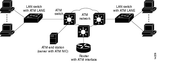
LANE uses ATM as a backbone to interconnect existing legacy LANs. In doing so, LANE allows legacy LAN users to take advantage of ATM's benefits without requiring modifications to end station hardware or software.
Multiple emulated LANs (ELANs), which are logically separated, can share the same physical ATM network and the same physical ATM interface. LANE makes an ATM interface look like one or more separate Ethernet or Token Ring interfaces.
LANE services provide connectivity between ATM-attached devices and LAN-attached devices. Two primary applications for the LANE protocol are as follows:
•
•
Figure 13-1 illustrates the various connections LANE provides.
Figure 13-1 LANE Concept
Refer to the Guide to ATM Technology for the following background topics on LANE:
•
•
•
•
•
LANE Router and Switch Router Requirements
You must manually configure Q.2931 over Signaling ATM Adaptation Layer (QSAAL) and ILMI signaling PVCs on routers and edge LAN switch routers to run LANE. However, these signaling permanent virtual channels (PVCs) are automatically configured on the ATM switch router.
Note
At least one ATM switch router is required to run LANE. For example, you cannot run LANE on routers connected back-to-back.
LANE Configuration Tasks
Before you begin to configure LANE, you must decide whether you want to set up one or multiple emulated LANs. If you set up multiple emulated LANs, you must also decide where the servers and clients will be located, and whether to restrict the clients that can belong to each emulated LAN. The procedure for configuring bridged emulated LANs is the same as for any other LAN.
To configure LANE, complete the tasks in the following sections:
•
•
•
•
Note
•
An ATM cloud can contain multiple configuration servers.
Every ELAN must have at least a LAN emulation server/broadcast-and unknown server (LES/BUS) pair, the maximum is 10. Every LANE cloud (one or multiple ELANs) must have at least one LAN emulation configuration server (LECS).
You can configure some emulated LANs with unrestricted membership and some emulated LANs with restricted membership. You can also configure a default emulated LAN, which must have unrestricted membership.
After LANE is configured, you can monitor and maintain the components, as described in the "Monitoring and Maintaining the LANE Components" section .
Creating a LANE Plan and Worksheet
Draw up a plan and a worksheet for your LANE scenario, containing the following information and leaving spaces for the ATM address of each LANE component on each subinterface of each participating router or switch router:
•
•
•
•
•
•
•
The last three items in this list are very important; they determine how you set up each emulated LAN in the configuration server database.
Automatic ATM Addressing and Address Templates for LANE Components
The ATM switch router automatically assigns ATM addresses to LANE components using the scheme described in the Guide to ATM Technology. You can also override the automatic address assignments using an ATM address template.
You can use ATM address templates in many LANE commands that assign ATM addresses to LANE components or that link client ATM addresses to emulated LANs. Using templates can greatly simplify the use of these commands.
Note
LANE ATM address templates can use two types of wildcards: an asterisk (*) to match any single character, and an ellipsis (...) to match any number of leading or trailing characters.
In LANE, a prefix template explicitly matches the prefix but uses wildcards for the end station interface (ESI) and selector fields. An ESI template explicitly matches the ESI field but uses wildcards for the prefix and selector fields. Table 13-1 shows how the values of unspecified digits are determined when an ATM address template is used.
Table 13-1 Values of Unspecified Digits in ATM Address Templates
Prefix (first 13 bytes)
Obtained from ATM switch router via Integrated Local Management Interface (ILMI)
ESI (next 6 bytes)
Filled with the slot MAC address1 plus
•
•
•
•
Selector field (last 1 byte)
Subinterface number, in the range 0 through 255
1 The lowest MAC addresses in the pool addresses assigned to the ATM interface plus a value that indicates the LANE component.
Rules for Assigning Components to Interfaces and Subinterfaces
The following rules apply to assigning LANE components to the major ATM interface and its subinterfaces:
•
The assignment of any other component to the major interface is identical to assigning that component to the 0 subinterface.
•
•
•
Note
Example LANE Plan and Worksheet
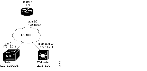
This section is an example of the LANE plan and worksheet that would be created for the example network configuration described in the "Default Configuration for a Single Emulated LAN" section .
Note
Figure 13-2 shows the single emulated LAN example network.
Figure 13-2 LANE Plan Example Network
The following information describes the LANE plan in Figure 13-2:
•
—Location: ATM_Switch
—Interface: atm 0
—ATM address: 47.00918100000000E04FACB401.00E04FACB405.00•
—Location: Switch_1
—Interface/Subinterface: atm 0.1
—Type: Ethernet
—ATM address: 47.00918100000000E04FACB401.00E04FACB403.01•
—Location: Switch_1
—Interface/Subinterface: atm 0.1
—Type: Ethernet
—ATM address: "use default"•
—Location: ATM_Switch
—Name: eng_dbase
—ELAN name: eng_elan
—Default ELAN name: eng_elan
—ATM address: 47.00918100000000E04FACB401.00E04FACB403.01•
—Location: ATM_Switch
—Interface/Subinterface: atm 0.1
—Server/BUS name: eng_elan
—IP Address/Subnet mask: 172.16.0.4 255.255.0.0
—Type: Ethernet•
—Location: Switch_1
—Interface/Subinterface: atm 0.1
—Server/BUS name: eng_elan
—Type: Ethernet•
—Location: Router_1
—Interface/Subinterface: atm 3/0.1
—Server/BUS name: eng_elan
—IP Address/Subnet mask: 172.16.0.1 255.255.0.0
—Type: Ethernet
Note
Continue with the following sections to start configuring LANE on your ATM network.
Displaying LANE Default Addresses
To make configuration easier, you should display the LANE default addresses for each router or switch router that is running any of the LESs or services and write down the displayed addresses on your worksheet.
To display the default LANE addresses, use the following EXEC command:
show lane default-atm-addresses
Displays the LANE default addresses for all ATM interfaces present on the router or switch router.
Example
The following example displays the default LANE addresses:
Switch# show lane default-atm-addressesinterface ATM13/0/0:LANE Client: 47.00918100000000E04FACB401.00E04FACB402.**LANE Server: 47.00918100000000E04FACB401.00E04FACB403.**LANE Bus: 47.00918100000000E04FACB401.00E04FACB404.**LANE Config Server: 47.00918100000000E04FACB401.00E04FACB405.00note: ** is the subinterface number byte in hexEntering the ATM Address of the Configuration Server
You must enter the configuration server ATM address into the ATM switch routers and save it permanently, so that the value is not lost when the device is reset or powered off. The configuration server address can be specified for all of the ATM switch routers, or per port.
To enter the configuration server addresses for all of the ATM switch routers, perform the following steps in global configuration mode:
For examples of these commands, see the "LANE Configuration Examples" section .
Setting Up the Configuration Server Database
After you have determined all LESs, BUSs, and LECS on all ATM subinterfaces on all routers and switch routers that will participate in LANE, and have displayed their ATM addresses, you can use the information to populate the configuration server's database.
You can set up a default emulated LAN, whether or not you set up any other emulated LANs. You can also set up some emulated LANs with restricted membership and others with unrestricted membership.
To set up the LANE database, complete the tasks in the following subsections as appropriate for your emulated LAN plan and scenario. To set up fault-tolerant operation, see the "Configuring Fault-Tolerant Operation" section .
Setting Up the Database for the Default Emulated LAN Only
When you configure a router as the LECS for one default emulated LAN, you provide the following information:
•
•
•
•
When you set up a database of only a default unrestricted emulated LAN, you do not have to specify where the LANE clients are located. That is, when you set up the configuration servers database for a single default emulated LAN, you do not have to provide any database entries that link the ATM addresses of any clients with the emulated LAN name.
To set up the LECS for the default emulated LAN, perform the following steps, beginning in global configuration mode:
In Step 2, enter the ATM address of the server for the specified emulated LAN, as noted in your worksheet and obtained in the "Displaying LANE Default Addresses" section . You can have any number of servers per emulated LAN for fault tolerance. Entry order determines priority: the first entry has the highest priority unless you override it with the index option.
If you are setting up only a default emulated LAN, the elan-name value in Step 2 is the same as the default emulated LAN name you provide in Step 4.
To set up fault-tolerant operation, see the "Configuring Fault-Tolerant Operation" section .
For examples of these commands, see the "LANE Configuration Examples" section .
Setting Up the Database for Unrestricted-Membership Emulated LANs
When you set up a database for unrestricted emulated LANs, you create database entries that link the name of each emulated LAN to the ATM address of its server.
However, you can choose not to specify the locations of the LANE clients. That is, when you set up the configuration server database, you do not have to provide any database entries that link the ATM addresses or media access control (MAC) addresses of any clients with the emulated LAN name.
To configure a router or switch router as the LECS for multiple emulated LANs with unrestricted membership, perform the following steps, beginning in global configuration mode:
In Steps 2 and 4, enter the ATM address of the server for the specified emulated LAN, as noted in your worksheet and obtained in the "Displaying LANE Default Addresses" section .
To set up fault-tolerant operation, see the "Configuring Fault-Tolerant Operation" section .
For examples of these commands, see the "LANE Configuration Examples" section .
Setting Up the Database for Restricted-Membership Emulated LANs
When you set up the database for restricted-membership emulated LANs, you create database entries that link the name of each emulated LAN to the ATM address of its server. However, you also must specify where the LANE clients are located. That is, for each restricted-membership emulated LAN, you provide a database entry that explicitly links the ATM address or MAC address of each client of that emulated LAN with the name of that emulated LAN.
When clients for the same restricted-membership emulated LAN are located in multiple routers, each client's ATM address or MAC address must be linked explicitly with the name of the emulated LAN. As a result, you must configure as many client entries (See Step 7 in the following procedure) as you have clients for emulated LANs in all the routers. Each client will have a different ATM address in the database entries.
To set up the configuration server for emulated LANs with restricted membership, perform the following steps, beginning in global configuration mode:
To set up fault-tolerant operation, see the "Configuring Fault-Tolerant Operation" section .
Enabling the Configuration Server
After you create the database entries appropriate to the type and to the membership conditions of the emulated LANs, you enable the configuration server on the selected ATM interface, router, or switch router, and specify that the configuration server's ATM address is to be computed automatically.
To enable the configuration server, perform the following steps, beginning in global configuration mode:
For examples of these commands, see the "LANE Configuration Examples" section .
Note
Setting Up LESs and Clients
For each device that participates in LANE, set up the necessary servers and clients for each emulated LAN; then display and record the server and client ATM addresses. Be sure to keep track of the router or switch router interface where the LECS will be located.
For one default emulated LAN, you must set up one set of servers: one as a primary server and the rest as backup servers for the same emulated LAN. For multiple emulated LANs, you can set up servers for another emulated LAN on a different subinterface or on the same interface of this router or switch router, or you can place the servers on a different router.
When you set up a server and BUS on a router, you can combine them with a client on the same subinterface, a client on a different subinterface, or no client at all on the router.
Where you put the clients is important, because any router with clients for multiple emulated LANs can route frames between those emulated LANs.
Note
Setting Up the Server, BUS, and a Client on a Subinterface
To set up the server, BUS, and (optionally) clients for an emulated LAN, perform the following steps, beginning in global configuration mode:
If the emulated LAN in Step 2 will have restricted membership, consider carefully whether you want to specify its name here. You will specify the name in the LECS's database when it is set up. However, if you link the client to an emulated LAN, and by some mistake it does not match the database entry linking the client to an emulated LAN, this client will not be allowed to join this or any other emulated LAN.
If you do decide to include the name of the emulated LAN linked to the client in Step 3 and later want to associate that client with a different emulated LAN, make the change in the configuration server's database before you make the change for the client on this subinterface.
Each emulated LAN is a separate subnetwork. In Step 4, make sure that the clients of the same emulated LAN are assigned protocol addresses on the same subnetwork, and that clients of different emulated LANs are assigned protocol addresses on different subnetworks.
For examples of these commands, see the "LANE Configuration Examples" section .
Setting Up a Client on a Subinterface
On any given router or switch router, you can set up one client for one emulated LAN or multiple clients for multiple emulated LANs without a server and BUS. You can set up a client for a given emulated LAN on any routers you select to participate in that emulated LAN. Any router with clients for multiple emulated LANs can route packets among those emulated LANs.
To set up a client for an emulated LAN, perform the following steps, beginning in global configuration mode:
Note
Each emulated LAN is a separate subnetwork. In Step 2, make sure that the clients of the same emulated LAN are assigned protocol addresses on the same subnetwork, and that clients of different emulated LANs are assigned protocol addresses on different subnetworks.
Note
Example (Catalyst 8540 MSR)
The following example shows how to configure a client for emulated LAN on an ATM router module subinterface:
Switch(config)# interface atm 10/0/1.1Switch(config-if)# ip address 172.16.4.0 255.255.0.0Switch(config-if)# lane client ethernet elan_1205For additional examples of these commands, see the "LANE Configuration Examples" section .
Configuring a LAN Emulation Client on the ATM Switch Router
This section explains how to configure a LANE client connection from the ATM switch router in the headquarters building to the route processor interface (or optional ATM router module interface on the Catalyst 8540 MSR) of the ATM switch router.
Note
A route processor (or optional ATM router module interface) configured as a LANE client allows you to configure the ATM switch router from a remote host.
Configuring an Ethernet LANE Client
To configure the route processor interface (or optional ATM router module interface on the Catalyst 8540 MSR) as an Ethernet LANE client on the ATM switch router, perform the following steps, beginning in global configuration mode:
Note
Example
The following example shows how to specify the LANE configuration server (LECS) address and configure a LANE client on the route processor interface to emulate an Ethernet connection using the automatic ATM address assignment:
Switch(config)# atm lecs-address 47.0091.0000.0000.0000.0000.0000.0000.00Switch(config)# interface atm 0Switch(config-if)# lane client ethernet eng_elanFor additional examples of these commands, see the "LANE Configuration Examples" section . For LANE client configuration examples on ATM router module interfaces, refer to "Configuring LECs on ATM Router Module Interfaces (Catalyst 8540 MSR)" section .
Configuring Fault-Tolerant Operation
The LANE simple server redundancy feature creates fault tolerance using standard LANE protocols and mechanisms. If a failure occurs on the LECS or on the LES/BUS, the emulated LAN can continue to operate using the services of a backup LES. This protocol is called the Simple Server Redundancy Protocol (SSRP).
For a detailed description of SSRP for LANE, refer to the Guide to ATM Technology.
Enabling Redundant LECSs and LES/BUSs
To enable fault tolerance, you enable multiple, redundant, and standby LECSs and multiple, redundant, and standby LES/BUSs. This allows the connected LANE components to obtain the global list of LECS addresses. Our LANE continues to operate seamlessly with other vendors' LANE components, but fault tolerance is not effective when other vendors' LANE components are present.
To configure multiple LES/BUSs for emulated LANs on the routers or switch routers, perform the following steps, beginning in global configuration mode:
Server redundancy guards against the failure of the hardware on which LES components are running. This includes all the ATM interface cards in our routers and Catalyst switches. Fault tolerance is not effective for ATM network or switch router failures.
Caution
Load the configuration table data using the configure network command. This method minimizes errors and enables the database to be maintained centrally in one place.
For examples of these commands, see the "LANE Configuration Examples" section .
Implementation Considerations
For important considerations when implementing SSRP, refer to the LANE discussion in the Guide to ATM Technology.
Caution
Monitoring and Maintaining the LANE Components
After configuring LANE components on an interface or any of its subinterfaces, on a specified subinterface, or on an emulated LAN, you can display their status. To show LANE information, use the following EXEC commands:
LANE Configuration Examples
The examples in the following sections illustrate how to configure LANE for the following cases:
•
•
•
All examples use the automatic ATM address assignment method described in the "Automatic ATM Addressing and Address Templates for LANE Components" section .
These examples show the LANE configurations, not the process of determining the ATM addresses and entering them.
Note
Default Configuration for a Single Emulated LAN
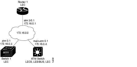
The following examples show how to configure one Cisco 7505 router, one ATM switch, and one Catalyst 5500 switch for a single emulated LAN. Configurations for both Ethernet and Token Ring emulated LANs are shown.
The ATM switch contains the LECS, LES, BUS, and an LEC. The router and Catalyst 5500 switch each contain an LEC for the emulated LAN. This example uses all LANE default settings. For example, it does not explicitly set ATM addresses for the different LANE components that are colocated on the ATM switch. Membership in this emulated LAN is not restricted (see Figure 13-3).
Figure 13-3 Single Emulated LAN Example Network
Ethernet Example
ATM Switch
ATM_Switch# show lane default-atm-addressesinterface ATM13/0/0:LANE Client: 47.00918100000000E04FACB401.00E04FACB402.**LANE Server: 47.00918100000000E04FACB401.00E04FACB403.**LANE Bus: 47.00918100000000E04FACB401.00E04FACB404.**LANE Config Server: 47.00918100000000E04FACB401.00E04FACB405.00note: ** is the subinterface number byte in hexATM_Switch# configure terminalEnter configuration commands, one per line. End with CNTL/Z.ATM_Switch(config)# atm lecs-address-default 47.00918100000000E04FACB401.00E04FACB405.00ATM_Switch(config)# endATM_Switch#ATM_Switch# copy system:running-config nvram:startup-configBuilding configuration...[OK]ATM_Switch# configure terminalEnter configuration commands, one per line. End with CNTL/Z.ATM_Switch(config)# lane database eng_dbaseATM_Switch(lane-config-database)# name eng_elan server-atm-address 47.00918100000000E04FACB401.00E04FACB403.01ATM_Switch(lane-config-database)# default-name eng_elanATM_Switch(lane-config-database)# endATM_Switch# show lane databaseLANE Config Server database table 'eng_dbase'default elan: eng_elanelan 'eng_elan': un-restrictedserver 47.00918100000000E04FACB401.00E04FACB403.01 (prio 0)ATM_Switch# configure terminalEnter configuration commands, one per line. End with CNTL/Z.ATM_Switch(config)# interface atm 0ATM_Switch(config-if)# lane config database eng_dbaseATM_Switch(config-if)# lane config auto-config-atm-addressATM_Switch(config-if)# exitATM_Switch(config)# endATM_Switch# show lane configLE Config Server ATM13/0/0 config table: eng_dbaseAdmin: up State: operationalLECS Mastership State: active masterlist of global LECS addresses (42 seconds to update):47.00918100000000E04FACB401.00E04FACB405.00 <-------- meATM Address of this LECS: 47.00918100000000E04FACB401.00E04FACB405.00 (auto)cumulative total number of unrecognized packets received so far: 0cumulative total number of config requests received so far: 0cumulative total number of config failures so far: 0ATM_Switch# configure terminalEnter configuration commands, one per line. End with CNTL/Z.ATM_Switch(config)# interface atm 0.1ATM_Switch(config-subif)# lane server-bus ethernet eng_elanATM_Switch(config-subif)# ip address 172.16.0.4 255.255.0.0ATM_Switch(config-subif)# endATM_Switch# show laneLE Config Server ATM13/0/0 config table: eng_dbaseAdmin: up State: operationalLECS Mastership State: active masterlist of global LECS addresses (46 seconds to update):47.00918100000000E04FACB401.00E04FACB405.00 <-------- meATM Address of this LECS: 47.00918100000000E04FACB401.00E04FACB405.00 (auto)vcd rxCnt txCnt callingParty82 0 0 47.00918100000000E04FACB401.00E04FACB403.01 LES eng_elan 0 activecumulative total number of unrecognized packets received so far: 0cumulative total number of config requests received so far: 0cumulative total number of config failures so far: 0LE Server ATM13/0/0.1 ELAN name: eng_elan Admin: up State: operationaltype: ethernet Max Frame Size: 1516ATM address: 47.00918100000000E04FACB401.00E04FACB403.01LECS used: 47.00918100000000E04FACB401.00E04FACB405.00 connected, vcd 81LE BUS ATM13/0/0.1 ELAN name: eng_elan Admin: up State: operationaltype: ethernet Max Frame Size: 1516ATM address: 47.00918100000000E04FACB401.00E04FACB404.01ATM_Switch# configure terminalEnter configuration commands, one per line. End with CNTL/Z.ATM_Switch(config)# interface atm 0.1ATM_Switch(config-subif)# lane client ethernet eng_elanATM_Switch(config-subif)# endATM_Switch# show lane clientLE Client ATM13/0/0.1 ELAN name: eng_elan Admin: up State: operationalClient ID: 1 LEC up for 30 secondsELAN ID: 0Join Attempt: 1HW Address: 00e0.4fac.b402 Type: ethernet Max Frame Size: 1516ATM Address: 47.00918100000000E04FACB401.00E04FACB402.01VCD rxFrames txFrames Type ATM Address0 0 0 configure 47.00918100000000E04FACB401.00E04FACB405.0087 1 2 direct 47.00918100000000E04FACB401.00E04FACB403.0190 1 0 distribute 47.00918100000000E04FACB401.00E04FACB403.0191 0 1 send 47.00918100000000E04FACB401.00E04FACB404.0194 0 0 forward 47.00918100000000E04FACB401.00E04FACB404.01ATM_Switch# copy system:running-config nvram:startup-configBuilding configuration...[OK]ATM_Switch#
Note
Router 1
router1# configure terminalEnter configuration commands, one per line. End with CNTL/Z.router1(config)# interface atm 3/0router1(config-if)# atm pvc 1 0 5 qsaalrouter1(config-if)# atm pvc 2 0 16 ilmirouter1(config-if)# interface atm 3/0.1router1(config-subif)# ip address 172.16.0.1 255.255.0.0router1(config-subif)# lane client ethernet eng_elanrouter1(config-subif)# endrouter1# more system:running-configBuilding configuration...Current configuration:!version 11.1<Information deleted>!interface ATM3/0no ip addressatm pvc 1 0 5 qsaalatm pvc 2 0 16 ilmi!interface ATM3/0.1 midpointlane client ethernet eng_elan!<information deleted>!endrouter1# show interfaces atm 3/0.1ATM3/0.1 is up, line protocol is upHardware is Caxias ATMMTU 1500 bytes, BW 156250 Kbit, DLY 80 usec, rely 255/255, load 1/255Encapsulation ATM-LANEARP type: ARPA, ARP Timeout 04:00:00router1#Catalyst 5500 Switch 1
Switch1> session 4Trying ATM-4...Connected to ATM-4.Escape character is '^]'.ATM> enableATM# configure terminalEnter configuration commands, one per line. End with CNTL/Z.ATM(config)# interface atm 0ATM(config-if)# lane server-bus ethernet eng_elanATM(config-if)# endATM# copy system:running-config nvram:startup-configBuilding configuration...[OK]ATM# configure terminalEnter configuration commands, one per line. End with CNTL/Z.ATM(config)# interface atm 0ATM(config-if)# atm pvc 1 0 5 qsaalATM(config-if)# atm pvc 2 0 16 ilmiATM(config-if)# endATM#ATM# configure terminalEnter configuration commands, one per line. End with CNTL/Z.ATM(config)# interface atm 0.1ATM(config-subif)# lane client ethernet 1 eng_elanATM(config-subif)# endATM# show lane clientLE Client ATM0.1 ELAN name: eng_elan Admin: up State: operationalClient ID: 3 LEC up for 24 secondsJoin Attempt: 11HW Address: 00e0.4fac.b030 Type: ethernet Max Frame Size: 1516 VLANID: 1ATM Address: 47.00918100000000E04FACB401.00E04FACB030.01VCD rxFrames txFrames Type ATM Address0 0 0 configure 47.00918100000000E04FACB401.00E04FACB405.0027 1 14 direct 47.00918100000000E04FACB401.00E04FACB403.0129 13 0 distribute 47.00918100000000E04FACB401.00E04FACB403.0130 0 15 send 47.00918100000000E04FACB401.00E04FACB404.0131 0 0 forward 47.00918100000000E04FACB401.00E04FACB404.01ATM# copy system:running-config nvram:startup-configBuilding configuration...[OK]ATM#Confirming Connectivity between the ATM Switch and Other LANE Members
The following example shows how to use the show lane and ping commands to confirm the connection between the ATM switch, routers, and LAN switches.
ATM Switch
Switch# show laneLE Config Server ATM13/0/0 config table: eng_dbaseAdmin: up State: operationalLECS Mastership State: active masterlist of global LECS addresses (31 seconds to update):47.00918100000000E04FACB401.00E04FACB405.00 <-------- meATM Address of this LECS: 47.00918100000000E04FACB401.00E04FACB405.00 (auto)vcd rxCnt txCnt callingParty82 2 2 47.00918100000000E04FACB401.00E04FACB403.01 LES eng_elan 0 activecumulative total number of unrecognized packets received so far: 0cumulative total number of config requests received so far: 4cumulative total number of config failures so far: 0LE Server ATM13/0/0.1 ELAN name: eng_elan Admin: up State: operationaltype: ethernet Max Frame Size: 1516ATM address: 47.00918100000000E04FACB401.00E04FACB403.01LECS used: 47.00918100000000E04FACB401.00E04FACB405.00 connected, vcd 81control distribute: vcd 89, 2 members, 2 packetsproxy/ (ST: Init, Conn, Waiting, Adding, Joined, Operational, Reject, Term)lecid ST vcd pkts Hardware Addr ATM Address1 O 88 2 00e0.4fac.b402 47.00918100000000E04FACB401.00E04FACB402.012 O 96 2 0080.1c93.8060 47.00918100000000E04FACB401.00801C938060.01LE BUS ATM13/0/0.1 ELAN name: eng_elan Admin: up State: operationaltype: ethernet Max Frame Size: 1516ATM address: 47.00918100000000E04FACB401.00E04FACB404.01data forward: vcd 93, 2 members, 95 packets, 0 unicastslecid vcd pkts ATM Address1 92 95 47.00918100000000E04FACB401.00E04FACB402.012 97 42 47.00918100000000E04FACB401.00801C938060.01LE Client ATM13/0/0.1 ELAN name: eng_elan Admin: up State: operationalClient ID: 1 LEC up for 1 hour 34 minutes 46 secondsELAN ID: 0Join Attempt: 1HW Address: 00e0.4fac.b402 Type: ethernet Max Frame Size: 1516ATM Address: 47.00918100000000E04FACB401.00E04FACB402.01VCD rxFrames txFrames Type ATM Address0 0 0 configure 47.00918100000000E04FACB401.00E04FACB405.0087 1 2 direct 47.00918100000000E04FACB401.00E04FACB403.0190 2 0 distribute 47.00918100000000E04FACB401.00E04FACB403.0191 0 95 send 47.00918100000000E04FACB401.00E04FACB404.0194 42 0 forward 47.00918100000000E04FACB401.00E04FACB404.01ATM_Switch# ping 172.16.0.1Type escape sequence to abort.Sending 5, 100-byte ICMP Echos to 172.16.0.1, timeout is 2 seconds:!!!!!Success rate is 100 percent (5/5), round-trip min/avg/max = 1/202/1000 msATM_Switch# ping 172.16.0.3Type escape sequence to abort.Sending 5, 100-byte ICMP Echos to 172.16.0.2, timeout is 2 seconds:!!!!!Success rate is 100 percent (5/5), round-trip min/avg/max = 1/202/1000 msToken Ring Example (Catalyst 8510 MSR and LightStream 1010)
In this Token Ring example, the Cisco 7505 router contains the LECS, LES, BUS, and an LEC. The ATM switch router and Catalyst 5500 Fast Ethernet switch each contain an LEC for the emulated LAN. This example uses all LANE default settings. For example, it does not explicitly set ATM addresses for the different LANE components that are co-located on the router. Membership in this emulated LAN is not restricted.
Router 1
router1# show lane default-atm-addressesinterface ATM3/0:LANE Client: 47.00918100000000603E7B2001.00000C407572.**LANE Server: 47.00918100000000603E7B2001.00000C407573.**LANE Bus: 47.00918100000000603E7B2001.00000C407574.**LANE Config Server: 47.00918100000000603E7B2001.00000C407575.00note: ** is the subinterface number byte in hexATM Switch
Switch# configure terminalEnter configuration commands, one per line. End with CNTL/Z.Switch(config)# atm lecs-address-default 47.00918100000000603E7B2001.00000C407575.00Switch(config)# endSwitch#Router 1
router1# configure terminalEnter configuration commands, one per line. End with CNTL/Z.router1(config)# lane database eng_dbaserouter1(lane-config-database)# name eng_elan server-atm-address 47.00918100000000603E7B2001.00000C407573.01router1(lane-config-database)# name eng_elan local-seg-id 2048router1(lane-config-database)# default-name eng_elanrouter1(lane-config-database)# exitrouter1(config)# interface atm0router1(config-if)# atm pvc 1 0 5 qsaalrouter1(config-if)# atm pvc 2 0 16 ilmirouter1(config-if)# lane config auto-config-atm-addressrouter1(config-if)# lane config database eng_dbaserouter1(config-if)#%LANE-5-UPDOWN: ATM0 database example1: LE Config Server (LECS) changed state to uprouter1(config-if)# interface atm3/0.1router1(config-subif)# ip address 172.16.0.1 255.255.0.0router1(config-subif)# lane server-bus tokenring eng_elanrouter1(config-subif)# lane client tokenring eng_elanrouter1(config-subif)#%LANE-5-UPDOWN: ATM0.1 elan eng: LE Client changed state to uprouter1(config-subif)# endrouter1#Catalyst 5000 Switch 1
Switch1> session 4Trying ATM-4...Connected to ATM-4.Escape character is '^]'.ATM> enableATM# configure terminalEnter configuration commands, one per line. End with CNTL/Z.ATM(config)# interface atm 0ATM(config-if)# lane server-bus tokenring eng_elanATM(config-if)# endATM# copy system:running-config nvram:startup-configBuilding configuration...[OK]ATM# configure terminalEnter configuration commands, one per line. End with CNTL/Z.ATM(config)# interface atm 0ATM(config-if)# atm pvc 1 0 5 qsaalATM(config-if)# atm pvc 2 0 16 ilmiATM(config-if)# endATM#ATM# configure terminalEnter configuration commands, one per line. End with CNTL/Z.ATM(config)# interface atm 0.1ATM(config-subif)# lane client tokenring 1 eng_elanATM(config-subif)# endATM#ATM Switch
Switch# configure terminalEnter configuration commands, one per line. End with CNTL/Z.Switch(config)# interface atm 0.1Switch(config-subif)# ip address 172.16.0.4 255.255.0.0Switch(config-subif)# lane client tokenring eng_elanSwitch(config-subif)#%LANE-5-UPDOWN: ATM13/0/0.1 elan : LE Client changed state to upSwitch(config-subif)# endSwitch#Confirming Connectivity between the ATM switch and the Routers
The following example shows how to use the ping command to confirm the connection between the ATM switch and routers:
ATM_Switch# ping 172.16.0.1Type escape sequence to abort.Sending 5, 100-byte ICMP Echos to 172.16.0.1, timeout is 2 seconds:!!!!!Success rate is 100 percent (5/5), round-trip min/avg/max = 1/202/1000 msATM_Switch# ping 172.16.0.3Type escape sequence to abort.Sending 5, 100-byte ICMP Echos to 172.16.0.3, timeout is 2 seconds:!!!!!Success rate is 100 percent (5/5), round-trip min/avg/max = 1/202/1000 msDisplaying the LANE Client Configuration on the ATM switch
The following example shows the show lane client command display for the Ethernet LANE client in the ATM switch:
ATM_Switch# show lane clientLE Client ATM13/0/0.1 ELAN name: eng Admin: up State: operationalClient ID: 3 LEC up for 4 minutes 58 secondsJoin Attempt: 1HW Address: 0060.3e7b.2002 Type: ethernet Max Frame Size: 1516ATM Address: 47.00918100000000603E7B2001.00603E7B2002.01VCD rxFrames txFrames Type ATM Address0 0 0 configure 47.00918100000000603E7B2001.00000C407575.0052 1 4 direct 47.00918100000000603E7B2001.00000C407573.0153 9 0 distribute 47.00918100000000603E7B2001.00000C407573.0154 0 13 send 47.00918100000000603E7B2001.00000C407574.0155 19 0 forward 47.00918100000000603E7B2001.00000C407574.0156 11 10 data 47.00918100000000603E7B2001.00000C407572.0157 6 5 data 47.00918100000000603E7B2001.00000C407C02.02The following example shows the show lane client command display for the Token Ring LANE client in the ATM switch router:
ATM_Switch# show lane clientLE Client ATM13/0/0.1 ELAN name: eng Admin: up State: operationalClient ID: 3 LEC up for 4 minutes 58 secondsJoin Attempt: 1HW Address: 0060.3e7b.2002 Type: token ring Max Frame Size: 4544ATM Address: 47.00918100000000603E7B2001.00603E7B2002.01VCD rxFrames txFrames Type ATM Address0 0 0 configure 47.00918100000000603E7B2001.00000C407575.0052 1 4 direct 47.00918100000000603E7B2001.00000C407573.0153 9 0 distribute 47.00918100000000603E7B2001.00000C407573.0154 0 13 send 47.00918100000000603E7B2001.00000C407574.0155 19 0 forward 47.00918100000000603E7B2001.00000C407574.0156 11 10 data 47.00918100000000603E7B2001.00000C407572.0157 6 5 data 47.00918100000000603E7B2001.00000C407C02.02Default Configuration for a Single Emulated LAN with Backup LECS and LES on the ATM Switch Router
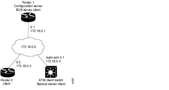
The following examples show how to configure two Cisco 4500 routers and one ATM switch router for one emulated LAN with fault tolerance. Configurations for both Ethernet and Token Ring emulated LANs are shown.
Router 1 contains the LECS, LES, BUS, and an LEC. Router 2 contains only an LEC. The ATM switch router contains the backup LECS and the backup LES for this emulated LAN, along with another LEC (see Figure 13-4).
Figure 13-4 Single Emulated LAN with Backup LANE Example Network
This example shows how to accept all default settings provided. For example, it does not explicitly set ATM addresses for the different LANE components that are also on the router. Membership in this emulated LAN is not restricted.
Ethernet Example
Router 1
router1# show lane default-atm-addressesinterface ATM0:LANE Client: 47.00918100000000603E7B2001.00000C407572.**LANE Server: 47.00918100000000603E7B2001.00000C407573.**LANE Bus: 47.00918100000000603E7B2001.00000C407574.**LANE Config Server: 47.00918100000000603E7B2001.00000C407575.00note: ** is the subinterface number byte in hexATM Switch Router
Switch# show lane default-atm-addressinterface ATM2/0/0:LANE Client: 47.00918100000000603E7B2001.00603E7B2002.**LANE Server: 47.00918100000000603E7B2001.00603E7B2003.**LANE Bus: 47.00918100000000603E7B2001.00603E7B2004.**LANE Config Server: 47.00918100000000603E7B2001.00603E7B2005.00note: ** is the subinterface number byte in hexSwitch# configure terminalEnter configuration commands, one per line. End with CNTL/Z.Switch(config)# atm lecs-address-default 47.00918100000000603E7B2001.00000C407575.00Switch(config)# atm lecs-address-default 47.00918100000000603E7B2001.00603E7B2005.00Switch(config)# endSwitch#Router 1
router1# configure terminalEnter configuration commands, one per line. End with CNTL/Z.router1(config)# lane database example1router1(lane-config-database)# name eng server-atm-address 47.00918100000000603E7B2001.00000C407573.01router1(lane-config-database)# name eng server-atm-address 47.00918100000000603E7B2001.00603E7B2003.01router1(lane-config-database)# default-name engrouter1(lane-config-database)# exitrouter1(config)# interface atm 3/0router1(config-if)# atm pvc 1 0 5 qsaalrouter1(config-if)# atm pvc 2 0 16 ilmirouter1(config-if)# lane config auto-config-atm-addressrouter1(config-if)# lane config database example1router1(config-if)#%LANE-5-UPDOWN: ATM0 database example1: LE Config Server (LECS) changed state to uprouter1(config-if)# interface atm 3/0.1router1(config-subif)# ip address 172.16.0.1 255.255.0.0router1(config-subif)# lane server-bus ethernet engrouter1(config-subif)# lane client ethernet engrouter1(config-subif)#%LANE-5-UPDOWN: ATM0.1 elan eng: LE Client changed state to uprouter1(config-subif)# endrouter1#ATM Switch Router
Switch# configure terminalEnter configuration commands, one per line. End with CNTL/Z.Switch(config)# lane database example1_backupSwitch(lane-config-database)# name eng server-atm-address 47.00918100000000603E7B2001.00000C407573.01Switch(lane-config-database)# name eng server-atm-address 47.00918100000000603E7B2001.00603E7B2003.01Switch(lane-config-database)# default-name engSwitch(lane-config-database)# exitSwitch(config)# interface atm 0Switch(config-if)# lane config auto-config-atm-addressSwitch(config-if)# lane config database example1_backupSwitch(config-if)#%LANE-5-UPDOWN: ATM2/0/0 database example1_backup: LE Config Server (LECS) changed state to up%LANE-6-LECS_INFO: ATM2/0/0: started listening on the well known LECS address%LANE-6-LECS_INFO: LECS on interface ATM2/0/0 became a BACKUP%LANE-6-LECS_INFO: ATM2/0/0: stopped listening on the well known LECS addressSwitch(config-if)# interface atm 0.1Switch(config-subif)# ip address 172.16.0.4 255.255.0.0Switch(config-subif)# lane server-bus ethernet engSwitch(config-subif)#%LANE-5-UPDOWN: ATM2/0/0.1 elan eng: LE Server/BUS changed state to upSwitch(config-subif)# lane client ethernet engSwitch(config-subif)#%LANE-5-UPDOWN: ATM2/0/0.1 elan eng: LE Client changed state to upSwitch(config-subif)# endSwitch#Router 2
router2# configure terminalEnter configuration commands, one per line. End with CNTL/Z.router2(config)# interface atm 3/0router2(config-if)# atm pvc 1 0 5 qsaalrouter2(config-if)# atm pvc 2 0 16 ilmirouter2(config-if)# interface atm 3/0.2router2(config-subif)# ip address 172.16.0.3 255.255.0.0router2(config-subif)# lane client ethernet engrouter2(config-subif)#%LANE-5-UPDOWN: ATM0.2 elan : LE Client changed state to uprouter2(config-subif)# endrouter2#Token Ring Example (Catalyst 8510 MSR and LightStream 1010)
Router 1
router1# show lane default-atm-addressesinterface ATM3/0:LANE Client: 47.00918100000000603E7B2001.00000C407572.**LANE Server: 47.00918100000000603E7B2001.00000C407573.**LANE Bus: 47.00918100000000603E7B2001.00000C407574.**LANE Config Server: 47.00918100000000603E7B2001.00000C407575.00note: ** is the subinterface number byte in hexATM Switch
Switch# show lane default-atm-addressinterface ATM2/0/0:LANE Client: 47.00918100000000603E7B2001.00603E7B2002.**LANE Server: 47.00918100000000603E7B2001.00603E7B2003.**LANE Bus: 47.00918100000000603E7B2001.00603E7B2004.**LANE Config Server: 47.00918100000000603E7B2001.00603E7B2005.00note: ** is the subinterface number byte in hexSwitch# configure terminalEnter configuration commands, one per line. End with CNTL/Z.Switch(config)# atm lecs-address-default 47.00918100000000603E7B2001.00000C407575.00Switch(config)# atm lecs-address-default 47.00918100000000603E7B2001.00603E7B2005.00Switch(config)# endSwitch#Router 1
router1# configure terminalEnter configuration commands, one per line. End with CNTL/Z.router1(config)# lane database example1router1(lane-config-database)# name eng server-atm-address 47.00918100000000603E7B2001.00000C407573.01router1(lane-config-database)# name eng server-atm-address 47.00918100000000603E7B2001.00603E7B2003.01router1(lane-config-database)# name eng local-seg-id 2048router1(lane-config-database)# default-name engrouter1(lane-config-database)# exitrouter1(config)# interface atm 3/0router1(config-if)# atm pvc 1 0 5 qsaalrouter1(config-if)# atm pvc 2 0 16 ilmirouter1(config-if)# lane config auto-config-atm-addressrouter1(config-if)# lane config database example1router1(config-if)#%LANE-5-UPDOWN: ATM0 database example1: LE Config Server (LECS) changed state to uprouter1(config-if)# interface atm 3/0.1router1(config-subif)# ip address 172.16.0.1 255.255.0.0router1(config-subif)# lane server-bus tokenring engrouter1(config-subif)# lane client tokenring engrouter1(config-subif)#%LANE-5-UPDOWN: ATM0.1 elan eng: LE Client changed state to uprouter1(config-subif)# endrouter1#ATM Switch
Switch# configure terminalEnter configuration commands, one per line. End with CNTL/Z.Switch(config)# lane database example1_backupSwitch(lane-config-database)# name eng server-atm-address 47.00918100000000603E7B2001.00000C407573.01Switch(lane-config-database)# name eng server-atm-address 47.00918100000000603E7B2001.00603E7B2003.01Switch(lane-config-database)# name eng local-seg-id 2048Switch(lane-config-database)# default-name engSwitch(lane-config-database)# exitSwitch(config)# interface atm 0Switch(config-if)# lane config auto-config-atm-addressSwitch(config-if)# lane config database example1_backupSwitch(config-if)#%LANE-5-UPDOWN: ATM2/0/0 database example1_backup: LE Config Server (LECS) changed state to up%LANE-6-LECS_INFO: ATM2/0/0: started listening on the well known LECS address%LANE-6-LECS_INFO: LECS on interface ATM2/0/0 became a BACKUP%LANE-6-LECS_INFO: ATM2/0/0: stopped listening on the well known LECS addressSwitch(config-if)# interface atm 0.1Switch(config-subif)# ip address 172.16.0.4 255.255.0.0Switch(config-subif)# lane server-bus tokenring engSwitch(config-subif)#%LANE-5-UPDOWN: ATM2/0/0.1 elan eng: LE Server/BUS changed state to upSwitch(config-subif)# lane client tokenring engSwitch(config-subif)#%LANE-5-UPDOWN: ATM2/0/0.1 elan eng: LE Client changed state to upSwitch(config-subif)# endSwitch#Router 2
router2# configure terminalEnter configuration commands, one per line. End with CNTL/Z.router2(config)# interface atm 3/0router2(config-if)# atm pvc 1 0 5 qsaalrouter2(config-if)# atm pvc 2 0 16 ilmirouter2(config-if)# interface atm 3/0.2router2(config-subif)# ip address 172.16.0.3 255.255.0.0router2(config-subif)# lane client tokenring engrouter2(config-subif)#%LANE-5-UPDOWN: ATM0.2 elan : LE Client changed state to uprouter2(config-subif)# endrouter2#Displaying the LECS Configuration on the ATM Switch Router
The following example shows the show lane config command display for the LECS (Ethernet and Token Ring):
Switch# show lane configLE Config Server ATM2/0/0 config table: example1_backupAdmin: up State: operationalLECS Mastership State: backuplist of global LECS addresses (45 seconds to update):47.00918100000000603E7B2001.00000C407575.00 incoming call (vcd 88)47.00918100000000603E7B2001.00603E7B2005.00 <-------- meATM Address of this LECS: 47.00918100000000603E7B2001.00603E7B2005.00 (auto)vcd rxCnt txCnt callingParty88 0 0 47.00918100000000603E7B2001.00000C407575.00 LECScumulative total number of unrecognized packets received so far: 0cumulative total number of config requests received so far: 0cumulative total number of config failures so far: 0Displaying the LES Configuration on the ATM Switch Router
The following example shows the show lane server command display for the Ethernet LES:
Switch# show lane serverLE Server ATM2/0/0.1 ELAN name: eng Admin: up State: operationaltype: ethernet Max Frame Size: 1516ATM address: 47.00918100000000603E7B2001.00603E7B2003.01LECS used: 47.00918100000000603E7B2001.00000C407575.00 connected, vcd 95The following example shows the show lane server command display for the Token Ring LANE server:
Switch# show lane serverLE Server ATM2/0/0.1 ELAN name: eng Admin: up State: operationaltype: token ring Max Frame Size: 4544 Segment ID: 2048ATM address: 47.00918100000000603E7B2001.00603E7B2003.01LECS used: 47.00918100000000603E7B2001.00000C407575.00 connected, vcd 95Default Configuration for a Token Ring ELAN with IP Source Routing (Catalyst 8510 MSR and LightStream 1010)
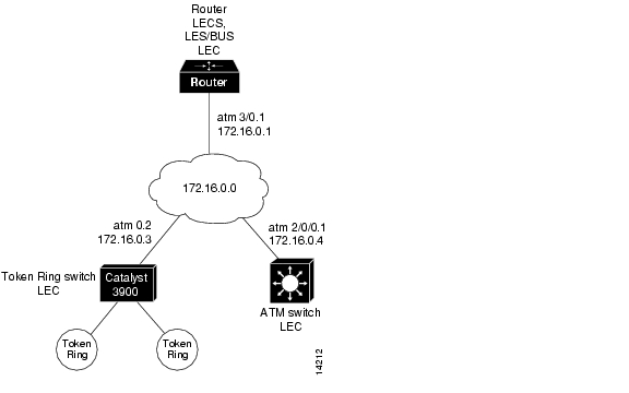
The following example shows how to configure a single emulated Token Ring LAN using a Cisco 4500 router and an ATM switch with IP source routing across a source-route bridged network. In this example, the emulated Token Ring LAN is source-route bridged to two physical Token Rings.
The router contains the LECS, LES, BUS, and an LEC. Both the ATM switch and Token Ring switch contain an LEC for the emulated LAN. This example uses all LANE default settings. For example, it does not explicitly set ATM addresses for the different LANE components that are colocated on the router. Membership in this emulated LAN is not restricted (see Figure 13-5).
Figure 13-5 Single Emulated Token Ring LAN with Token Ring Switch
Router
router# show lane default-atm-addressesinterface ATM0:LANE Client: 47.00918100000000603E7B2001.00000C407572.**LANE Server: 47.00918100000000603E7B2001.00000C407573.**LANE Bus: 47.00918100000000603E7B2001.00000C407574.**LANE Config Server: 47.00918100000000603E7B2001.00000C407575.00note: ** is the subinterface number byte in hexATM Switch
Switch# configure terminalEnter configuration commands, one per line. End with CNTL/Z.Switch(config)# atm lecs-address-default 47.00918100000000603E7B2001.00000C407575.00Switch(config)# endSwitch#Router
router# configure terminalEnter configuration commands, one per line. End with CNTL/Z.router(config)# lane database example1router(lane-config-database)# name eng server-atm-address 47.00918100000000603E7B2001.00000C407573.01router(lane-config-database)# name eng local-seg-id 2048router(lane-config-database)# default-name engrouter(lane-config-database)# exitrouter(config)# interface atm 3/0router(config-if)# atm pvc 1 0 5 qsaalrouter(config-if)# atm pvc 2 0 16 ilmirouter(config-if)# lane config auto-config-atm-addressrouter(config-if)# lane config database example1router(config-if)#%LANE-5-UPDOWN: ATM0 database example1: LE Config Server (LECS) changed state to uprouter(config-if)# interface atm 3/0.1router(config-subif)# ip address 172.16.0.1 255.255.0.0router(config-subif)# lane server-bus tokenring engrouter(config-subif)# lane client tokenring engrouter(config-subif)#%LANE-5-UPDOWN: ATM0.1 elan eng: LE Client changed state to uprouter(config-subif)# endrouter#ATM Switch
Switch# configure terminalEnter configuration commands, one per line. End with CNTL/Z.Switch(config)# interface atm 0.1Switch(config-subif)# ip address 172.16.0.4 255.255.0.0Switch(config-subif)# lane client tokenring engSwitch(config-subif)# multiring ipSwitch(config-subif)#%LANE-5-UPDOWN: ATM2/0/0.1 elan : LE Client changed state to upSwitch(config-subif)# endSwitch#
![]()
![]()
![]()
![]()
![]()
![]()
![]()
![]()
Posted: Mon Oct 11 09:13:00 PDT 2004
All contents are Copyright © 1992--2004 Cisco Systems, Inc. All rights reserved.
Important Notices and Privacy Statement.