|
|

Table Of Contents
Configuring Virtual Connections
Characteristics and Types of Virtual Connections
Configuring Virtual Channel Connections
Deleting VCCs from an Interface
Configuring Terminating PVC Connections
Displaying the Terminating PVC Connections
Deleting PVPs from an Interface
Configuring Point-to-Multipoint PVC Connections
Displaying Point-to-Multipoint PVC Configuration
Configuring Point-to-Multipoint PVP Connections
Displaying Point-to-Multipoint PVP Configuration
Configuring Soft PVC Connections
Guidelines for Creating Soft PVCs
Displaying Soft PVC Configuration
Configuring Soft PVP Connections
Displaying Soft PVP Connections
Configuring the Soft PVP or Soft PVC Route Optimization Feature
Enabling Soft PVP or Soft PVC Route Optimization
Configuring a Soft PVP/PVC Interface with Route Optimization
Displaying an Interface Route Optimization Configuration
Configuring Soft PVCs with Explicit Paths
Changing Explicit Paths for an Existing Soft PVC
Displaying Explicit Path for Soft PVC Connections
Configuring Nondefault Well-Known PVCs
Overview of Nondefault PVC Configuration
Configuring a VPI/VCI Range for SVPs and SVCs
Displaying the VPI/VCI Range Configuration
Configuring a VP Tunnel for a Single Service Category
Configuring a Shaped VP Tunnel
Configuring a Hierarchical VP Tunnel for Multiple Service Categories
Configuring an End-Point PVC to a PVP Tunnel
Configuring Signalling VPCI for VP Tunnels
Configuring Interface and Connection Snooping
Configuring Interface Snooping
Configuring Per-Connection Snooping
Displaying Per-connection Snooping
Configuring Virtual Connections
This chapter describes how to configure virtual connections (VCs) in a typical ATM network after autoconfiguration has established the default network connections. The network configuration modifications described in this chapter are used to optimize your ATM network operation.
Note
This chapter provides advanced configuration instructions for the Catalyst 8540 MSR, Catalyst 8510 MSR, and LightStream 1010 ATM switch routers. For an overview of virtual connection types and applications, refer to the Guide to ATM Technology. For complete descriptions of the commands mentioned in this chapter, refer to the ATM Switch Router Command Reference publication.
The tasks to configure virtual connections are described in the following sections:
•
•
•
•
•
•
•
•
•
•
•
•
Characteristics and Types of Virtual Connections
This section lists the various virtual connections (VC) types in Table 6-1.
Configuring Virtual Channel Connections
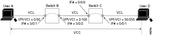
This section describes configuring virtual channel connections (VCCs) on the ATM switch router. A VCC is established as a bidirectional facility to transfer ATM traffic between two ATM layer users. Figure 6-1 shows an example VCC between ATM user A and user D.
An end-to-end VCC, as shown in Figure 6-1 between user A and user D, has two parts:
•
•
The common endpoint between an internal connection and a link occurs at the switch interface. The endpoint of the internal connection is also referred to as a connection leg or half-leg. A cross-connect connects two legs together.
Figure 6-1 VCC Example
Note
To configure a point-to-point VCC, perform the following steps, beginning in global configuration mode:
Step 1
Switch(config)# interface atm card/subcard/port
Switch(config-if)#
Selects the interface to be configured.
Step 2
Switch(config-if)# atm pvc vpi-A [vci-A | any-vci1 ] [rx-cttr index] [tx-cttr index] interface atm card/subcard/port[.vpt#] vpi-B [vci-B | any-vci1]
Configures the PVC.
1 The any-vci parameter is only available for interface atm0.
Note
Note
Examples
The following example shows how to configure the internal cross-connect PVC on Switch B between interface ATM 3/0/1 (VPI = 0, VCI = 50) and interface ATM 3/0/2 (VPI = 2, VCI = 100) (see Figure 6-1):
Switch-B(config)# interface atm 3/0/1Switch-B(config-if)# atm pvc 0 50 interface atm 3/0/2 2 100The following example shows how to configure the internal cross-connect PVC on Switch C between interface ATM 0/0/0, VPI = 2, VCI = 100, and interface ATM 0/0/1, VPI 50, VCI = 255:
Switch-C(config)# interface atm 0/0/0Switch-C(config-if)# atm pvc 2 100 interface atm 0/0/1 50 255Each subsequent VC cross-connection and link must be configured until the VC is terminated to create the entire VCC.
Note
Displaying VCCs
To show the VCC configuration, use the following EXEC commands:
show atm interface [atm card/subcard/port]
Shows the ATM interface configuration.
show atm vc [interface atm card/subcard/port vpi vci]
Shows the PVC interface configuration.
Note
Examples
The following example shows the Switch B PVC configuration on ATM interface 3/0/1:
Switch-B# show atm interfaceInterface: ATM3/0/1 Port-type: oc3suniIF Status: UP Admin Status: upAuto-config: enabled AutoCfgState: completedIF-Side: Network IF-type: NNIUni-type: not applicable Uni-version: not applicableMax-VPI-bits: 8 Max-VCI-bits: 14Max-VP: 255 Max-VC: 16383ConfMaxSvpcVpi: 255 CurrMaxSvpcVpi: 255ConfMaxSvccVpi: 255 CurrMaxSvccVpi: 255ConfMinSvccVci: 35 CurrMinSvccVci: 35Svc Upc Intent: pass Signalling: EnabledATM Address for Soft VC: 47.0091.8100.0000.00e0.4fac.b401.4000.0c80.8000.00Configured virtual links:PVCLs SoftVCLs SVCLs TVCLs PVPLs SoftVPLs SVPLs Total-Cfgd Inst-Conns4 0 0 0 0 0 0 4 2Logical ports(VP-tunnels): 0Input cells: 264330 Output cells: 2734715 minute input rate: 0 bits/sec, 0 cells/sec5 minute output rate: 0 bits/sec, 0 cells/secInput AAL5 pkts: 172613, Output AAL5 pkts: 177185, AAL5 crc errors: 0The following example shows the Switch B PVC configuration on ATM interface 3/0/1:
Switch-B# show atm vc interface atm 3/0/1Interface VPI VCI Type X-Interface X-VPI X-VCI Encap StatusATM3/0/1 0 5 PVC ATM0 0 57 QSAAL UPATM3/0/1 0 16 PVC ATM0 0 37 ILMI UPATM3/0/1 0 18 PVC ATM0 0 73 PNNI UPATM3/0/1 0 50 PVC ATM3/0/2 2 100 UPATM3/0/1 1 50 PVC ATM0 0 80 SNAP UPThe following example shows the Switch B PVC configuration on ATM interface 3/0/1, VPI = 0, VCI = 50, with the switch processor feature card installed:
Switch-B# show atm vc interface atm 3/0/1 0 50Interface: ATM3/0/1, Type: oc3suniVPI = 0 VCI = 50Status: UPTime-since-last-status-change: 4d02hConnection-type: PVCCast-type: point-to-pointPacket-discard-option: disabledUsage-Parameter-Control (UPC): passWrr weight: 32Number of OAM-configured connections: 0OAM-configuration: disabledOAM-states: Not-applicableCross-connect-interface: ATM3/0/2, Type: oc3suniCross-connect-VPI = 2Cross-connect-VCI = 100Cross-connect-UPC: passCross-connect OAM-configuration: disabledCross-connect OAM-state: Not-applicableThreshold Group: 5, Cells queued: 0Rx cells: 0, Tx cells: 0Tx Clp0:0, Tx Clp1: 0Rx Clp0:0, Rx Clp1: 0Rx Upc Violations:0, Rx cell drops:0Rx Clp0 q full drops:0, Rx Clp1 qthresh drops:0Rx connection-traffic-table-index: 1Rx service-category: UBR (Unspecified Bit Rate)Rx pcr-clp01: 7113539Rx scr-clp01: noneRx mcr-clp01: noneRx cdvt: 1024 (from default for interface)Rx mbs: noneTx connection-traffic-table-index: 1Tx service-category: UBR (Unspecified Bit Rate)Tx pcr-clp01: 7113539Tx scr-clp01: noneTx mcr-clp01: noneTx cdvt: noneTx mbs: noneDeleting VCCs from an Interface
This section describes how to delete a VCC configured on an interface. To delete a VCC, perform the following steps, beginning in global configuration mode:
Step 1
Switch(config)# interface atm card/subcard/port
Switch(config-if)#
Selects the interface to be configured.
Step 2
Switch(config-if)# no atm pvc vpi vci
Deletes the PVC.
Example
The following example shows how to delete the VCC on ATM interface 3/0/0, VPI = 20, VCI = 200:
Switch(config-if)# interface atm 3/0/0Switch(config-if)# no atm pvc 20 200Confirming VCC Deletion
To confirm the deletion of a VCC from an interface, use the following EXEC command before and after deleting the VCC:
show atm vc interface atm card/subcard/port [vpi vci]
Shows the PVCs configured on the interface.
Example
The following example shows how to confirm that the VCC is deleted from the interface:
Switch# show atm vc interface atm 3/0/0Interface VPI VCI Type X-Interface X-VPI X-VCI Encap StatusATM3/0/0 0 5 PVC ATM2/0/0 0 77 QSAAL UPATM3/0/0 0 16 PVC ATM2/0/0 0 55 ILMI UPATM3/0/0 0 18 PVC ATM2/0/0 0 152 PNNI UPATM3/0/0 0 34 PVC ATM2/0/0 0 151 NCDP UP
Switch# configure terminalSwitch(config)# interface atm 3/0/0Switch(config-if)# no atm pvc 20 200Switch(config-if)# endSwitch# show atm vc interface atm 3/0/0Interface VPI VCI Type X-Interface X-VPI X-VCI Encap StatusATM3/0/0 0 5 PVC ATM2/0/0 0 77 QSAAL UPATM3/0/0 0 16 PVC ATM2/0/0 0 55 ILMI UPATM3/0/0 0 18 PVC ATM2/0/0 0 152 PNNI UP
Configuring Terminating PVC Connections
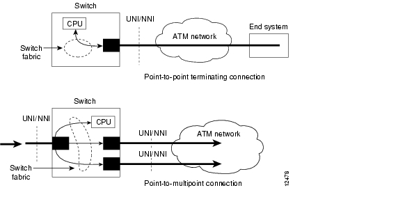
This section describes configuring point-to-point and point-to-multipoint terminating permanent virtual channel (PVC) connections. Terminating connections provide the connection to the ATM switch router's route processor for LAN emulation (LANE), IP over ATM, and control channels for Integrated Local Management Interface (ILMI), signalling, and Private Network-Network Interface (PNNI) plus network management.
Figure 6-2 shows an example of transit and terminating connections.
Figure 6-2 Terminating PVC Types
Point-to-point and point-to-multipoint are two types of terminating connections. Both terminating connections are configured using the same commands as transit connections (discussed in the previous sections). However, all switch terminating connections use interface atm0 to connect to the route processor.
Note
To configure both point-to-point and point-to-multipoint terminating PVC connections, perform the following steps, beginning in global configuration mode:
Step 1
Switch(config)# interface atm card-A/subcard-A/port-A[.vpt#]
Switch(config-if)#
Selects the interface to be configured.
Step 2
Switch(config-if)# atm pvc vpi-A [vci-A | any-vci1 ] [cast-type type] [rx-cttr index]
[tx-cttr index] interface atm card-B/subcard-B/port-B[.vpt#] vpi-B [vci-B | any-vci1] [encap type] [cast-type type]Configures the PVC between ATM switch router connections.
1 The any-vci feature is only available for interface atm 0.
When configuring point-to-multipoint PVC connections using the atm pvc command, the root point is port A and the leaf points are port B.
Note
Examples
The following example shows how to configure the internal cross-connect PVC between interface ATM 3/0/1, VPI = 1, VCI = 50, and the terminating connection at the route processor interface ATM 0, VPI = 0, and VCI unspecified:
Switch-B(config)# interface atm 3/0/1Switch-B(config-if)# atm pvc 1 50 interface atm0 0 any-vci encap aal5snapThe following example shows how to configure the route processor leg of any terminating PVC:
Switch(config)# interface atm0Switch(config-if)# atm pvc 0 any-vciWhen configuring the route processor leg of a PVC that is not a tunnel, the VPI should be configured as 0. The preferred method of VCI configuration is to select the any-vci parameter, unless a specific VCI is needed as a parameter in another command, such as map-list.
Note
Displaying the Terminating PVC Connections
To display the terminating PVC configuration VCs on the interface, use the following EXEC command:
show atm vc interface atm card/subcard/port vpi vci
Shows the PVC configured on the interface.
See the "Displaying VCCs" section for examples of the show atm vc commands.
Configuring PVP Connections
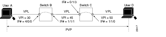
This section describes configuring a permanent virtual path (PVP) connection. Figure 6-3 shows an example of PVPs configured through the ATM switch routers.
Figure 6-3 Virtual Path Connection Example
To configure a PVP connection, perform the following steps, beginning in global configuration mode:
Note
Note
Examples
The following example shows how to configure the internal cross-connect PVP within Switch B between interfaces 4/0/0, VPI = 30, and interface ATM 1/1/1, VPI = 45:
Switch-B(config)# interface atm 4/0/0Switch-B(config-if)# atm pvp 30 interface atm 1/1/1 45The following example shows how to configure the internal cross-connect PVP within Switch C between interfaces 0/1/3, VPI = 45, and interface ATM 1/1/0, VPI = 50:
Switch-C(config)# interface atm 0/1/3LS1010(config-if)# atm pvp 45 interface atm 1/1/0 50Each subsequent PVP cross connection and link must be configured until the VP is terminated to create the entire PVP.
Displaying PVP Configuration
To show the ATM interface configuration, use the following EXEC command:
Example
The following example shows the PVP configuration of Switch B:
Switch-B# show atm vpInterface VPI Type X-Interface X-VPI StatusATM1/1/1 45 PVP ATM4/0/0 30 UPATM4/0/0 30 PVP ATM1/1/1 45 UPThe following example shows the PVP configuration of Switch B with the switch processor feature card installed:
Switch-B# show atm vp interface atm 4/0/0 30Interface: ATM4/0/0, Type: ds3suniVPI = 30Status: UPTime-since-last-status-change: 00:09:02Connection-type: PVPCast-type: point-to-pointUsage-Parameter-Control (UPC): passWrr weight: 2Number of OAM-configured connections: 0OAM-configuration: disabledOAM-states: Not-applicableCross-connect-interface: ATM1/1/1, Type: oc3suniCross-connect-VPI = 45Cross-connect-UPC: passCross-connect OAM-configuration: disabledCross-connect OAM-state: Not-applicableThreshold Group: 5, Cells queued: 0Rx cells: 0, Tx cells: 0Tx Clp0:0, Tx Clp1: 0Rx Clp0:0, Rx Clp1: 0Rx Upc Violations:0, Rx cell drops:0Rx Clp0 q full drops:0, Rx Clp1 qthresh drops:0Rx connection-traffic-table-index: 1Rx service-category: UBR (Unspecified Bit Rate)Rx pcr-clp01: 7113539Rx scr-clp01: noneRx mcr-clp01: noneRx cdvt: 1024 (from default for interface)Rx mbs: noneTx connection-traffic-table-index: 1Tx service-category: UBR (Unspecified Bit Rate)Tx pcr-clp01: 7113539Tx scr-clp01: noneTx mcr-clp01: noneTx cdvt: noneTx mbs: noneDeleting PVPs from an Interface
This section describes how to delete a PVP configured on an interface. To delete a PVP, perform the following steps, beginning in global configuration mode:
Step 1
Switch(config)# interface atm card/subcard/port
Switch(config-if)#
Selects the interface to be configured.
Step 2
Switch(config-if)# no atm pvp vpi
Deletes the PVP.
Example
The following example shows how to delete the PVP on ATM interface 1/1/0, VPI = 200:
Switch(config-if)# interface atm 1/1/0Switch(config-if)# no atm pvp 200Confirming PVP Deletion
To confirm the deletion of a PVP from an interface, use the following EXEC command before and after deleting the PVP:
show atm vp interface atm [card/subcard/port vpi]
Shows the PVCs configured on the interface.
Example
The following example shows how to confirm that the PVP is deleted from the interface:
Switch# show atm vpInterface VPI Type X-Interface X-VPI StatusATM1/1/0 113 PVP TUNNELATM1/1/1 1 PVP SHAPED TUNNELSwitch# configure terminalSwitch(config)# interface atm 1/1/0Switch(config-if)# no atm pvp 200Switch(config-if)# endSwitch# show atm vpInterface VPI Type X-Interface X-VPI StatusATM1/1/0 113 PVP TUNNELATM1/1/1 1 PVP SHAPED TUNNELSwitch#Configuring Point-to-Multipoint PVC Connections
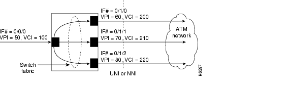
This section describes configuring point-to-multipoint PVC connections. In Figure 6-4, cells entering the ATM switch router at the root point (on the left side at interface ATM 0/0/0, VPI = 50, VCI = 100) are duplicated and switched to the leaf points (output interfaces) on the right side of the figure.
Figure 6-4 Point-to-Multipoint PVC Example
Note
To configure the point-to-multipoint PVC connections shown in Figure 6-4, perform the following steps, beginning in global configuration mode:
To configure the point-to-multipoint PVC connections using the atm pvc command, the root point is port A and the leaf points are port B.
Note
Examples
The following example shows how to configure the root-point PVC on ATM switch router interface ATM 0/0/0, VPI = 50, VCI = 100, to the leaf-point interfaces (see Figure 6-4):
Switch(config)# interface atm 0/0/0Switch(config-if)# atm pvc 50 100 cast-type p2mp-root interface atm 0/1/0 60 200 cast-type p2mp-leafSwitch(config-if)# atm pvc 50 100 cast-type p2mp-root interface atm 0/1/1 70 210 cast-type p2mp-leafSwitch(config-if)# atm pvc 50 100 cast-type p2mp-root interface atm 0/1/2 80 220 cast-type p2mp-leafDisplaying Point-to-Multipoint PVC Configuration
To display the point-to-multipoint PVC configuration, use the following EXEC mode command:
show atm vc interface atm card/subcard/port
Shows the PVCs configured on the interface.
show atm vc interface atm card/subcard/port vpi vci
Shows the PVCs configured on the interface.
Examples
The following example shows the PVC configuration of the point-to-multipoint connections on ATM interface 0/0/0:
Switch# show atm vc interface atm 0/0/0Interface VPI VCI Type X-Interface X-VPI X-VCI Encap StatusATM0/0/0 0 5 PVC ATM2/0/0 0 70 QSAAL UPATM0/0/0 0 16 PVC ATM2/0/0 0 46 ILMI UPATM0/0/0 0 18 PVC ATM2/0/0 0 120 PNNI UPATM0/0/0 0 34 PVC ATM2/0/0 0 192 NCDP UPATM0/0/0 50 100 PVC ATM0/1/0 60 200 UPATM0/1/1 70 210 UPATM0/1/2 80 220 UPThe following example shows the VC configuration on interface ATM 0/0/0, VPI = 50, VCI = 100, with the switch processor feature card installed:
Switch# show atm vc interface atm 0/0/0 50 100Interface: ATM0/0/0, Type: oc3suniVPI = 50 VCI = 100Status: UPTime-since-last-status-change: 00:07:06Connection-type: PVCCast-type: point-to-multipoint-rootPacket-discard-option: disabledUsage-Parameter-Control (UPC): passWrr weight: 32Number of OAM-configured connections: 0OAM-configuration: disabledOAM-states: Not-applicableCross-connect-interface: ATM0/1/0, Type: oc3suniCross-connect-VPI = 60Cross-connect-VCI = 200Cross-connect-UPC: passCross-connect OAM-configuration: disabledCross-connect OAM-state: Not-applicableCross-connect-interface: ATM0/1/1Cross-connect-VPI = 70Cross-connect-VCI = 210Cross-connect-interface: ATM0/1/2Cross-connect-VPI = 80Cross-connect-VCI = 220Threshold Group: 5, Cells queued: 0Rx cells: 0, Tx cells: 0Tx Clp0:0, Tx Clp1: 0Rx Clp0:0, Rx Clp1: 0Rx Upc Violations:0, Rx cell drops:0Rx Clp0 q full drops:0, Rx Clp1 qthresh drops:0Rx connection-traffic-table-index: 1Rx service-category: UBR (Unspecified Bit Rate)Rx pcr-clp01: 7113539Rx scr-clp01: noneRx mcr-clp01: noneRx cdvt: 1024 (from default for interface)Rx mbs: noneTx connection-traffic-table-index: 1Tx service-category: UBR (Unspecified Bit Rate)Tx pcr-clp01: 7113539Tx scr-clp01: noneTx mcr-clp01: noneTx cdvt: noneTx mbs: noneConfiguring Point-to-Multipoint PVP Connections
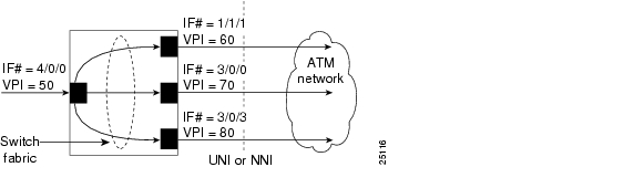
This section describes configuring point-to-multipoint PVP connections. Figure 6-5 provides an example of point-to-multipoint PVP connections.
Figure 6-5 Point-to-Multipoint PVP Example
In Figure 6-5, cells entering the ATM switch router at the root point (the left side at interface ATM 4/0/0), VPI = 50, are duplicated and switched to the leaf points (output interfaces), on the right side of the figure.
To configure point-to-multipoint PVP connections, perform the following steps, beginning in global configuration mode:
To configure the point-to-multipoint PVP connections using the atm pvp command, the root point is port A and the leaf points are port B.
Note
Examples
The following example shows how to configure the root-point PVP on ATM switch router interface ATM 4/0/0 (VPI = 50), to the leaf point interfaces ATM 1/1/1 (VPI = 60), ATM 3/0/0 (VPI = 70), and ATM 3/0/3 (VPI = 80) (see Figure 6-5):
Switch(config)# interface atm 4/0/0Switch(config-if)# atm pvp 50 cast-type p2mp-root interface atm 1/1/1 60 cast-type p2mp-leafSwitch(config-if)# atm pvp 50 cast-type p2mp-root interface atm 3/0/0 70 cast-type p2mp-leafSwitch(config-if)# atm pvp 50 cast-type p2mp-root interface atm 3/0/3 80 cast-type p2mp-leafDisplaying Point-to-Multipoint PVP Configuration
To display the ATM interface configuration, use the following EXEC command:
Examples
The following example shows the PVP configuration of the point-to-multipoint PVP connections on ATM interface 4/0/0:
Switch# show atm vp interface atm 4/0/0Interface VPI Type X-Interface X-VPI StatusATM4/0/0 50 PVP ATM1/1/1 60 UPATM3/0/0 70 UPATM3/0/3 80 UPThe following example shows the PVP configuration of the point-to-multipoint PVP connections on ATM interface 4/0/0, VPI = 50, with the switch processor feature card installed:
Switch# show atm vp interface atm 4/0/0 50Interface: ATM4/0/0, Type: ds3suniVPI = 50Status: UPTime-since-last-status-change: 00:01:51Connection-type: PVPCast-type: point-to-multipoint-rootUsage-Parameter-Control (UPC): passWrr weight: 2Number of OAM-configured connections: 0OAM-configuration: disabledOAM-states: Not-applicableCross-connect-interface: ATM1/1/1, Type: oc3suniCross-connect-VPI = 60Cross-connect-UPC: passCross-connect OAM-configuration: disabledCross-connect OAM-state: Not-applicableCross-connect-interface: ATM3/0/0Cross-connect-VPI = 70Cross-connect-interface: ATM3/0/3Cross-connect-VPI = 80Threshold Group: 5, Cells queued: 0Rx cells: 0, Tx cells: 0Tx Clp0:0, Tx Clp1: 0Rx Clp0:0, Rx Clp1: 0Rx Upc Violations:0, Rx cell drops:0Rx Clp0 q full drops:0, Rx Clp1 qthresh drops:0Rx connection-traffic-table-index: 1Rx service-category: UBR (Unspecified Bit Rate)Rx pcr-clp01: 7113539Rx scr-clp01: noneRx mcr-clp01: noneRx cdvt: 1024 (from default for interface)Rx mbs: noneTx connection-traffic-table-index: 1Tx service-category: UBR (Unspecified Bit Rate)Tx pcr-clp01: 7113539Tx scr-clp01: noneTx mcr-clp01: noneTx cdvt: noneTx mbs: noneConfiguring Soft PVC Connections
This section describes configuring soft permanent virtual channel (PVC) connections, which provide the following features:
•
•
•
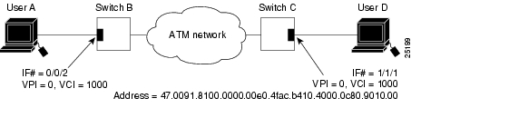
Figure 6-6 illustrates the soft PVC connections used in the following examples.
Figure 6-6 Soft PCV Connection Example
Guidelines for Creating Soft PVCs
Perform the following steps when you configure soft PVCs:
Step 1
Step 2
This decision is arbitrary—it makes no difference which port you define as the destination end of the circuit.
Step 3
Step 4
Step 5
Configuring Soft PVCs
To configure a soft PVC connection, perform the following steps, beginning in privileged EXEC mode:
Note
Examples
The following example shows the destination ATM address of the interface connected to User D:
Switch-C# show atm addresses
Switch Address(es):47.00918100000000400B0A2A81.00400B0A2A81.00 active47.00918100000000E04FACB401.00E04FACB401.00Soft VC Address(es):<Information deleted>47.0091.8100.0000.00e0.4fac.b401.4000.0c80.9000.00 ATM1/1/047.0091.8100.0000.00e0.4fac.b401.4000.0c80.9010.00 ATM1/1/147.0091.8100.0000.00e0.4fac.b401.4000.0c80.9020.00 ATM1/1/2<Information deleted>The following example shows how to configure a soft PVC on Switch B between interface ATM 0/0/2, source VPI = 0, VCI = 1000; and Switch C, destination VPI = 0, VCI = 1000 with a specified ATM address (see Figure 6-6):
Switch-B(config)# interface atm 0/0/2Switch-B(config-if)# atm soft-vc 0 1000 dest-address 47.0091.8100.0000.00e0.4fac.b401.4000.0c80.9010.00 0 1000Displaying Soft PVC Configuration
To display the soft PVC configuration at either end of a ATM switch router, use the following EXEC commands:
Examples
The following example shows the soft PVC configuration of Switch B, on interface ATM 0/0/2 out to the ATM network:
Switch-B# show atm vc interface atm 0/0/2Interface VPI VCI Type X-Interface X-VPI X-VCI Encap StatusATM0/0/2 0 5 PVC ATM0 0 45 QSAAL UPATM0/0/2 0 16 PVC ATM0 0 37 ILMI UPATM0/0/2 0 18 PVC ATM0 0 52 PNNI UPATM0/0/2 0 34 PVC ATM0 0 51 NCDP UPATM0/0/2 0 35 SVC ATM0/0/2 0 1000 UPThe following example shows the soft PVC configuration of Switch C, on interface ATM 1/1/1 out to the ATM network:
Switch-C# show atm vc interface atm 1/1/1Interface VPI VCI Type X-Interface X-VPI X-VCI Encap StatusATM1/1/1 0 5 PVC ATM2/0/0 0 74 QSAAL UPATM1/1/1 0 16 PVC ATM2/0/0 0 44 ILMI UPATM1/1/1 0 18 PVC ATM2/0/0 0 109 PNNI UPATM1/1/1 0 34 PVC ATM2/0/0 0 120 NCDP UPATM1/1/1 0 123 SVC ATM1/1/1 0 1000 UPATM1/1/1 2 100 PVC ATM2/0/0 0 103 SNAP UPThe following example shows the soft PVC configuration of Switch B, on interface ATM 0/0/2 (VPI = 0, VCI = 1000) out to the ATM network with the switch processor feature card installed:
Switch-B# show atm vc interface atm 0/0/2 0 1000Interface: ATM0/0/2, Type: oc3suniStatus: UPTime-since-last-status-change: 21:56:48Connection-type: SoftVCCast-type: point-to-pointSoft vc location: SourceRemote VPI: 0Remote VCI: 1000Soft vc call state: ActiveNumber of soft vc re-try attempts: 0First-retry-interval: 5000 millisecondsMaximum-retry-interval: 60000 millisecondsAggregate admin weight: 10080TIME STAMPS:Current Slot:2Outgoing Setup May 25 10:38:50.718Incoming Connect May 25 10:38:50.762Packet-discard-option: disabledUsage-Parameter-Control (UPC): passWrr weight: 2Number of OAM-configured connections: 0OAM-configuration: disabledOAM-states: Not-applicableCross-connect-interface: ATM0/0/2, Type: oc3suniCross-connect-VPI = 0Cross-connect-VCI = 35Cross-connect-UPC: passCross-connect OAM-configuration: disabledCross-connect OAM-state: Not-applicableThreshold Group: 5, Cells queued: 0Rx cells: 0, Tx cells: 0Tx Clp0:0, Tx Clp1: 0Rx Clp0:0, Rx Clp1: 0Rx Upc Violations:0, Rx cell drops:0Rx Clp0 q full drops:0, Rx Clp1 qthresh drops:0Rx connection-traffic-table-index: 1Rx service-category: UBR (Unspecified Bit Rate)Rx pcr-clp01: 7113539Rx scr-clp01: noneRx mcr-clp01: noneRx cdvt: 1024 (from default for interface)Rx mbs: noneTx connection-traffic-table-index: 1Tx service-category: UBR (Unspecified Bit Rate)Tx pcr-clp01: 7113539Tx scr-clp01: noneTx mcr-clp01: noneTx cdvt: noneTx mbs: noneConfiguring Soft PVP Connections
This section describes configuring soft permanent virtual path (PVP) connections, which provide the following features:
•
•
•
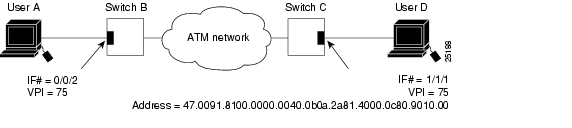
Figure 6-7 is an illustration of the soft PVP connections used in the examples in this section.
Figure 6-7 Soft PVP Connection Example
To configure a soft PVP connection, perform the following steps, beginning in global configuration mode:
The row index for rx-cttr and tx-cttr must be configured before using this optional parameter. See the "Configuring the Connection Traffic Table" section on page 8-10.
Example
The following example shows how to configure a soft PVP on Switch B between interface ATM 0/0/2, source VPI = 75; and Switch C, destination VPI = 75, with a specified ATM address (see Figure 6-7):
Switch-B(config)# interface atm 0/0/2Switch-B(config-if)# atm soft-vp 75 dest-address 47.0091.8100.0000.0040.0b0a.2a81.4000.0c80.9010.00 75Displaying Soft PVP Connections
To display the ATM soft PVP configuration, use the following EXEC command:
Examples
The following example shows the soft PVP configuration at Switch B, on interface ATM 0/0/2 out to the ATM network:
Switch-B# show atm vpInterface VPI Type X-Interface X-VPI StatusATM0/0/2 1 SVP ATM0/0/2 75 UPATM0/0/2 75 SoftVP ATM0/0/2 1 UPThe following example shows the soft PVP configuration on interface ATM 1/1/1 at Switch C out to the ATM network:
Switch-C# show atm vpInterface VPI Type X-Interface X-VPI StatusATM1/1/1 1 SVP ATM1/1/1 75 UPATM1/1/1 75 SoftVP ATM1/1/1 1 UPThe following example shows the soft PVP configuration at Switch B on interface ATM 0/0/2 (VPI = 75) out to the ATM network with the switch processor feature card installed:
Switch-B# show atm vp interface atm 0/0/2 75Interface: ATM0/0/2, Type: oc3suniStatus: UPTime-since-last-status-change: 00:09:46Connection-type: SoftVPCast-type: point-to-pointSoft vp location: SourceRemote VPI: 75Soft vp call state: ActiveNumber of soft vp re-try attempts: 0First-retry-interval: 5000 millisecondsMaximum-retry-interval: 60000 millisecondsAggregate admin weight: 10080TIME STAMPS:Current Slot:2Outgoing Setup May 26 09:45:30.292Incoming Connect May 26 09:45:30.320<information deleted>Configuring the Soft PVP or Soft PVC Route Optimization Feature
This section describes the soft PVP or soft PVC route optimization feature. Most soft PVPs or soft PVCs have a much longer lifetime than SVCs. The route chosen during the soft connection setup remains the same even though the network topology might change.
Soft connections, with the route optimization percentage threshold set, provide the following features:
•
•
Note
Route optimization is directly related to administrative weight, which is similar to hop count. For a description of administrative weight, see the "Configuring the Global Administrative Weight Mode" section .
Configuring soft PVP or soft PVC route optimization is described in the following sections:
•
•
For overview information about the route optimization feature refer to the Guide to ATM Technology.
Enabling Soft PVP or Soft PVC Route Optimization
Soft PVP or soft PVC route optimization must be enabled and a threshold level configured to determine the point when a better route is identified and the old route is reconfigured.
To enable and configure route optimization, use the following global configuration command:
Example
The following example enables route optimization and sets the threshold percentage to 85 percent:
Switch(config)# atm route-optimization percentage-threshold 85Configuring a Soft PVP/PVC Interface with Route Optimization
Soft PVP or soft PVC route optimization must be enabled and configured to determine the point at which a better route is found and the old route is reconfigured.
To enable and configure a soft PVC/PVP interface with route optimization, perform the following steps, beginning in global configuration mode:
Example
The following example shows how to configure an interface with a route optimization interval configured as every 30 minutes between the hours of 6:00 P.M. and 5:00 A.M.:
Switch(config)# interface atm 0/0/0Switch(config-if)# atm route-optimization soft-connection interval 30 time-of-day 18:00 5:00Displaying an Interface Route Optimization Configuration
To display the interface route optimization configuration, use the following EXEC command:
show atm interface [atm card/subcard/port | serial card/subcard/port:cgn]
Shows the interface configuration route optimization configuration.
Example
The following example shows the route optimization configuration of ATM interface 0/0/0:
Switch# show atm interface atm 0/0/0IF Status: UP Admin Status: upAuto-config: enabled AutoCfgState: completedIF-Side: Network IF-type: NNIUni-type: not applicable Uni-version: not applicableMax-VPI-bits: 8 Max-VCI-bits: 14Max-VP: 255 Max-VC: 16383ConfMaxSvpcVpi: 255 CurrMaxSvpcVpi: 255ConfMaxSvccVpi: 255 CurrMaxSvccVpi: 255ConfMinSvccVci: 35 CurrMinSvccVci: 35Svc Upc Intent: pass Signalling: EnabledATM Address for Soft VC: 47.0091.8100.0000.00e0.4fac.b401.4000.0c80.8000.00<information deleted>Configuring Soft PVCs with Explicit Paths
Normally, soft PVCs and soft PVPs are automatically routed by PNNI over paths that meet the traffic parameter objectives. However, for cases where manually configured paths are needed, PNNI explicit paths can optionally be specified for routing the soft PVC or soft PVP. For detailed information on configuring PNNI explicit paths, refer to the "Configuring Explicit Paths" section .
The explicit paths are assigned using precedence numbers 1 through 3. The precedence 1 path is tried first and if it fails the soft connection is routed using the precedence 2 path and so forth. If all of the explicit paths fail, standard on-demand PNNI routing is tried unless the only-explicit keyword is specified.
If the soft connection destination address is reachable at one of the included entries in an explicit path, any following entries in that path are automatically disregarded. This allows longer paths to be reused for closer destinations. Alternatively, the upto keyword can be specified for an explicit path in order to disregard later path entries.
Example
The following example shows how to configure a soft PVC between ATM switch router dallas_1 and an address on ATM switch router new_york_3 using either of the two explicit paths new_york.path1 and new_york.path2. If both explicit paths fail, the ATM switch router uses PNNI on-demand routing to calculate the route.
dallas_1(config)# interface atm 0/0/0dallas_1(config)# atm soft-vc 0 201 dest-address 47.0091.8100.0000.1061.3e7b.2f99.4000.0c80.0030.00 0 101 explicit-path 1 name new_york.path1 explicit-path 2 name new_york.path2Changing Explicit Paths for an Existing Soft PVC
Explicit paths can be added, modified or removed without tearing down existing soft PVCs by using the redo-explicit keyword. Only the source VPI and VCI options need to be specified. All applicable explicit path options are replaced by the respecified explicit path options.
The soft PVC is not immediately rerouted using the new explicit path. However, reroutes using the new explicit path can happen for the following four reasons:
1.
2.
3.
4.
Example
The following example shows how to change the explicit path configuration for an existing soft PVC on the ATM switch router dallas_1 without tearing down the connection. The new configuration specifies the two explicit paths, new_york.path3 and new_york.path4, and uses the only-explicit option.
dallas_1(config)# interface atm 0/0/0dallas_1(config)# atm soft-vc 0 201 redo-explicit explicit-path 1 name new_york.path3 explicit-path 2 name new_york.path4 only-explicit
Note
Displaying Explicit Path for Soft PVC Connections
To display a soft PVC connection successfully routed over an explicit path, use the following EXEC command:
show atm vc interface atm card/subcard/port vpi vci
Displays the soft PVC connection status including the PNNI explicit path routing status for the last setup attempt.
Example
The following example shows the last explicit path status for a soft PVC using the show atm vc interface EXEC command. Note that the first listed explicit path new_york.path2 shows an unreachable result, but the second explicit path new_york.path1 succeeded.
Switch# show atm vc interface atm 0/1/3 0 40VPI = 0 VCI = 40Status:UPTime-since-last-status-change:00:00:03Connection-type:SoftVCCast-type:point-to-pointSoft vc location:SourceRemote ATM address:47.0091.8100.0000.0060.705b.d900.4000.0c81.9000.00Remote VPI:0Remote VCI:40Soft vc call state:ActiveNumber of soft vc re-try attempts:0First-retry-interval:5000 millisecondsMaximum-retry-interval:60000 millisecondsAggregate admin weight:15120TIME STAMPS:Current Slot:4Outgoing Release February 26 17:02:45.940Incoming Rel comp February 26 17:02:45.944Outgoing Setup February 26 17:02:45.948Incoming Connect February 26 17:02:46.000Outgoing Setup February 23 11:54:17.587Incoming Release February 23 11:54:17.591Outgoing Setup February 23 11:54:37.591Incoming Release February 23 11:54:37.611Outgoing Setup February 23 11:55:17.611Incoming Connect February 23 11:55:17.655Only-explicitPacket-discard-option:disabledUsage-Parameter-Control (UPC):passNumber of OAM-configured connections:0OAM-configuration:disabledOAM-states: Not-applicableCross-connect-interface:ATM0/0/3.4, Type:oc3suniCross-connect-VPI = 4Cross-connect-VCI = 35Cross-connect-UPC:passCross-connect OAM-configuration:disabledCross-connect OAM-state: Not-applicableRx cells:0, Tx cells:0Rx connection-traffic-table-index:1Rx service-category:UBR (Unspecified Bit Rate)Rx pcr-clp01:7113539Rx scr-clp01:noneRx mcr-clp01:noneRx cdvt:1024 (from default for interface)Rx mbs:noneTx connection-traffic-table-index:1Tx service-category:UBR (Unspecified Bit Rate)Tx pcr-clp01:7113539Tx scr-clp01:noneTx mcr-clp01:noneTx cdvt:noneTx mbs:noneConfiguring Nondefault Well-Known PVCs
Normally the default well-known VCs are automatically created with default virtual channel identifiers (VCIs). However, for the unusual instances where the ATM switch router interfaces with nonstandard equipment, you can configure nondefault well-known VCI values on a per-interface basis.
For overview information about the well-known PVCs, refer to the Guide to ATM Technology.
Table 6-2 lists the default well-known VCs and their default configuration.
Table 6-2 Well-Known Virtual Channels
Signalling
0
5
ILMI
0
16
PNNI
0
18
Tag switching
0
32
Caution
Overview of Nondefault PVC Configuration
Following is an overview of the steps needed to configure nondefault well-known VCs:
Step 1
Step 2
Step 3
•
•
•
•
Step 4
Configuring Nondefault PVCs
To configure the nondefault PVCs for signalling, ILMI, and PNNI, perform the following steps, beginning in global configuration mode:
Note
Example
The following example shows the nondefault VC configuration steps:
Step 1
Step 2
Step 3
Step 4
Step 5
Step 6
Step 7
An example of this procedure follows:
Switch# show atm vc interface atm 0/0/0Interface VPI VCI Type X-Interface X-VPI X-VCI Encap StatusATM0/0/0 0 5 PVC ATM0 0 49 QSAAL UPATM0/0/0 0 16 PVC ATM0 0 33 ILMI UPATM0/0/0 0 18 PVC ATM0 0 65 PNNI UPSwitch#Switch# configure terminalEnter configuration commands, one per line. End with CNTL/Z.Switch(config)# interface atm 0/0/0Switch(config-if)# atm manual-well-known-vc deleteOkay to delete well-known VCs for this interface? [no]: ySwitch(config-if)# atm pvc 1 35 interface atm0 any-vci encap qsaalSwitch(config-if)# endSwitch#%SYS-5-CONFIG_I: Configured from console by consoleSwitch# show atm vc interface atm 0/0/0Interface VPI VCI Type X-Interface X-VPI X-VCI Encap StatusATM0/0/0 1 35 PVC ATM0 0 150 QSAAL UPSwitch# copy system:running-config nvram:startup-configBuilding configuration...[OK]Configuring a VPI/VCI Range for SVPs and SVCs
You can configure a virtual path identifier/virtual channel identifier (VPI/VCI) range for switched virtual channels and switched virtual paths (SVCs and SVPs). ILMI uses the specified range to negotiate the VPI/VCI range parameters with peers. This feature allows you to:
•
•
You can still configure PVPs and PVCs in any supported range, including any VPI/VCI range you configured for SVPs/SVCs.
Note
The default maximum switched virtual path connection (SVPC) VPI is equal to 255. You can change the maximum SVPC VPI by entering the atm svpc vpi max value command. See Table 6-3 for the allowable ranges.
Table 6-3 Maximum SVPC VPI Range
8-bit VPI
0 to 255
12-bit VPI1
0 to 4095
1 Only available on ATM NNI interfaces.
Note
For further information and examples of using VPI/VCI ranges for SVPs/SVCs, refer to the Guide to ATM Technology.
Every interface negotiates the local values for the maximum SVPC VPI, maximum SVCC VPI, and minimum SVCC VCI with the peer's local value during ILMI initialization. The negotiated values determine the ranges for SVPs and SVCs. If the peer interface does not support these objects or autoconfiguration is turned off on the local interface, the local values determine the range.
To configure a VPI/VCI range for SVCs/SVPs, perform the following steps, beginning in global configuration mode:
The following example shows configuring ATM interface 0/0/0 with the SVPC and SVCC VPI maximum set to 100, and SVCC VCI minimum set to 60.
Switch(config)# interface atm 0/0/0Switch(config-if)# atm svpc vpi max 100Switch(config-if)# atm svcc vpi max 100Switch(config-if)# atm svcc vci min 60Displaying the VPI/VCI Range Configuration
To confirm the VPI or VCI range configuration, use one of the following commands:
show atm interface atm card/subcard/port
Shows the ATM interface configuration.
show atm ilmi-status atm card/subcard/port
Shows the ILMI status on the ATM interface.
Examples
The following example shows how to confirm the VPI and VCI range configuration on an ATM interface. The values displayed for ConfMaxSvpcVpi, ConfMaxSvccVpi, and ConfMinSvccVci are local values. The values displayed for CurrMaxSvpcVpi, CurrMaxSvccVpi, and CurrMinSvccVci are negotiated values.
Switch# show atm interface atm 0/0/0Interface: ATM0/0/0 Port-type: oc3suniIF Status: DOWN Admin Status: downAuto-config: enabled AutoCfgState: waiting for response from peerIF-Side: Network IF-type: UNIUni-type: Private Uni-version: V3.0Max-VPI-bits: 8 Max-VCI-bits: 14Max-VP: 255 Max-VC: 16383Svc Upc Intent: pass Signalling: EnabledATM Address for Soft VC: 47.0091.8100.0000.0040.0b0a.2a81.4000.0c80.0000.00Configured virtual links:PVCLs SoftVCLs SVCLs TVCLs PVPLs SoftVPLs SVPLs Total-Cfgd Inst-Conns3 0 0 0 0 0 0 3 0Logical ports(VP-tunnels): 0Input cells: 0 Output cells: 05 minute input rate: 0 bits/sec, 0 cells/sec5 minute output rate: 0 bits/sec, 0 cells/secInput AAL5 pkts: 0, Output AAL5 pkts: 0, AAL5 crc errors: 0The following example shows how to confirm the peer's local values for VPI and VCI range configuration by displaying the ILMI status on an ATM interface:
Switch# show atm ilmi-status atm 0/0/0Interface : ATM0/0/0 Interface Type : Private NNIILMI VCC : (0, 16) ILMI Keepalive : DisabledAddr Reg State: UpAndNormalPeer IP Addr: 172.20.40.232 Peer IF Name: ATM0/0/0Peer MaxVPIbits: 8 Peer MaxVCIbits: 14Configured Prefix(s) :47.0091.8100.0000.0010.11ba.9901
Note
Configuring VP Tunnels
This section describes configuring virtual path (VP) tunnels, which provide the ability to interconnect ATM switch routers across public networks using PVPs. You can configure a VP tunnel to carry a single service category, or you can configure a VP tunnel to carry multiple service categories, including merged VCs.
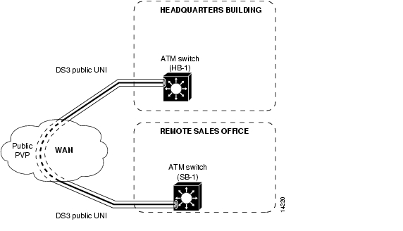
Figure 6-8 shows a public UNI interface over a DS3 connection between the ATM switch router (HB-1) in the Headquarters building and the ATM switch router (SB-1) in the Remote Sales building. To support signalling across this connection, a VP tunnel must be configured.
Figure 6-8 Public VP Tunnel Network Example
Configuring a VP Tunnel for a Single Service Category
The type of VP tunnel described in this section is configured as a VP of a single service category. Only virtual circuits (VCs) of that service category can transit the tunnel.
To configure a VP tunnel connection for a single service category, perform the following steps, beginning in global configuration mode:
Note
Examples
The following example shows how to configure the ATM VP tunnel on the ATM switch router (HB-1) at interface ATM 1/0/0, VPI 99:
Switch(HB-1)(config)# interface atm 1/0/0Switch(HB-1)(config-if)# atm pvp 99Switch(HB-1)(config-if)# exitSwitch(HB-1)(config)# interface atm 1/0/0.99Switch(HB-1)(config-subif)# endSwitch(HB-1)#The following example shows how to configure the ATM VP tunnel on the ATM switch router (SB-1) interface ATM 0/0/0, VPI 99:
Switch(SB-1)(config)# interface atm 0/0/0Switch(SB-1)(config-if)# atm pvp 99Switch(SB-1)(config-if)# exitSwitch(SB-1)(config)# interface atm 0/0/0.99Switch(SB-1)(config-subif)# endSwitch(SB-1)#Displaying the VP Tunnel Configuration
To show the ATM virtual interface configuration, use the following EXEC command:
show atm interface atm card/subcard/port.vpt#
Shows the ATM interface configuration.
The following example shows the ATM virtual interface configuration for interface ATM 1/0/0.99:
Switch# show atm interface atm 1/0/0.99IF Status: UP Admin Status: upAuto-config: enabled AutoCfgState: waiting for response from peerIF-Side: Network IF-type: UNIUni-type: Private Uni-version: V3.0<information deleted>Configuring a Shaped VP Tunnel
This section describes configuring a shaped VP tunnel for a single service category with rate-limited tunnel output on a switch.
A shaped VP tunnel is configured as a VP of the CBR service category. By default, this tunnel can carry VCs only of the CBR service category. However, you can configure this VP tunnel to carry VCs of other service categories. The overall output of this VP tunnel is rate-limited by hardware to the peak cell rate (PCR) of the tunnel.
Note
A shaped VP tunnel is defined as a CBR VP with a PCR. The following limitations apply:
•
•
•
•
•
•
•
•
•
Configuring a Shaped VP Tunnel on an Interface
To configure a shaped VP tunnel, perform the following steps, beginning in global configuration mode:
Note
Example
The following example shows how to configure a shaped VP tunnel with a VPI of 99 as ATM interface 0/0/0.99
Switch(config)# interface atm 0/0/0Switch(config-if)# atm pvp 99 shaped rx-cttr 100 tx-cttr 100Switch(config-if)# exitSwitch(config-if)# interface atm 0/0/0.99Switch(config-subif)#Displaying the Shaped VP Tunnel Configuration
To display the shaped VP tunnel interface configuration, use the following EXEC command:
show atm interface atm card/subcard/port.vpt#
Shows the ATM VP interface configuration.
For an example display from the show atm interface command, see the "Displaying the Hierarchical VP Tunnel Configuration" section .
Configuring a Hierarchical VP Tunnel for Multiple Service Categories
This section describes configuring a hierarchical VP tunnel for multiple service categories with rate-limited tunnel output.
A hierarchical VP tunnel allows VCs of multiple service categories to pass through the tunnel. In addition, the overall output of the VP tunnel is rate-limited to the PCR of the tunnel. There is no general limit on the number of connections allowed on a such a tunnel. Hierarchical VP tunnels can also support merged VCs for tag switching. See the "Configuring VC Merge" section .
Service categories supported include the following:
•
•
•
•
Note
While capable of carrying any traffic category, a hierarchical VP tunnel is itself defined as CBR with a PCR. The following limitations apply on the Catalyst 8540 MSR:
•
•
The following limitations apply on the Catalyst 8510 MSR and LightStream 1010:
•
•
The following limitations apply on the Catalyst 8540 MSR, Catalyst 8510 MSR and LightStream 1010:
•
•
•
–
–
–
•
•
•
Enabling Hierarchical Mode
Before configuring a hierarchical VP tunnel, you must first enable hierarchical mode, then reload the ATM switch router. Perform the following steps, beginning in global configuration mode:
Note
Example
The following example shows how to enable hierarchical mode, then save and reload the configuration.
Switch(config)# atm hierarchical-tunnelSwitch(config)# exitSwitch# copy system:running-config nvram:startup-configSwitch# reloadConfiguring a Hierarchical VP Tunnel on an Interface
To configure a hierarchical VP tunnel, perform the following steps, beginning in global configuration mode:
Note
Example
The following example shows how to configure a hierarchical VP tunnel with a PVP of 99 as ATM interface 0/0/0.99
Switch(config)# interface atm 0/0/0Switch(config-if)# atm pvp 99 hierarchical rx-cttr 100 tx-cttr 100Switch(config-if)# exitSwitch(config-if)# interface atm 0/0/0.99Switch(config-subif)#Displaying the Hierarchical VP Tunnel Configuration
To display the hierarchical VP tunnel interface configuration, use the following EXEC command:
show atm interface atm card/subcard/port.vpt#
Shows the ATM VP interface configuration.
Example
The following example shows the VP tunnel configuration on interface ATM 1/0/0 with PVP 99:
Switch# show atm interface atm 1/0/0.99Interface: ATM1/0/0.99 Port-type: vp tunnelIF Status: UP Admin Status: upAuto-config: enabled AutoCfgState: waiting for response from peerIF-Side: Network IF-type: UNIUni-type: Private Uni-version: V3.0Max-VPI-bits: 0 Max-VCI-bits: 14Max-VP: 0 Max-VC: 16383ConfMaxSvpcVpi: 0 CurrMaxSvpcVpi: 0ConfMaxSvccVpi: 0 CurrMaxSvccVpi: 0ConfMinSvccVci: 35 CurrMinSvccVci: 35Signalling: EnabledATM Address for Soft VC: 47.0091.8100.0000.0060.3e64.fe01.4000.0c81.9000.63Configured virtual links:PVCLs SoftVCLs SVCLs TVCLs Total-Cfgd Inst-Conns4 0 0 0 4 4Configuring an End-Point PVC to a PVP Tunnel
To configure an end point of a permanent virtual channel (PVC) to a previously created PVP tunnel, perform the following steps, beginning in global configuration mode:
The following restrictions apply to an end point of a PVC-to-PVP tunnel subinterface:
•
•
•
Example
The following example shows how to configure the example tunnel ATM 1/0/0.99 with a PVC from ATM interface 0/0/1 to the tunnel at ATM interface 1/0/0.99:
Switch(HB-1)(config)# interface atm 0/0/1Switch(HB-1)(config-if)# atm pvc 0 50 interface atm 1/0/0.99 99 40Displaying PVCs
To confirm PVC interface configuration, use the following EXEC command:
show atm vc interface atm card/subcard/port
Shows the ATM VC interface configuration.
Example
The following example shows the configuration of ATM subinterface 1/0/0.99 on the ATM switch router Switch(HB-1):
Switch(HB-1)# show atm vc interface atm 0/0/1Interface VPI VCI Type X-Interface X-VPI X-VCI Encap StatusATM0/0/1 0 5 PVC ATM2/0/0 0 41 QSAAL UPATM0/0/1 0 16 PVC ATM2/0/0 0 33 ILMI UPATM0/0/1 0 50 PVC ATM1/0/0.99 99 40 UPConfiguring Signalling VPCI for VP Tunnels
You can specify the value of the virtual path connection identifier (VPCI) that is to be carried in the signalling messages within a VP tunnel. The connection identifier information element (IE) is used in signalling messages to identify the corresponding user information flow. The connection identifier IE contains the VPCI and VCI.
Note
This feature can also be used to support connections over a virtual UNI.
To configure a VP tunnel connection signalling VPCI, perform the following steps, beginning in global configuration mode:
Example
The following example configures a VP tunnel on ATM interface 0/0/0, PVP 99, and then configures the connection ID VCPI as 0.
Switch(config)# interface atm 1/0/0Switch(config-if)# atm pvp 99Switch(config-if)# exitSwitch(config)# interface atm 1/0/0.99Switch(config-subif)# endDisplaying the VP Tunnel VPCI Configuration
To confirm the VP tunnel VPCI configuration, use the following privileged EXEC command:
Deleting VP Tunnels
To delete a VP tunnel connection, perform the following steps, beginning in global configuration mode:
Example
The following example shows deleting subinterface 99 at ATM interface 1/0/0 and then PVP half-leg 99:
Switch(HB-1)(config)# no interface atm 1/0/0.99Switch(HB-1)(config)# interface atm 1/0/0Switch(HB-1)(config-if)# no atm pvp 99Confirming VP Tunnel Deletion
To confirm the ATM virtual interface deletion, use the following EXEC command:
show atm interface [atm card/subcard/port[.vpt#]]
Shows the ATM interface configuration.
Example
The following example shows that ATM subinterface 1/0/0.99 on the ATM switch router (HB-1) has been deleted:
Switch(HB-1)# show interfaces atm 1/0/0IF Status: UP Admin Status: upAuto-config: disabled AutoCfgState: not applicableIF-Side: Network IF-type: NNIUni-type: not applicable Uni-version: not applicableMax-VPI-bits: 8 Max-VCI-bits: 14Max-VP: 255 Max-VC: 16383ConfMaxSvpcVpi: 255 CurrMaxSvpcVpi: 255ConfMaxSvccVpi: 255 CurrMaxSvccVpi: 255ConfMinSvccVci: 35 CurrMinSvccVci: 35Svc Upc Intent: pass Signalling: EnabledATM Address for Soft VC: 47.0091.8100.0000.00e0.4fac.b401.4000.0c80.8000.00Configured virtual links:PVCLs SoftVCLs SVCLs TVCLs PVPLs SoftVPLs SVPLs Total-Cfgd Inst-Conns4 0 0 0 0 0 0 4 3Logical ports(VP-tunnels): 0Input cells: 263843 Output cells: 2730105 minute input rate: 0 bits/sec, 0 cells/sec5 minute output rate: 0 bits/sec, 0 cells/secInput AAL5 pkts: 172265, Output AAL5 pkts: 176838, AAL5 crc errors: 0Configuring Interface and Connection Snooping
Snooping allows the cells from all connections, in either receive or transmit direction, on a selected physical port to be transparently mirrored to a snoop test port where an external ATM analyzer can be attached. Unlike shared medium LANs, an ATM system requires a separate port to allow nonintrusive traffic monitoring on a line.
Note
Snooping Test Ports (Catalyst 8510 MSR and LightStream 1010)
With the FC-PCQ installed, only the highest port on the last module in the ATM switch router can be configured as a snoop test port. Table 6-4 lists the interface number of the allowed snoop test port for the various port adapter types. If you specify an incorrect snoop test port for the currently installed port adapter type, an error appears on the console. The feature card per-class queuing (FC-PCQ) also does not support per-connection snooping.
The port number of the test port depends on the card type. Table 6-4 lists the allowed snoop test port number for the supported interfaces.
Table 6-4 Allowed ATM Snoop Ports with FC-PCQ
25-Mbps
4/1/111
OC-3
4/1/3
OC-12
4/1/0
DS3/E3
Not supported
CES
Not supported
1 Both transmit and receive interfaces must be on 25-Mbps port adapters.
Effect of Snooping on Monitored Port
There is no effect on cell transmission, interface or VC status and statistics, front panel indicators, or any other parameters associated with a port being monitored during snooping. Any port, other than the highest port, that contains a port adapter type with a bandwidth less than or equal to the port adapter bandwidth for the test port can be monitored by snooping.
Shutting Down Test Port for Snoop Mode Configuration
The port being configured as a test port must be shut down before configuration. While the test port is shut down and after snoop mode has been configured, no cells are transmitted from the test port until it is reenabled using the no shutdown command. A test port can be put into snoop mode even if there are existing connections to it; however, those connections remain "Down" even after the test port is reenabled using the no shutdown command. This includes any terminating connections for ILMI, PNNI, or signalling channels on the test port.
If you use a show atm interface command while the test port is enabled in snoop mode, the screen shows the following:
•
•
•
•
•
Other Configuration Options for Snoop Test Port
Most inapplicable configurations on the test port interface are disregarded while in snoop mode. However, the following configuration options are not valid when specified for the snoop test port and may affect the proper operation of the snoop mode on the test port:
•
•
•
•
•
Caution
Configuring Interface Snooping
The atm snoop interface atm command enables a snoop test port. Cells transmitted from the snoop test port are copies of cells from a single direction of a monitored port.
When in snoop mode, any prior permanent virtual connections to the snoop test port remain in the down state.
To configure interface port snooping, perform the following steps, beginning in global configuration mode:
Example
The following example shows how to configure ATM interface 12/1/3 as the port in snoop mode to monitor ATM interface 3/0/0, tested in the receive direction:
Switch(config)# interface atm 12/1/3Switch(config-if)# atm snoop interface atm 3/0/0 direction receiveDisplaying Interface Snooping
To display the test port information, use the following EXEC command:
Example
The following example shows the snoop configuration on the OC-3c port and the actual register values for the highest interface:
Switch# show atm snoopSnoop Test Port Name: ATM12/1/3 (interface status=SNOOPING)Snoop option: (configured=enabled) (actual=enabled)Monitored Port Name: (configured=ATM3/0/0) (actual=ATM3/0/0)Snoop direction: (configured=receive) (actual=receive)Configuring Per-Connection Snooping
With per-connection snooping you must specify both the snooped connection endpoint and the snooping connection endpoint. The Cisco IOS software adds the snooping connection endpoint as a leaf to the snooped connection. The root of the temporary multicast connection depends on the direction being snooped. Snooping in the direction of leaf to root is not allowed for multicast connections. Per-connection snooping features are as follows:
•
•
The snooping connection can be configured on any port when there is no VPI/VCI collision for the snoop connection with the existing connections on the port. Also the port should have enough resources to satisfy the snoop connection resource requirements. In case of failure, due to VPI/VCI collision or resource exhaustion, a warning message is displayed, and you can reconfigure the connection on a different port.
To snoop both transmit and receive directions of a connection, you need to configure two different snoop connections.
Note
Nondisruptive per-connection snooping is achieved by dynamically adding a leaf to an existing connection (either unicast or multicast). This can lead to cell discard if the added leaf cannot process the snooped cells fast enough. For a multicast connection, the queue buildup is dictated by the slowest leaf in the connection. The leaf added for snooping inherits the same traffic characteristics as the other connection leg. This ensures that the added leaf does not become the bottleneck and affect the existing connection.
To configure connection snooping, perform the following steps, beginning in global configuration mode:
Examples
The following example shows how to configure VC 100 200 on ATM interface 3/1/0 to snoop VC 200 150 on ATM interface 1/0/0:
Switch(config)# interface atm 3/1/0Switch(config-if)# atm snoop-vc 100 200 interface atm 1/0/0 200 150 direction receiveThe following example shows how to configure VP 100 on ATM interface 3/1/0 to snoop VP 200 on ATM interface 1/0/0:
Switch(config)# interface atm 3/1/0Switch(config-if)# atm snoop-vp 100 interface atm 1/0/0 200 direction receiveDisplaying Per-connection Snooping
To display the test per-connection information, use the following EXEC commands:
Examples
The following example shows all VC snoop connections on the ATM switch router:
Switch> show atm snoop-vcSnooping SnoopedInterface VPI VCI Type X-Interface X-VPI X-VCI Dir StatusATM0/0/2 0 5 PVC ATM0/1/1 0 5 Rx DOWNATM0/0/2 0 16 PVC ATM0/1/1 0 16 Rx DOWNATM0/1/2 0 5 PVC ATM0/0/1 0 5 Tx DOWNATM0/1/2 0 16 PVC ATM0/0/1 0 16 Tx DOWNATM0/1/2 0 18 PVC ATM0/0/1 0 18 Tx UPATM0/1/2 0 100 PVC ATM0/0/1 0 100 Tx DOWNATM0/1/2 0 201 PVC ATM0/0/1 0 201 Tx DOWNATM0/1/2 0 202 PVC ATM0/0/1 0 202 Tx DOWNATM0/1/2 0 300 PVC ATM0/0/1 0 300 Tx DOWNATM0/1/2 0 301 PVC ATM0/0/1 0 301 Tx DOWNThe following example shows the VC snoop connections on ATM interface 0/1/2:
Switch> show atm snoop-vc interface atm 0/1/2Snooping SnoopedInterface VPI VCI Type X-Interface X-VPI X-VCI Dir StatusATM0/1/2 0 5 PVC ATM0/0/1 0 5 Tx DOWNATM0/1/2 0 16 PVC ATM0/0/1 0 16 Tx DOWNATM0/1/2 0 18 PVC ATM0/0/1 0 18 Tx UPATM0/1/2 0 100 PVC ATM0/0/1 0 100 Tx DOWNATM0/1/2 0 201 PVC ATM0/0/1 0 201 Tx DOWNATM0/1/2 0 202 PVC ATM0/0/1 0 202 Tx DOWNATM0/1/2 0 300 PVC ATM0/0/1 0 300 Tx DOWNATM0/1/2 0 301 PVC ATM0/0/1 0 301 Tx DOWNThe following example shows the VC snoop connection 0, 55 on ATM interface 0/0/2 in extended mode with the switch processor feature card installed:
Switch> show atm snoop-vc interface atm 0/0/2 0 55Interface: ATM0/0/2, Type: oc3suniVPI = 0 VCI = 55Status: DOWNTime-since-last-status-change: 00:01:59Connection-type: PVCCast-type: snooping-leafPacket-discard-option: disabledUsage-Parameter-Control (UPC): passWrr weight: 32Number of OAM-configured connections: 0OAM-configuration: disabledOAM-states: Not-applicableCross-connect-interface: ATM0/1/1, Type: oc3suniCross-connect-VPI = 0Cross-connect-VCI = 5Cross-connect-UPC: passCross-connect OAM-configuration: disabledCross-connect OAM-state: Not-applicableThreshold Group: 6, Cells queued: 0Rx cells: 0, Tx cells: 0Tx Clp0:0, Tx Clp1: 0Rx Clp0:0, Rx Clp1: 0Rx Upc Violations:0, Rx cell drops:0Rx Clp0 q full drops:0, Rx Clp1 qthresh drops:0Rx connection-traffic-table-index: 3Rx service-category: VBR-RT (Realtime Variable Bit Rate)Rx pcr-clp01: 424Rx scr-clp01: 424Rx mcr-clp01: noneRx cdvt: 1024 (from default for interface)Rx mbs: noneTx connection-traffic-table-index: 3Tx service-category: VBR-RT (Realtime Variable Bit Rate)Tx pcr-clp01: 424Tx scr-clp01: 424Tx mcr-clp01: noneTx cdvt: noneTx mbs: noneThe following example shows all VP snoop connections on the ATM switch router:
Switch> show atm snoop-vpSnooping SnoopedInterface VPI Type X-Interface X-VPI Dir StatusATM0/1/2 57 PVP ATM0/0/1 57 Tx DOWNThe following example shows all VP snoop connections on ATM interface 0/1/2, VPI = 57, in extended mode with the switch processor feature card installed:
Switch> show atm snoop-vp interface atm 0/1/2 57Interface: ATM0/1/2, Type: oc3suniVPI = 57Status: DOWNTime-since-last-status-change: 00:14:46Connection-type: PVPCast-type: snooping-leafUsage-Parameter-Control (UPC): passWrr weight: 32Number of OAM-configured connections: 0OAM-configuration: disabledOAM-states: Not-applicableCross-connect-interface: ATM0/0/2, Type: oc3suniCross-connect-VPI = 57Cross-connect-UPC: passCross-connect OAM-configuration: disabledCross-connect OAM-state: Not-applicableThreshold Group: 5, Cells queued: 0Rx cells: 0, Tx cells: 0Tx Clp0:0, Tx Clp1: 0Rx Clp0:0, Rx Clp1: 0Rx Upc Violations:0, Rx cell drops:0Rx Clp0 q full drops:0, Rx Clp1 qthresh drops:0Rx connection-traffic-table-index: 1Rx service-category: UBR (Unspecified Bit Rate)Rx pcr-clp01: 7113539Rx scr-clp01: noneRx mcr-clp01: noneRx cdvt: 1024 (from default for interface)Rx mbs: noneTx connection-traffic-table-index: 1Tx service-category: UBR (Unspecified Bit Rate)Tx pcr-clp01: 7113539Tx scr-clp01: noneTx mcr-clp01: noneTx cdvt: noneTx mbs: none
![]()
![]()
![]()
![]()
![]()
![]()
![]()
![]()
Posted: Mon Oct 11 09:56:26 PDT 2004
All contents are Copyright © 1992--2004 Cisco Systems, Inc. All rights reserved.
Important Notices and Privacy Statement.