|
|

Table Of Contents
Configuring Classical IP over ATM
Configuring Classical IP over ATM in an SVC Environment
Configuring Classical IP over ATM in a PVC Environment
Mapping a Protocol Address to a PVC Using Static Map Lists
Configuring a PVC-Based Map List
Configuring an SVC-Based Map List
Configuring IP over ATM
This chapter describes how to configure IP over ATM on the ATM switch router. The primary use of IP over ATM is for inband management of the ATM switch router.
Note
This chapter provides advanced configuration instructions for the Catalyst 8540 MSR, Catalyst 8510 MSR, and LightStream 1010 ATM switch routers. For further information about Layer 3 protocols over ATM, refer to the Guide to ATM Technology. For complete descriptions of the commands mentioned in this chapter, refer to the ATM Switch Router Command Reference publication.
This chapter includes the following sections:
•
•
Configuring Classical IP over ATM
This section describes configuring a port on a ATM switch router to allow a classical IP-over-ATM connection to the ATM switch router's route processor and optional ATM router module.
The following sections describe configuring the ATM switch router for classical IP over ATM in either a switched virtual channel (SVC) or permanent virtual channel (PVC) environment.
Configuring Classical IP over ATM in an SVC Environment
This section describes classical IP over ATM in an SVC environment. It requires configuring only the device's own ATM address and that of a single ATM Address Resolution Protocol (ARP) server into each client device.
For a detailed description of the role and operation of the ATM ARP server, refer to the Guide to ATM Technology.
The ATM switch router can be configured as an ATM ARP client to work with any ATM ARP server conforming to RFC 1577. Alternatively, one of the ATM switch routers in a logical IP subnet (LIS) can be configured to act as the ATM ARP server itself. In that case, it automatically acts as a client as well. The following sections describe configuring the ATM switch router in an SVC environment as either an ATM ARP client or an ATM ARP server.
Configuring as an ATM ARP Client
In an SVC environment, configure the ATM ARP mechanism on the interface by performing the following steps, beginning in global configuration mode:
Step 1
Switch(config)# interface atm 0
Switch(config-if)#
Selects the interface to be configured.
Step 2
Switch(config-if)# atm nsap-address nsap-address
or
Switch(config-if)# atm esi-address esi.selector
Specifies the network service access point (NSAP) ATM address of the interface.
or
Specifies the end-system-identifier (ESI) address of the interface.
Step 3
Switch(config-if)# ip address ip-address mask
Specifies the IP address of the interface.
Step 4
Switch(config-if)# atm arp-server nsap nsap-address
Specifies the ATM address of the ATM ARP server.
Step 5
Switch(config-if)# exit
Switch(config)#
Exits interface configuration mode.
Step 6
Switch(config)# atm route addr-prefix1 atm 0 internal
Configures a static route through the ATM switch router to the route processor interface. See the following note.
1 Address prefix is first 19 bytes of the NSAP address.
Note
Note
NSAP Address Example
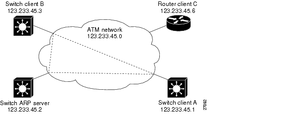
Figure 12-1 shows three ATM switch routers and a router connected using classical IP over ATM.
Figure 12-1 Classical IP over ATM Connection Setup
The following example shows how to configure the route processor interface ATM 0 of client A in Figure 12-1, using the NSAP address:
Client A(config)# interface atm 0Client A(config-if)# atm nsap-address 47.0091.8100.0000.1111.1111.1111.1111.1111.1111.00Client A(config-if)# ip address 123.233.45.1 255.255.255.0Client A(config-if)# atm arp-server nsap 47.0091.8100.0000.1111.1111.1111.2222.2222.2222.00Client A(config-if)# exitClient A(config)# atm route 47.0091.8100.0000.1111.1111.1111.1111.1111.1111 atm 0 internalESI Example
The following example shows how to configure route processor interface ATM 0 of client A in Figure 12-1 using the ESI:
Client A(config)# interface atm 0Client A(config-if)# atm esi-address 0041.0b0a.1081.40Client A(config-if)# ip address 123.233.45.1 255.255.255.0Client A(config-if)# atm arp-server nsap 47.0091.8100.0000.1111.1111.1111.2222.2222.2222.00Client A(config-if)# exitClient A(config)#Configuring as an ATM ARP Server
Cisco's implementation of the ATM ARP server supports a single, nonredundant server per LIS and one ATM ARP server per subinterface. Thus, a single ATM switch router can support multiple ARP servers by using multiple interfaces.
To configure the ATM ARP server, perform the following steps, beginning in global configuration mode:
Step 1
Switch(config)# interface atm 0[.subinterface#]
Switch(config-if)#
Selects the interface to be configured.
Step 2
Switch(config-if)# atm nsap-address nsap-address
or
Switch(config-if)# atm esi-address esi.selector
Specifies the NSAP ATM address of the interface.
or
Specifies the end-system-identifier address of the interface.
Step 3
Switch(config-if)# ip address ip-address mask
Specifies the IP address of the interface.
Step 4
Switch(config-if)# atm arp-server time-out minutes1
Configures the ATM ARP server optional idle timer.
Step 5
Switch(config-if)# atm route addr-prefix2 atm 0 internal
Configures a static route through the ATM switch router to the route processor interface. See the following note.
1 This form of the atm arp-server command indicates that this interface performs the ATM ARP server functions. When you configure the ATM ARP client (described earlier), the atm arp-server command is used—with a different keyword and argument—to identify a different ATM ARP server to the client.
2 Address prefix is first 19 bytes of the NSAP address.
Note
The idle timer interval is the number of minutes a destination entry listed in the ATM ARP server's ARP table can be idle before the server takes any action to timeout the entry.
Example
The following example configures the route processor interface ATM 0 as an ARP server (shown in Figure 12-1):
ARP_Server(config)# interface atm 0ARP_Server(config-if)# atm esi-address 0041.0b0a.1081.00ARP_Server(config-if)# atm arp-server selfARP_Server(config-if)# ip address 123.233.45.2 255.255.255.0Displaying the IP-over-ATM Interface Configuration
To show the IP-over-ATM interface configuration, use the following EXEC commands:
show atm arp-server
Shows the ATM interface ARP configuration.
show atm map
Shows the ATM map list configuration.
Examples
In the following example, the show atm arp-server command displays the configuration of the interface ATM 0:
Switch# show atm arp-serverNote that a '*' next to an IP address indicates an active callIP Address TTL ATM AddressATM2/0/0:* 10.0.0.5 19:21 4700918100567000000000112200410b0a108140The following example displays the map-list configuration of the static map and IP-over-ATM interfaces:
Switch# show atm mapMap list ATM2/0/0_ATM_ARP : DYNAMICarp maps to NSAP 36.0091810000000003D5607900.0003D5607900.00, connection up, VPI=0 VCI=73, ATM2/0/0ip 5.1.1.98 maps to s 36.0091810000000003D5607900.0003D5607900.00, broadcast, connection up, VPI=0 VCI=77, ATM2/0/0Map list ip : PERMANENTip 5.1.1.99 maps to VPI=0 VCI=200Configuring Classical IP over ATM in a PVC Environment
This section describes how you configure classical IP over ATM in a permanent virtual channel (PVC) environment. The ATM Inverse ARP (InARP) mechanism is applicable to networks that use PVCs, where connections are established but the network addresses of the remote ends are not known. A server function is not used in this mode of operation.
In a PVC environment, configure the ATM InARP mechanism by performing the following steps, beginning in global configuration mode:
Repeat these tasks for each PVC you want to create.
The inarp minutes interval specifies how often Inverse ARP datagrams are sent on this virtual circuit. The default value is 15 minutes.
Note
Example
The following example shows how to configure an IP-over-ATM interface on interface ATM 0, using a PVC with AAL5SNAP encapsulation, inverse ARP set to ten minutes, VPI = 0, and VCI = 100:
Switch(config)# interface atm 0Switch(config-if)# ip address 11.11.11.11 255.255.255.0Switch(config-if)# atm pvc 0 100 interface atm 0/0/0 50 100 encap aal5snap inarp 10Displaying the IP-over-ATM Interface Configuration
To show the IP-over-ATM interface configuration, use the following EXEC command:
Example
The following example displays the map-list configuration of the static map and IP-over-ATM interfaces:
Switch# show atm mapMap list yyy : PERMANENTip 1.1.1.2 maps to VPI=0 VCI=200Map list zzz : PERMANENTMap list a : PERMANENTMap list 1 : PERMANENTMap list ATM2/0/0_ATM_ARP : DYNAMICarp maps to NSAP 47.009181005670000000001122.00410B0A1081.40, connection up, VPI=0 VCI=85, ATM2/0/0ip 10.0.0.5 maps to NSAP 47.009181005670000000001122.00410B0A1081.40, broadcast, ATM2/0/0Mapping a Protocol Address to a PVC Using Static Map Lists
The ATM interface supports a static mapping scheme that identifies the ATM address of remote hosts or ATM switch routers. This IP address is specified as a permanent virtual channel (PVC) or as a network service access point (NSAP) address for switch virtual channel (SVC) operation.
The following sections describe configuring both PVC-based and SVC-based map lists on the ATM switch router. For a more detailed discussion of static map lists, refer to the Guide to ATM Technology.
Configurations for both PVC and SVC map lists are described in the following sections:
•
•
Configuring a PVC-Based Map List
This section describes how to map a PVC to an address, which is a required task if you are configuring a PVC.
You enter mapping commands as groups. You first create a map list and then associate it with an interface. Perform the following steps, beginning in global configuration mode:
You can create multiple map lists, but only one map list can be associated with an interface. Different map lists can be associated with different interfaces.
Example
Figure 12-2 illustrates a connection configured with a PVC map list.
Figure 12-2 PVC Map List Configuration Example
The following example shows the commands used to configure the connection in Figure 12-2.
Switch(config)# interface atm 0Switch(config-if)# ip address 1.1.1.1 255.0.0.0Switch(config-if)# map-group yyySwitch(config-if)# atm pvc 0 200 interface atm 3/0/0 100 300 encap aal5snapSwitch(config-if)# exitSwitch(config)# ip route 1.1.1.1 255.0.0.0 1.1.1.2Switch(config)# map-list yyySwitch(config-map-list)# ip 1.1.1.2 atm-vc 200Displaying the Map-List Interface Configuration
To show the map-list interface configuration, use the following EXEC command:
Example
The following example displays the map-list configuration at interface ATM 0:
Switch# show atm mapMap list yyy : PERMANENTip 1.1.1.2 maps to VPI=0 VCI=200Configuring an SVC-Based Map List
This section describes how to map an SVC to an NSAP address. This is a required task if you are configuring an SVC.
You enter mapping commands as groups. You first create a map list and then associate it with an interface. Perform the following steps, beginning in global configuration mode:
You can create multiple map lists, but only one map list can be associated with an interface. Different map lists can be associated with different interfaces.
Examples
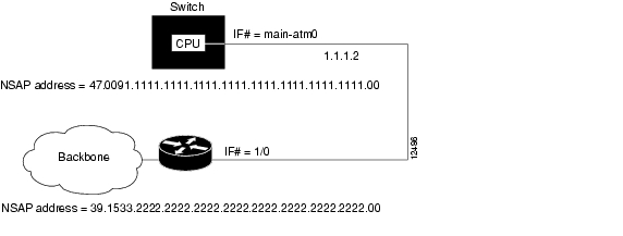
Figure 12-3 illustrates an SVC connection configured with a map list.
Figure 12-3 SVC Map-List Configuration Example
The following example shows the commands used to configure the connection in Figure 12-3:
Switch(config)# interface atm 0Switch(config-if)# ip address 1.1.1.1 255.0.0.0Switch(config-if)# atm nsap-address 47.0091.1111.1111.1111.1111.1111.1111.1111.1111.00Switch(config-if)# map-group zzzSwitch(config-if)# exitSwitch(config)# map-list zzzSwitch(config-map-list)# ip 1.1.1.2 atm-nsap 39.1533.2222.2222.2222.2222.2222.2222.2222.2222.00Displaying the Map-List Interface Configuration
To show the map-list interface configuration, use the following EXEC command:
Example
The following example displays the map-list configuration at interface ATM 0:
Switch# show atm mapMap list zzz : PERMANENTip 1.1.1.2 maps to NSAP AC.153322222222222222222222.222222222222.00
![]()
![]()
![]()
![]()
![]()
![]()
![]()
![]()
Posted: Mon Oct 11 09:09:18 PDT 2004
All contents are Copyright © 1992--2004 Cisco Systems, Inc. All rights reserved.
Important Notices and Privacy Statement.