|
|

This chapter describes the installation and operation of the Cisco Access Server 5100 AC and DC power supplies.
In addition to installation guidelines, this chapter contains the following important information:
When the Access Server 5100 system is shipped unassembled, protective safety panels cover all the chassis slots. Leave these panels in place on any unoccupied slots.
 | Warning Do not block the openings on the top and bottom of the chassis. When installing more than one chassis in an equip-ment rack, leave room above and below each chassis for adequate venti-lation. Installing fan trays in the rack along with the chassis can help regulate the temper-ature. |
The optimal rack installation is as follows:
In a standard 19-inch equipment rack, the brackets that come with the chassis are not required. Use the screws that came with the equipment to mount the chassis. You will need two screws for each of the mounting rails.
Perform the following steps to install the Access Server 5100 chassis in a 19-inch rack:
Step 1 Slide the chassis into the rack.
Step 2 Beginning with the two bottom screws, secure all four of the chassis mounting flange slots to the front vertical rails of the rack.
The chassis can be mounted in a 23-inch rack by using the provided brackets as extenders.
Perform the following steps to install the Access Server 5100 chassis in a 23-inch rack:
Step 1 In a standard 23-inch rack, use the extender brackets to bolt the chassis mounting flange slots to the equipment rack, keeping the front of the chassis flush with the front of the rack.
In a shallow 23-inch rack (or frame-type rack) use the extender brackets to bolt the front of the chassis extending out five inches in front of the rack.
Step 2 Bolt the extender brackets to the front of the chassis in the desired configuration.
Step 3 Bolt the extender and chassis to the equipment rack, beginning with the lower bolts on both sides.
Figure 3-1 shows how to install the chassis in the two different types of racks.

If the rack does not have forced air or built-in cooling to help maintain temperature at 25°C, fan trays must be installed in the rack to provide ventila-tion and control the temperature.
Fan trays should be installed in a rack according to the minimum configuration of one fan tray between every two chassis, and one fan tray at the top. (See Figure 3-2.) Three inches of air space must be left below each fan tray to ensure adequate air circulation and cooling.
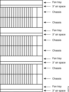
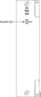
Figure 3-3 shows the Access Server 5100 AC power supply. A DC power supply option is available but is not shown.
 | Warning There may be induced voltage between the fully installed chassis and the equipment at the other end of the EIA/TIA-232 inter-face. To avoid any potential shock hazard, do not touch both pieces of equipment at the same time. |
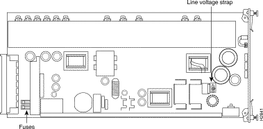
Power supplies are available in both AC and DC versions. Verify that you have received the correct version by checking the silkscreen label on the front panel of the power supply. Also, notice that the DC power supply does not have a line voltage strap (see Figure 3-4).
The AC power supply enables AC power to the system and provides DC power to the card slots of the chassis. The DC version enables the chassis to accept a -48 VDC power input to the system, and converts DC voltages to power the card slots. Both power supplies are required in an Access Server 5100 chassis.
The AC power supply is shipped with signal and chassis grounds separated. The DC power supply also separates the -48 VDC input power ground. If your installation requires that you connect these grounds so that they are shorted together, contact your customer service representative.
AC power input may be from either of the following sources.
The power supply is shipped with AC line voltage set for 120 VAC. To set the supply to use 240 VAC, follow these steps:
Step 1 Locate the line voltage strap shown in Figure 3-4 and the 120/240 label that is printed on the power supply printed circuit board. The strap's plastic casing holds a heavy-duty wire shunt that connects the lower two of the strap's three contacts in the 120 VAC position (see Figure 3-4).
Step 2 Lift up the shunt casing. If necessary, use a screwdriver for leverage.
Step 3 Replace the shunt so that it connects the top two contacts. This is the 240 VAC position.
Perform the following steps to install the power supplies:
Step 1 Verify that you are installing the correct type of power supply; that is, a DC power supply for a DC chassis or an AC power supply for an AC chassis (the AC chassis can be easily identified by the power rating information screened on rear panel of the power supply.
Step 2 For AC power supplies, reset the line voltage strap if necessary, as described in the previous section.
Step 3 The power supply slots are the two slots on the far right side of the chassis. Unscrew and remove one of the two safety panels from a power supply slot, or two safety panels if you're installing two power supplies. Set the panels and screws aside.
Step 4 With the DIN connector toward the bottom of the power supply and the power supply components to your left, insert the power supply into the upper and lower card guides of the slot. As you slide the power supply in, lift the ejector tab at the top right of the power supply front panel to allow the unit to enter. Slide the unit in smoothly and ensure that its DIN connector is firmly seated in the connector in the power supply backplane.
Step 5 Tighten the captive screws on the front panel to secure the unit(s). Underwriters' Laboratory (UL) requires that the power supplies be screwed in place.
 | Warning The capacitors on the power supply require ten seconds to dis-charge when the card is unplugged. Do not touch the board during that period. When removing a power supply, pull it out halfway and wait ten seconds. After ten seconds, the supply can safely be removed. Be careful, however, in handling it: some components, in particular the heat sinks, may be very hot. |
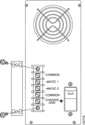
To provide power to the DC chassis, you must connect your DC power source to the terminals at the rear of the chassis. As shown in Figure 3-5, the five terminal lugs are shielded with a plastic cover, which is held in place by two screws.
Perform the following steps to cable the DC chassis:
Step 1 First, check to be sure that you have a DC chassis with the terminal block shown in Figure 3-5. Placing a DC power supply into an AC chassis may blow a fuse, and will not provide power to the system.
Step 2 Check that the power switch is in the OFF position (the switch is toggled toward the "0").
Step 3 Remove the plastic cover to expose the terminals. One terminal is labeled CHASSIS GND (ground), two are labeled COMMON, and there are two -48 VDC terminals. Each ter-minal will accept spade or ring lugs, or direct con-nection with 12 to 16 gage wire. To make a connec-tion, loosen the terminal screw, insert an exposed wire or terminal lug, and retighten the screw.
Step 4 You may optionally wire the chassis ground terminal to an earth source.
Step 5 The two common terminals are internally tied within the chassis. Connect the ground (common) wire from your -48 VDC source to either of the two common terminals.
Step 6 A shorting bar connects the two -48 VDC terminals (-48 VDC 1 and -48 VDC 2). If you are using a single input power source (that is, 2 wires), leave the shorting bar in place. This assures that power will be supplied to both power supply slots. Connect the -48 VDC source wire to either of the -48 VDC terminals.
Step 7 Be sure that all terminal screws are tightened; then replace the plastic cover over the terminal block and screw it down.
Perform the following procedure to power on the system:
Step 1 For the AC chassis, plug the AC cord into the connector on the power supply, and then into the AC power supply source. The connector and power switch are at the rear of the chassis, behind the power supplies. See Figure 3-6.
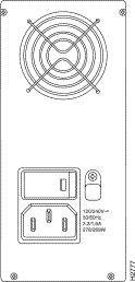
 | Caution The power supplies are not auto-sensing for AC input voltage. Be sure the 120/240V strap on each power supply is set correctly before powering on the system. |
Step 2 Turn ON the power switch (from zero [0] to one [1]).
Step 3 Check the LED on the power supply front panel. A green LED for each installed power supply indicates proper operation. If the LED is solid red, there has been a failure. See "Power Failure Diagnostics" later in this chapter.
Check the front panel LED to see if the power supply is installed correctly. If the LED does not go on, the power supply has failed, and you should contact your customer service representative.
Refer to the appropriate chapter for installation instructions for the feature cards:
Each Access Server 5100 installation will vary to some extent. We supply certain cables that are required for connecting components of the chassis. We expect that network managers will fill the additional cabling needs of their installations. See the "Cable and Port Specifications" appendix for pinout information for interface ports and cables.
This section provides information to help diagnose power problems you may encounter on initial power-up.
Failure of a power supply may be caused by any of the following conditions:
The power supplies are fully short-circuit protected. If a current overload is sensed at the power supply output terminals, the power supply auto-matically shuts down until the fault is corrected.
If overvoltage is sensed at the output terminals, the power supply immediately shuts down. In this case, remove the power supply and plug it in again to recycle the power.
The run/fail LED is located on the front of the power supply, as shown in Figure 3-3. If a power supply run/fail LED is red, try the brief sequence of tests described in the next section, "Power Supply Overvoltage or Fuse Problem." Depending on the situation, these procedures should enable you to diagnose the cause of the problem.
 | Warning The capacitors on the power supply require ten seconds to dis-charge when the card is unplugged. Do not touch the printed circuit card during that time. When removing a power supply, pull it out halfway and wait 10 seconds. After ten seconds, the power supply can safely be removed. Be careful, however, in handling it: some components, in particular the heat sinks, may be very hot. |
Perform the following steps if you suspect a power supply over-voltage or fuse problem:
Step 1 Observe the warning about not touching hot compo-nents. Halfway unplug the power supply whose run/fail LED is flashing and wait at least ten seconds. Plug the power supply in again and check the run/fail LED on the front panel.
The problem may have been minor, and the unit may reset. If not, continue with Step 2.
Step 2 Completely remove the faulty power supply. Check the fuse(s), shown in Figure 3-4.
Step 3 Replace the blown fuse, if necessary. The AC fuses are 5 x 20, 6.3A, 250V; the DC fuse is a Littlefuse #314012, Type #AB Fast Action Fuse, 12A, 250V. Fuses should be available at a local electronic distributor. If you cannot find them, contact your customer service representative.
Step 4 Plug the power supply in again.
Step 5 If the fuses are not at fault, proceed to the next section, "Overload Conditions."
If you suspect an overload condition, check for a network interface card (NIC) failure. Remove each NIC, one at a time, until the power supply indicator goes on. The last NIC removed is probably faulty.
![]()
![]()
![]()
![]()
![]()
![]()
![]()
![]()
Posted: Tue Oct 1 03:59:00 PDT 2002
All contents are Copyright © 1992--2002 Cisco Systems, Inc. All rights reserved.
Important Notices and Privacy Statement.