| United States-English |
|
|
|
HP-UX System Administrator's Guide: Overview: HP-UX 11i Version 3 > Chapter 3 Major Components of HP-UXStorage on HP-UX |
|
Of all the resources managed by any operating system, arguably the most important is storage. Storage is a generic term referring to devices that store data. Storage can take many forms, including:
In the HP-UX operating system, storage can be used in many ways; among them:
Like networking and many other subsystems in the computing world, storage is comprised of many layers, from the physical devices to the applications that read and write data to those devices. Collectively these layers are known as the storage stack. The following sections cover the various components of the HP-UX storage stack. At the lowest level of the storage stack are the physical devices that store and retrieve data. Usually these are disk drives, but they can be other storage devices as well, including:
Individual disk drives (whether standalone or in an array or enclosure) are often referred to as LUNs. The term “LUN” stands for “Logical Unit”, and while it is often associated with a physical disk drive (drive unit) within a larger array device, LUNs can point to other (logically defined) subsets of a larger device. Physical disk drives can be used in a standalone mode; that is, they can be partitioned, formatted with a file system, used for paging, or used by database applications as units of storage. However, physical disk drives are usually grouped into larger pools of space that can then be divided into logical storage containers. These containers (called volumes or logical volumes, depending on which volume manager you are using) are not required to respect the boundaries of the physical drives in the group. That is, they can span multiple physical devices. Volume managers enable you to divide and allocate these pools of space into logical storage containers. The pools of space are called volume groups in the Logical Volume Manager (LVM) and disk groups in the VERITAS Volume Manager (VxVM). The logical storage containers are referred to as logical volumes in LVM or simply volumes in VxVM. To applications, file systems, and databases, these volumes appear to be physical disks and are treated as such. HP-UX 11i version 3 supports the following volume managers:
Both volume managers can co-exist on a server. Each volume manager keeps track of which disks it is controlling and any given physical disk can only be a controlled by one volume manager at a time. The utility vxvmconvert can convert an LVM physical volume to a VxVM disk if you want to migrate a disk from LVM to VxVM for greater configuration flexibility. With HP-UX 11i version 3, there are two volume managers to choose from:
You can use both simultaneously (on different physical disks), but usually you will choose one or the other and use it exclusively. Table 3-1 provides a comparison of the two volume managers to help you determine which will best suit your needs. Table 3-1 Volume Manager Feature and Terminology Comparison
When using a volume manager, the first step is to group physical drives into pools of disk space called:
Once you have grouped physical disk drives into disk/volume groups, the collective space can be divided into logical storage containers that can be smaller or larger than any individual drive in the group. These logical storage containers are called:
Once defined, individual volumes or logical volumes can be used for:
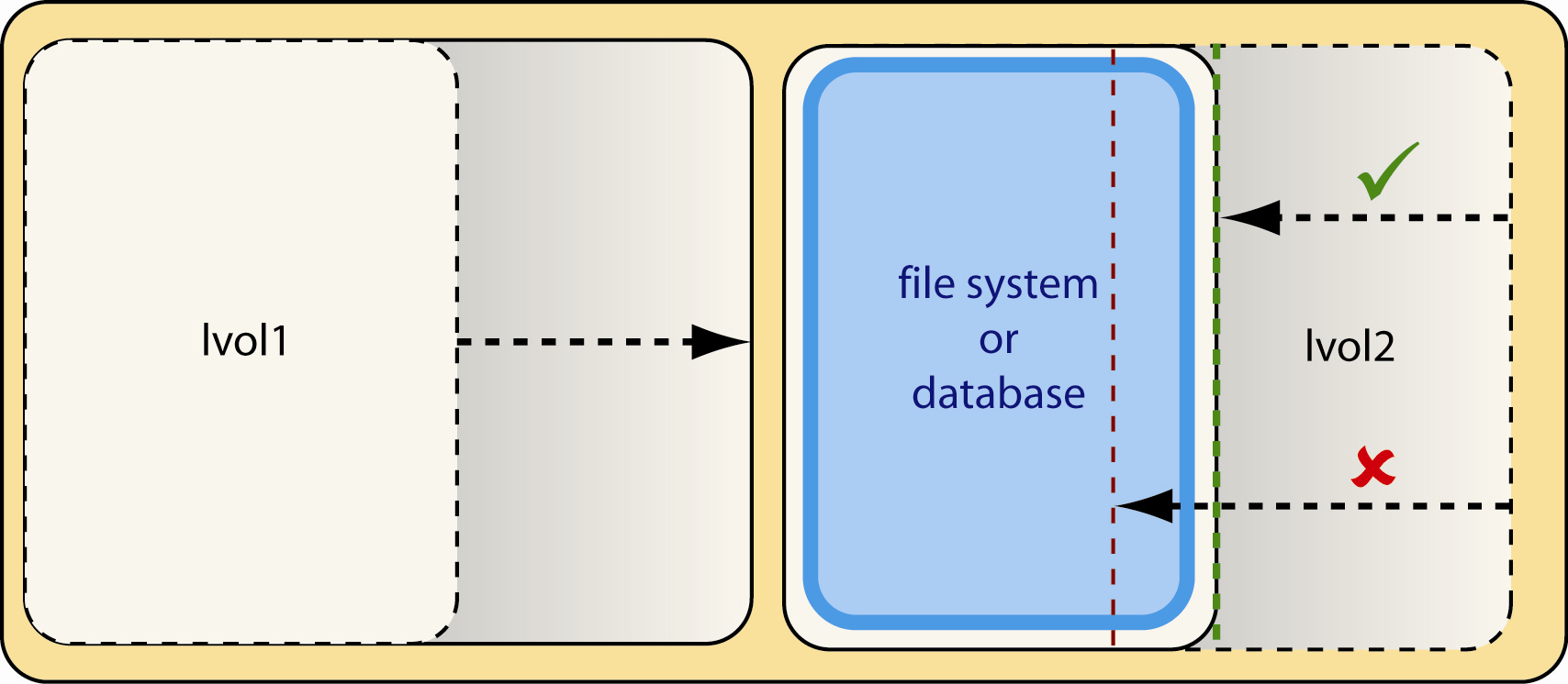
Logical volumes can be made larger or smaller as needed (if the data they contain support these operations). If you are not using a volume (or physical disk) for swap space or raw disk access (for example disk space managed by a database application), you are probably using it for file storage. The directories, files, and file data are usually distributed throughout a volume or disk drive. In the same way a card catalog allows you to locate a specific book in a large library, the primary function of a file system is to maintain the pointers to the files stored in a volume or on a physical disk so that those files can be later retrieved. These are not merely pointers indicating which file is in which directory; these are the low level pointers and other vital information, for example:
File systems also have other important functions, for example maintaining ownership and access privilege information so that HP-UX security functions can ensure that only those authorized to access a file or directory can do so. As with volume managers, HP-UX offers you several choices of file system types to choose from. Specifically: In addition to the previous file system types, HP-UX 11i version 3 supports:
If your operations depend on high performance disk I/O, in addition to ensuring that you are using high-speed interfaces (for example, Fibre Channel), consider the following: Disk striping spreads data over multiple physical devices in such a way that successive writes occur on different devices. In this way, the second chunk of data to be written does not have to wait for the device writing the first chunk to finish. In essence, if you have n devices striped together, then you can write n chunks of data simultaneously (or nearly simultaneously) without having to wait for devices to become ready for subsequent data. Striping can be performed at the device level if you are using a disk array, RAID array, or other hardware that supports RAID operations. Other types of disks striping can be performed by LVM or the VERITAS Volume Manager (VxVM). For information about performing striping using one of the volume managers, see lvcreate(1M) or vxassist(1M). You can specify the size of data chunks to use with striping. Hardware data striping is accomplished by using certain RAID configurations. Striping related RAID levels commonly used on HP disk arrays that support RAID are:
For the same reasons as described in Disk Striping, the more you can balance disk access, the better performance you will achieve from disk reads and writes. This reduces the chance that a given device will be busy servicing another data access operation, causing additional reads and writes to wait. Your choice of file system type can also affect the efficiency of accessing your data. The VERITAS File System (VxFS) is generally faster than using the HFS file system. Beginning with HP-UX 11i version 3, HP-UX 11i supports device multipathing, a new technology that associates device files with devices by using unique device IDs rather than the hardware path to the devices. This means that a single device file can represent multiple hardware paths to a given device which, when combined with hardware that has multiple ports (supporting multiple physical connections), yields not only redundant paths to the device, but greater I/O bandwidth. HP-UX 11i version 3 can automatically load balance between multiple physical connections to a device, improving I/O efficiency. For more information on device multipathing, see “How Storage is Addressed”. Though the topic of disk mirroring is more of a data redundancy topic, there are performance reasons for mirroring. If you use a RAID 1 (mirroring) disk configuration in an environment more focused on reading data from the disks rather than writing data to the disks in the mirror, you can significantly speed up data input because subsequent disk blocks can be retrieved in parallel from alternating devices. For additional benefits of using RAID 1 configurations, see “Disk Mirroring”. The value of most data in the information age ranges from important to critical. The importance of data redundancy is directly proportional to the importance of the data being protected. Data redundancy can take many forms but in every form multiple copies of your data exist so that if the primary copy of the data is damaged or destroyed another copy of those data can be used to continue your operations. When choosing a data redundancy technology consider the following:
One of the key points to protecting your data is eliminating single points of failure. RAIDs and other Disk Arrays, Disk Mirroring, and Data Backups, and Serviceguard are all about eliminating single points of failure. Beginning with HP-UX 11i version 3, HP-UX 11i supports device multipathing, a technology that associates device files with devices by using unique device IDs rather than the hardware path to the devices. This means that a single device file can represent multiple hardware paths to a given device which, when combined with hardware that has multiple ports (supporting multiple physical connections), yields not only greater I/O bandwidth but also redundant paths to the device. HP-UX 11i can now automatically failover to an alternate hardware path should an interface card, cable, or other piece of hardware fail, and it can do this with little or no interruption to applications and users accessing the device. Disk arrays, and collections of independent disks configured using RAID configurations are capable of mirroring data from one physical disk to one or more additional physical disks, thereby giving you additional copies of the data should one drive mechanism fail. Simply having a second copy of the data exponentially decreases the chance of a failure of all copies of your data. Hardware data mirroring is accomplished by using certain RAID configurations. Mirroring related RAID levels commonly used on HP disk arrays that support RAID are: The previous section discussed disk arrays and RAID configurations primarily from a hardware perspective. Disk mirroring can also be accomplished in software. The volume managers LVM and VERITAS Volume Manager can be used to mirror data. In order to implement disk mirroring using LVM, you need to install the MirrorDisk/UX product (which is available as an optional product in the following Operating Environments): Mirrordisk/UX supports up to three copies of data if you are using LVM with Version 1 volume groups, and up to six copies of data if you are using LVM with Version 2 volume groups. Using the base version of VERITAS Volume Manager you can mirror only your root file system. By purchasing and installing the full version of VERITAS Volume Manager, you can mirror other disk groups and have up to 32 mirror copies of a volume’s address space. At any point in time, data can be copied using any one of a number of utilities. The destination for the copies of data can be removable media that can be stored off site or shipped to another location for safe keeping. Removable media that can be used for backups include:
You can even back up files to a file on an alternate disk (as in the case of a tar archive). There are many utilities in HP-UX to backup your data:
In addition to backing up to removable media, you can copy important files to another system using ftp, rcp, or (for secure copies) sftp. The various components that comprise the HP-UX storage stack are addressed in different ways: Table 3-2 Storage Components and how they are Addressed
HP-UX, applications, and other processes communicate with devices and pseudo-devices by writing to and reading from device special files. Device special files are in a special format that tells HP-UX:
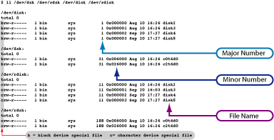
The first two items in the list above are determined by the major number of a device special file, the latter two items are determined by the minor number of a device special file. Device Special Files (DSFs) are comprised of the following parts:
The three parts of a device file can be viewed using the ll (ls -l) command. For example: You can view, in more human readable form, information contained in the device special file using the /usr/sbin/lssf command. For example:
The /usr/sbin/ioscan command will also show you hardware path information about the devices on your system: Here is the legacy view of the disk drives on a system:
Here is the agile view of the same disk drives (showing the virtual LUN hardware paths rather than the actual hardware paths):
Beginning with HP-UX 11i version 3, mass storage devices are referenced by device instances rather than by the hardware paths to the devices. This has many benefits over the previous addressing scheme which associated a given device special file with the hardware path to a device. Device hardware addressing for mass storage devices is now fluid, automatic, and transparent. This has many benefits. Agile device addressing allows for hardware paths to change between system boots (for example, if a LUN is moved from one HBA to another while a server is shutdown) and for SAN configurations to change without requiring changes to device special files (and therefore without requiring changes to other configuration files). If you replace a disk associated with a persistent device special file (the type of device special files that provide agile device addressing), you can use the io_redirect_dsf command to update the persistent device special file to reference the replacement disk. For details, see the manpage io_redirect_dsf(1M). Because of a limitation in device special file minor numbers, a server was previously limited to 256 bus instances. Using agile device addressing you can now address more than 256 bus instances. Agile device addressing also allows you to address a greater number of LUNs. HP-UX 11i version 3 supports up to 16,384 LUNs. Each LUN can have up to 32 physical I/O paths. HP-UX 11i version 3 automatically discovers and configures new physical I/O paths to a LUN and balances data flowing through the various paths to a given device using one of the following load-balancing policies:
Use the scsimgr command to specify which of the previous policies should be used for a given device.
HP-UX can also automatically re-balance the loads on remaining data paths to a LUN should one or more of those paths fail.
Device Special Files are located in the /dev directory and many are organized in a series of sub-directories within /dev. Two of these directories contain the persistent device special files defining the physical disk drives on a server:
Within the previous directories, files have names in the format “diskN” (where “N” is the instance number of the disk). An optional part of a device file name for a disk can be appended to represent disk partition numbers. By convention, in the absence of this optional part of the device file name the name represents an entire disk. This optional part expands the format of the name to be diskN_p# (where p# represents the partition number, tape density, or other information). The following directories still exist in HP-UX 11i version 3 for backwards compatibility. They contain the legacy device special files defining the physical drives on a server (the legacy form):
Within these directories, files have names in the format “c#t#d#” (where c# represents the controller instance number, t# represents the SCSI target number, and d# represents the SCSI LUN number). With legacy device special files that are associated with disks an optional part of the filename can represent disk partition numbers. By convention, in the absence of this optional part of the device file name the name represents an entire disk. This optional part expands the format of the name to be c#t#d#s# (where s# represents the partition number, tape density, or other information). Hardware paths, as the name implies, define the physical paths that data travels to reach devices. In HP-UX 11i version 3 there are three formats to specific hardware paths to mass storage devices. This is the format used in releases prior to HP-UX 11i Version 3. It is composed of a series of bus-nexus addresses separated by slash characters (“/”) leading to the host bus adapter (HBA); beneath the HBA, additional address elements are separated by periods (“.”). For directly connected devices, the addressing can be a simple target and LUN: 0/0/2/0.1.7.0 For SCSI-3 devices connected through a storage area network (SAN), legacy addressing is emulated with a domain, area, port, virtual bus, virtual target, and virtual LUN: 0/2/1/0.1.5.0.0.3.7 This format is used for addressing LUNs in agile mode. It is identical to the legacy hardware path format up to the host bus adapter (HBA). Beneath the HBA, two additional address elements are represented (in hexadecimal):
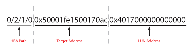
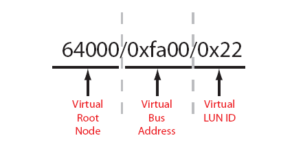
0/2/1/0.0x50001fe1500170ac.0x4017000000000000 is an example of a SCSI-3 hardware path. Because devices can have multiple physical hardware paths, a virtualized LUN hardware path is needed so that the hardware path that a persistent device special file maps to remains the same even when the underlying physical hardware path elements change. Instead of a series of bus-nexus addresses (corresponding to specific hardware paths) leading to the HBA, virtual hardware paths use a virtual bus-nexus (known as the virtual root node) with an address of 64000. Addressing beneath that virtual root node consists of a virtual bus address and a virtual LUN ID, delimited by slash characters (“/”). 64000/0xfa00/0x22 is an example of a virtual hardware address. Example 3-2 Hardware Path Format Summary The three formats described previous are different ways of referring to the same LUN, so a single LUN could have all of the following addresses:
In the previous example the LUN has four physical hardware paths. The first four lines represent them using the legacy hardware path format, the next four lines represent them using the SCSI-3 hardware path format, and the final line represents the single virtual hardware path (used for all four physical paths). HP-UX 11i version 3 commands will accept any of these three formats to specify a hardware path to a LUN. Here is a list of key commands used for managing device special files:
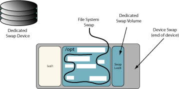
Swap space is where HP-UX stores unneeded pages of memory from running processes, a process called virtual memory paging (or simply paging) because the chunks of data moved in and out of physical RAM are called pages. This enables HP-UX to use much more memory than physically exists on a server. There are three types of swap space used for paging operations: Swap space is initially allocated when you configure your disks. Device swap space occupies a logical volume or disk partition that is typically reserved expressly for paging purposes. This space may also be configured as a dump area but doing so has implications for memory dump integrity if a crash occurs. See “Using a Device for Both Paging and Dumping (System Recovery Time)”. Because, when HP-UX is running, the device is used exclusively for paging, you cannot also store files on it.
Device swap can only be used locally; it cannot be accessed remotely by clients using network disk access protocols. Device swap is quickly accessed because HP-UX can get to the logical volume or disk partition directly to perform large writes or reads. If the device swap space you have configured on your server is not enough and you have no more devices that you can dedicate for that device swap space, you can configure file system swap space. File system swap allows for extra swap space if there is an occasional need for more than is allocated as device swap space. It is used only when device swap space is insufficient. File system swap space is configured as additional swap space to be allocated from unused space within a file system. Because file system swap requires the system to perform a greater amount of processing it is usually slower than device swap and should not be used as a permanent replacement for a sufficient amount of device swap space. It is best for the occasional overflow of device swap space. The file system used for swap can be either a local or a remote file system. Cluster clients can use remote file system swap for their swap needs. Swapping to a remote file system is slower than swapping to a local file system and is not encouraged if local device swap or local file system swap is available. Pseudo Swap is very different than device swap space or file system swap space. It is one of the technologies that allow you to more efficiently utilize the resources on your system. Pseudo swap “space” does not really exist; HP-UX just behaves as though it has an extra amount of swap space. Pseudo swap takes advantage of the fact that not all swap space that is reserved is actually used. This allows a greater number of processes to run in memory than could be supported by configured swap devices. Pseudo swap is best used with large memory systems. If you choose to use the pseudo swap capability (actually, it is enabled by default), an amount of pseudo swap space equal to 7/8ths of the amount of physical ram available to your server, nPartition, or virtual partition is used as pseudo swap. Another technology that takes advantage of the fact that not all swap space that is reserved is actually used is lazy swap. The lazy swap feature causes HP-UX to not reserve swap space for a process-private page until the associated process actually modifies the page. This can significantly reduce the amount of allocated swap space. Lazy swap is configured on a process by process basis. There are programmatic ways to enable lazy swap or a user can modify a binary executable file to enable lazy swap by using the +z option to the chatr command. See the chatr(1) manpage for details. HP-UX must have at least one device swap area available when it boots. This area is known as the primary swap area.[4] Primary swap, by default, is located on the same disk as the root file system (though in a different logical volume). Use the swapon command (see swapon(1M)) to define swap space. Other swap space may be used in addition to primary swap. This is known as secondary swap space. If you are using device swap as your secondary swap space, for better performance allocate the secondary swap space on a disk drive other than where the primary swap is located. Your swap space must be large enough to hold all the processes that could be running at your system’s peak usage times. If your system performance is good, and, in particular, if you are not getting swap errors such as “Out of Memory” or those to the effect that a process was killed due to no swap space, then your system has adequate swap space. Unless the amount of physical memory on your system is extremely large, the minimum amount of swap space should equal the amount of physical memory on the system. In general, size your server’s swap space to be roughly two to four times the amount of physical memory that is used by HP-UX on your server, nPartition, or virtual partition. Swap space usage increases with system load. If you are adding (or removing) a large number of users or applications, you will probably need to re-evaluate your swap space needs. Once you know or suspect that you will have to increase (or decrease) your swap space, you should estimate your swap space requirements. You can estimate the amount of swap space you need by adding the memory requirements of the applications you expect to run (simultaneously) on your system to the amount of physical memory you have. When HP-UX is in the earliest stages of the boot sequence, the system begins by paging on only a single device so that only one disk is required at boot time. During the processing of the startup script /sbin/init.d/swap_start, calls to swapon enable any additional paging areas, if any are defined in the file /etc/fstab. Should you find the need for additional paging space while your system is running, you can also run the swapon command to manually enable additional space. See the swapon(1M) and fstab(4) manpages for details. Sometimes, you can disable swap space. In order to be able to disable paging to swap areas:
Use the swapoff command to disable paging to a specific swap area. For example:
There are some guidelines to consider when configuring swap space on your system. Most of these are focused on maximizing the performance of HP-UX. Use the following guidelines to configure the most commonly used type of swap space, device swap:
When you need more swap space and you have no devices available for additional device swap, or if you need to swap to a remote system, you can dynamically add file system swap to your system. Use the following guidelines:
When you add swap areas, you can assign a priority to each. Priorities range from 0 (the highest) to 10 (the lowest). HP-UX uses swap areas with higher priority first. And, HP-UX gives device swap priority over file system swap when each has the same priority. Here are the guidelines you should use:
The following manpages contain important information on configuring swap space:
The following kernel tunables affect paging activities on HP-UX: [3] In some cases, new hardware is automatically discovered and associated persistent device special files are created, even before ioscan is run. However, if you have new hardware with no associated device special files, insf can create them for you. [4] Primary swap is not mandatory if pseudo swap is enabled, however, it is strongly recommended. |
|||||||||||||||||||||||||||||||||||||||||||||||||||||||||||||||||||||||||||||||||||||||||||||||||||||||||||||||||||||||||||||||||||||||||||||||||||||||||||||||||||||||||||
|
|||||||||||||||