|
|

In an IGX-only network, IGX nodes function as both network backbones and network access points. In a mixed network, an IGX node can perform a variety of functions, including traffic routing and bandwidth optimization, network administration and synchronization, and job management.
For information about the BPX, see Chapter 1, "The BPX Switch: Functional Overview ," in the Cisco BPX 8600 Series Installation and Configuration guide.
In a network, a node represents a chassis or other hardware point where network traffic is switched or routed to the next node. Because the IGX WAN switch can handle many different types of traffic, the IGX chassis can function as a node in many different networking environments. In addition, the modular design of the chassis features removable service modules that can provision the node for different networking technologies, so that the IGX node can function as a node in multiple networks simultaneously, such as a Frame Relay network and an ATM network.
For example, an IGX node can service an ATM network through a UXM or UXM-E service module installed in slot 3, while a UFM service module in slot 4 allows the IGX node to participate in a FR network. Interworking between different networking technologies also allows the two networks to be functionally attached.
In one of the most common network designs using the IGX, the IGX node functions as an edge switch for the network, with an attached edge router handling routing of traffic coming into the network attached to the IGX. With an installed URM card, this IP routing can be handled within the IGX chassis, eliminating the need for a separate external router.
Available clock sources are defined within the network as primary (p), secondary (s), or tertiary (t). Each trunk that can pass clock synchronization is defined. Each network node's clock is locked to the highest-level clock source available. If multiple, equal clock sources are available, each node chooses the closest one (measured in number of hops).
If there is no primary, secondary, or tertiary clock source defined or working in a network, then the internal oscillator of one node is automatically selected as the active network clock source.
Whenever a clock source changes (because of a line repair or an operator's command, for example) the node ensures that the clock path remains hierarchical. Also, whenever a subnetwork is merged with another subnetwork, each node in the new network verifies that it has the nearest, most stable clock that is available.
A continuous clock test compares the frequency of the node clock source to a reference on the control card. If it detects a clock source outside preset frequency limits, the controller declares the source defective and selects another source.
Ordinarily, a network's clock sources and line characteristics are configured as part of the node installation process. Thereafter, clock sources are redefined when a network is reconfigured or a line status is changed.
Clock sources are manually defined as primary, secondary, or tertiary. The designation typically depends on the stability of the clock source. Considerations for assessing and defining clock sources include:
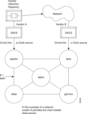
A plesiochronous network is a network in which there are two or more independent, active clock sources. For example, a network in which multiple vendors provide multiple lines that require clock mastership can be a plesiochronous network. Figure 3-1 depicts clock source reliability.
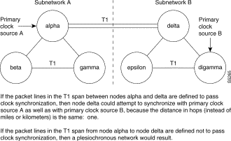
Refer to Figure 3-2. One trunk parameter has the ability to pass a clock. A trunk passes a clock if the clock information transmitted from one end arrives as the identical clock at the other end. Many trunks pass clock. Trunks that do not normally pass clock include:
A long-distance line that passes through another provider's network may or may not pass clock. The default ability for an IGX trunk is to pass clock. The following applies to clocks:
For more information on IGX service modules, refer to the "Service Modules" section.
IGX nodes must be set up before you begin building the network. When adding a node to a pre-existing network, perform basic node configuration tasks before joining the new node and the existing network.
 |
Caution Different nodes in a network may be using different releases of card firmware, switch software or Cisco IOS software. When integrating a new node into a network, or when upgrading firmware, switch software or Cisco IOS software, refer to the Compatibility Matrix at http://www.cisco.com/kobayashi/sw-center/sw-wan.shtml. Incompatibilities between firmware, switch software, and the Cisco IOS software can cause operational problems. |
Step 2 Configure the node name (see the "Naming a Node" section), and node time zone (see the "Configuring the Time Zone" section).
Step 3 If the node will be the network's primary node, configure the node date and node time (see the "Configuring the Date and Time" section).
Step 4 Configure users and security features for the node.
Step 5 Configure card redundancy (see the "Specifying Card Redundancy" section).
You can configure the IGX node for the following tasks:
In an operational network, each node requires a unique node name. To change the factory-default NODENAME to your chosen node name, use the switch software cnfname command.
 |
Tip In many networks, the node is named for its physical location, to help those monitoring the network more quickly identify problems that may be related to geographic area. |
To change a node name, use the switch software cnfname command. The new node name is distributed to other nodes in the network.
Configuring the time zone allows the node's time display to show local time, regardless of where the other nodes are located.
To set the node's time zone, use the switch software cnftmzn command.
To configure the node's date and time, use the switch software cnfdate command.
An interface shelf is a non-routing device that drives ATM cells to and from an IGX routing hub in a tiered network. (An interface shelf is also sometimes referred to as a feeder shelf.) An interface shelf can be either an IGX or MGX 8850 node configured as an interface shelf, or an MGX 8220 interface shelf.
Because tiered network capability is a purchased option, for an IGX node to serve as an interface shelf, personnel in the Technical Assistance Center (TAC) must first configure it for that purpose (for information on contacting TAC, see "Obtaining Technical Assistance" section).
To add an interface shelf, use the addshelf command. To delete a feeder shelf, use the delshelf command. To view conditions on a feeder trunk, use the dspnode command.
 |
Note The addshelf and addtrk commands are mutually exclusive. |
IGX/AF is the designation of an IGX node serving as an interface shelf. Display commands such as dspnw and dspnode display these designations. The dspnode command identifies the hub and feeder nodes and shows the alarm status. The designation for an MGX 8220 shelf serving as an interface shelf is AXIS. The designation for an MGX 8850 serving as an interface shelf is AAL5. The designation for an SES (Service Expansion Shelf) shelf serving as an interface shelf is also AAL5.
The following procedure applies when adding any supported feeder to an IGX routing node. Table 3-1 displays the commands to configure an SES (Service Expansion Shelf) as a feeder to an IGX 8400 routing hub.
Table 3-1 Adding an Interface Shelf
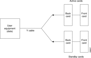
You can set up card redundancy by installing two identical front and back card sets, connecting them with a Y-cable on each paired port, then specifying redundancy with the switch software addyred command. Redundancy applies to the entire card and is not port or line-specific.
Table 3-2 Specifying Card Redundancy
| Command | Description |
|---|---|
Specifies the slots of the primary and secondary cards that form the redundant pair. |
|
Disables Y-cable redundancy for the card set in the specified primary slot number. |
|
During normal operation, the primary set is active and carrying traffic, while the secondary set is in standby. The primary set configuration is the configuration for both the primary and redundant set. If you reset the primary cards or the primary card set becomes inactive for another reason, the secondary card set becomes active.
The following requirements apply to redundant card sets:
Figure 3-3 illustrates the typical Y-cable connection of primary and secondary card sets. The single end of a Y-cable (or base of the Y) goes to the user equipment. One of the two connectors at the split end goes to the primary back card, and the other connector goes to the secondary back card.
Switching between Y-redundant cards occurs only if the standby card set is in a standby or standby-T state (but not failed).
|
Note Terminating connections is possible only at a primary slot and not at a secondary slot. See the addcon command description in the Cisco WAN Switching Command Reference . |
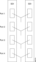
On multiport card sets, each primary port is connected by a Y-cable to a secondary (redundant) port. Port 1 of the primary card set must be paired to port 1 of the secondary card set, and so on. Figure 3-4 illustrates the cabling for a multiport card set.
If the secondary card set becomes active, the primary card set goes into the standby state. For the primary card set to serve as a backup, it must be a complete set and not have failed status.
If your system is configured to control an external device, such as a multiplexer, you can establish a window session, any characters you type at the control terminal go to the external device for processing. Any characters generated by the external device appear on the control terminal screen.
The window command establishes a window session. You can use this command only if the external device connects to the local node. You can, however, enter the window command during a virtual terminal session so that you have a window session with any external device in the network. To start a window session:
Step 2 Configure the port and the port function with the switch software cnfterm and cnftermfunc commands.
Step 3 Configure a 1-8 character escape sequence for the window session with the switch software cnftermfunc command. Write the escape sequence here: ______________________.
Step 4 Determine whether the external window device is cabled to the node's control terminal port (c) or auxiliary port (a).
Step 5 Start the window session with the switch software window command. If the external device is connected to the auxiliary port, use window a. If the external device is connected to the control terminal port, use window c.
Step 6 Enter commands and send data to the external device.
You might notice a slight transfer delay in transmission, because of the IGX/BPX bundling of characters before transmitting them. Transfers are delayed until the transfer buffer is filled, or until the keyboard has been inactive for over 50 ms.
Step 7 Using the escape sequence configured in Step 3, end the window session.
|
Tip The default escape sequence is ^^. If the default sequence does not work and you do not know the configured escape sequence, leave the keyboard idle for four minutes. After four minutes, the system terminates the window session. |
The following sections explain how to manage your IGX network. Managing your network involves optimizing traffic routing and bandwidth, synchronizing the network, performing network administration tasks, and managing jobs.
To achieve peak network performance, the routing of traffic and the use of available bandwidth is configurable. The information used in configuring traffic routing and bandwidth is gathered from historical network trends. The tasks required to optimize the network are specifying channel utilization (see the "Specifying Channel Utilization" section), specifying the class of service (including use of the priority bumping feature—see the "Specifying Class of Service" section), and managing bandwidth.
|
Tip For information on the switch software commands listed in this section, see the full command description in the Cisco WAN Switching Command Reference . |
Use the cnfchutl command to specify the expected utilization of Frame Relay, data, or voice channel as a percentage of the channel's total capacity. The specified value can be in the range of 0 to 100 percent; 100 percent is the default for data and Frame Relay channels. The default for voice channels is 60 percent. To display the utilization of a particular trunk, use the dsptrkutl command. This command displays a details on the packets transmitted over the trunk. The user can specify the rate in seconds at which the screen is updated. Use the dspload command to display the load for a specified trunk at a node.
Use the cnfcos command to specify a class of service (CoS) for a Frame Relay, data, or voice channel connection. The class of service is the delay in seconds before the network reroutes a connection in the event of a trunk failure. The range is 0 to 15. By spreading out the CoS numbers to vary the rerouting delay, one class of connections has a chance to reroute before the other class starts to reroute.
Priority bumping allows both BPX and IGX connections that are classified as more important (via CoS value) to bump existing connections that are less important, when network resources become scarce. While the existing Automatic Routing Management feature is capable of automatically redirecting all failed connections onto other paths, use the priority bumping command, cnfbmpparm, to activate the priority bumping feature in order to retain important connections when network resources are diminished to a point when all connections cannot be sustained. Network resources are reclaimed for the more important connections by bumping (or derouting) the less important connections. Priority bumping is triggered by insufficient resources (such as bandwidth) resulting from a number of events, including changes to the network generated by the addcon, upcon, cnfcon, cnfpref, cnftrk, and deltrk commands, by a trunk line or card failure, or by a node failure. The most typical event is a trunk failure.
In priority bumping, connections are defined by their Class of Service (CoS) value. Connections tagged with the lowest CoS, zero, are the most important to maintain. Connections tagged with the highest CoS, 15, have the lowest priority. Connections that have a CoS value in between 0 and 15 are progressively less important as they ascend upward.
The CoS values are categorized into a set of 8 bands. These bands can be configured to meet the specific needs of each network. For information on the default settings used when priority bumping is enabled, see Table 3-3.
|
Note Configuring priority bumping requires a thorough knowledge of AutoRouting capabilities (also known as Automatic Routing Management) available bandwidth, and CoS values. |
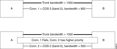
For an example of how this feature works, refer to Figure 3-5. If a trunk is established between switches A and B with a bandwidth of 1000 load units, it can support connection 1 (Conn. 1) with a bandwidth of 800. However, if we add a second connection (Conn. 2) with a bandwidth of 500, the trunk can no longer support both connections.
connection 1 (800) + connection 2 (500) = total bandwidth of 1300
When priority bumping is enabled the least important connection is bumped.
The lower CoS connection has the higher priority. Connection 1 with a CoS of 5 is failed in order for connection 2 traffic (with a CoS of 0) to flow without interruption.
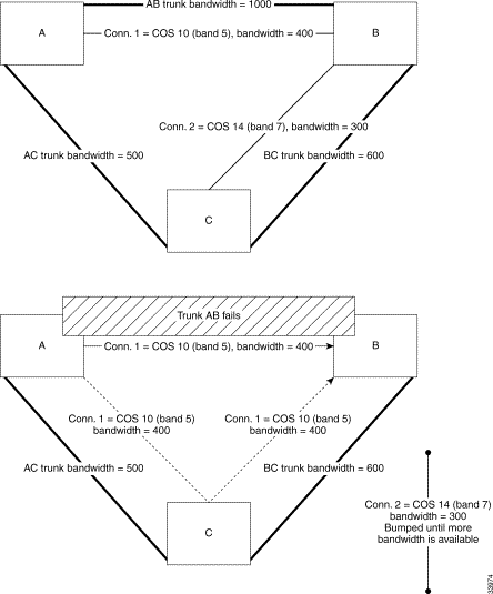
An example with three nodes is illustrated in Figure 3-6. Three trunks are established:
Table 3-4 Trunks Illustrated in Figure 3-6
| Trunk | Bandwidth |
Two connections are established:
Table 3-5 Connections Illustrated in Figure 3-6
| Connection | Nodes | CoS | Band | Bandwidth |
|---|---|---|---|---|
All traffic on the connections is uninterrupted, but if Trunk AB fails, Trunk BC, with a bandwidth of 600, cannot handle the total bandwidth of both connections (700). Connection 1 is in Band 5; connection 2 is in Band 7. The lower the band, the higher the priority. Connection 2 is bumped to accommodate connection 1 with the higher priority.
|
Note For more information about the bumping or rerouting process, refer to an update on this topic at http://www.cisco.com/univercd/cc/td/doc/product/wanbu/bpx8600/9_3_0/rnotes/9300rn.htm |
The following tasks are included in routine network administration:
Logging in to a node is a two-step process that requires you to enter a User ID and a password. The system or network administrator can provide a User ID and password to you. The User ID can be up to 12 characters. To protect the security of the system, you should change your password regularly. Only your system administrator can change the User ID. To log in to a node:
Step 2 Enter your password at the "Enter Password" prompt. For initial login, enter the password that the system administrator provides. You can change the password with the cnfpwd command.
After you log in, the system is ready and so prompts you for the next command.
When you have completed a session and want to log off, use the bye command. This command returns the display to the initial system sign-on prompt. If you enter the bye command when you have a virtual terminal connection to another node, the bye command ends the virtual terminal session and returns to the local session. To end the local session and log off the system, again enter the bye command.
To change the password given to you by your system administrator, or to change your present password to a different one, perform the following. To ensure the security of your system, your password should be changed on a regular basis. See the system administrator for the recommended frequency of change.
Step 2 Enter your current password. The system prompts for a new password.
Step 3 Enter a new password. Passwords must have 6 to 15 characters. The system prompts you to confirm the new password by typing it again.
Network synchronization includes specification of primary, secondary, and tertiary clock sources. The latter two sources serve as backups in case of clock failures. The cnfclksrc command specifies the source of a clock and can remove a previously specified clock source. Multiple primary sources, multiple secondary sources, and multiple tertiary sources are allowed.
Table 3-6 Switch Software Commands Used in IGX Clock Synchronization
|
Tip For information on the switch software commands listed in this section, see the full command description in the Cisco WAN Switching Command Reference . |
A job is a user-specified string of commands. A job can automatically run on a prearranged schedule or on an event trigger. This section describes how to:
The system assigns a number to a new job. This job number identifies the job and is a required parameter for most job control commands. When you create a new job, your privilege level is automatically saved as the privilege level of the job. Use only commands that are available at your privilege level in your job specification. For example, a user whose privilege level is 3 cannot include the addtrk command in a job because addtrk requires a level 1 privilege. This privilege requirement also applies to other job functions, such as running, editing, or stopping a job.
|
Tip Not all switch software commands can run as a part of a job. See the full command description in the Cisco WAN Switching Command Reference to see which commands are allowed in a job. |
Consider the following information before creating a job:
Consider the following information before running a job:
Consider the following information before stopping a job:
To display a job, use the following commands:
The following information applies to editing a job. Before using an edited job, test it to ensure that it works.
Use the deljob command to delete a job. You cannot delete a job that is running. If necessary, stop the job with the stopjob command before deleting it.
The following information applies to creating a job trigger:
This section describes how to diagnose problems.
The IGX operating system software does most of the IGX monitoring and maintenance. The only action that qualifies as preventive maintenance is checking the power supplies.
|
Tip For information on the switch software commands listed in this section, see the full command description in the Cisco WAN Switching Command Reference . |
You cannot directly measure voltages on the AC power supplies in an IGX node. If a problem exists with one of the supplies, one or both the DC and AC LEDs turns off. Refer to the chapter on repair and replacement for instructions on re-seating or replacing an AC power supply.
After you install new or additional cards in the node, check the LEDs on the power supplies to make sure the cards have not put an excessive load on the power supplies.
|
Note Use the switch software dsppwr command to see AC power supply information. |
This section describes elementary troubleshooting procedures and briefly describes the commands used when troubleshooting an IGX node. (These commands are described in detail in the Cisco WAN Switching Command Reference.) This set of procedures is not exhaustive and does not take into account any of the diagnostic or network tools available to troubleshoot the IGX node.
|
Caution Do not perform any disruptive tests or repairs to the IGX node without first calling the Technical Assistance Center (TAC—see the "Obtaining Technical Assistance" section). Cisco personnel can help isolate the fault and provide repair information. |
This section contains the following topics:
The IGX node regularly runs self-tests to ensure proper function. When the node finds an error condition that affects operation, it deactivates the affected card and then activates a standby card if one is available.
|
Caution The fail LED on a card indicates that an error occurred. Try resetting the light with the resetcd f command. |
The first step in troubleshooting an IGX node is to check the condition of the system by displaying alarm conditions throughout the system. To see a summary of all of the alarms on an IGX node, use the dspalms command. The alarms summary includes the following:
To display alarms enter the dspalms command.
If the screen indicates a failure, refer to the commands in Table 3-7 to further isolate the fault.
When a card indicates a failed condition on the alarm summary screen, use the dspcds command to display the status of the cards on a node. The information displayed for each card type includes the slot number, software revision level, and card status.
|
Note If dspcds or any other command incorrectly states the IGX model (for example, stating that an IGX 8420 node is an IGX 8430 node), check the jumper switch W6 on the SCM. A jumpered W6 indicates an IGX 8420 node. An open W6 indicates an IGX 8430 node. For more information, see the "Preparing the Cards" section in Chapter 3 of the Cisco IGX 8400 Series Installation Guide. |
See Table 3-8 for status descriptions for each card type.
|
Note Cards with an "F" status (nonterminal failure) are activated only when necessary (for example, when there is no card of that type available). Cards with a failed status are never activated. |
Several user commands help you test the node status. The switch software CLI commands are:
For details on these commands, see the Cisco WAN Switching Command Reference .
Loopback tests are available to help diagnose the state of the IGX system. The CLI commands for activating these tests are:
For detailed information on these commands, see the Cisco WAN Switching Command Reference .
The HDM/SDI or LDM/LDI card set can be tested as a pair at the local node using external test equipment such as a Bit Error Rate Tester (BERT). This can be useful in isolating dribbling error rates in either the cards or the transmission facility. This test checks the data path from the electrical interface at the port through the card set to the Cellbus in both directions of transmission.
|
Note This is a disruptive test. Notify your network administrator before performing this test. |
To perform this test, proceed as follows:
Step 2 Set up an internal loopback on the Frame Relay port to be tested using the addloclp command.
Step 3 Turn on the BERT, make sure it indicates circuit continuity, and observe the indicated error rate.
Step 4 If there are any errors indicated, first replace the back card and retest. If the errors remain, then replace the front card and retest.
Step 5 When the test is complete, disconnect the BERT and reconnect the data cable. Release the local loopback by using the dellp command.
Step 6 Repeat at the node at the other end of the connection if necessary.
Full command descriptions for the switch software commands listed in Table 3-9 can be accessed at one of the following links:
For information on IGX trunks, refer to Chapter 5, "Cisco IGX 8400 Series Trunks"
For installation and basic configuration information, see the Cisco IGX 8400 Series Installation Guide, Chapter 1, "Cisco IGX 8400 Series Product Overview"
For more information on switch software commands, refer to the Cisco WAN Switching Command Reference, Chapter 1, "Command Line Fundamentals ."
![]()
![]()
![]()
![]()
![]()
![]()
![]()
![]()
Posted: Mon May 12 15:34:38 PDT 2003
All contents are Copyright © 1992--2003 Cisco Systems, Inc. All rights reserved.
Important Notices and Privacy Statement.