|
|

Table Of Contents
Alphabetical List of Commands addad through cpytrkict
. (a period) (display command history)
addalmslot (add alarm card set)
addapsln/delapsln (add/delete SONET APS line)
addcon (add a data channel connection)
addcon (add channel voice connections)
addcon (add a Frame Relay connection)
addcon (add an ATM connection)
PCR Values and Traffic Policing
addctrlr (add a VSI controller to an IGX node)
addctrlr (add VSI capabilities to an AAL5 feeder interface (BPX))
addlnloclp (add local loopback to line)
addlnlocrmtlp (add local-remote loopback to BPX line)
addloclp (add local loopback to connections on a port)
addlocrmtlp (add local-remote loopback in a tiered network)
addport (add ATM or Frame Relay port)
addrmtlp (add remote loopback to connections)
addshelf (add interface shelf or controller to a routing node or hub)
addtrk (add a trunk between nodes)
addtrkred (add trunk redundancy)
addyred (add Y-cable redundancy)
APS 1+1 Environment (Redundant Back Cards with Front Card Redundancy)
burnfwrev (burn firmware image into cards)
burnrtrcnf (burn router configuration file)
chklm (check node loading model)
clrcderrs (clear detailed card errors)
clrchstats (clear channel statistics)
clrcnf (clear configuration memory)
clreventq (clear event queues from the fail handler)
clrfrcportstats (clear FRC/FRM port statistics)
clrlnalm (clear circuit line alarm)
clrmsgalm (clear message alarm)
clrphyslnalm (clear physical line alarm)
clrphyslnerrs (clear UXM physical line errors)
clrportstats (clear port statistics)
clrrtrcnf (clear router configuration file)
clrscrn (clear terminal screen)
clrslotalms (clear slot alarms)
clrsloterrs (clear slot errors)
clrtrkerrs (clear trunk errors)
clrtrkstats (clear trunk statistics)
cnfabrparm (configure assigned bit rate queue parameters)
cnfapsln (configure APS line parameters)
cnfatmcls (configure class template)
cnfbmpparm (configure priority bumping)
cnfbpnv (set backplane type to new)
cnfbusbw (configure UXM card bus bandwidth)
cnfcassw (configure CAS switching)
cnfcdparm (configure card parameters)
Multilevel Channel Statistics Support
cnfcdpparm (configure CVM card parameters)
cnfcftst (configure communication fail test pattern)
cnfchadv (configure channel adaptive voice)
cnfchdfm (configure channel DFM)
cnfchdl (configure dial type for channels)
cnfchec (configure channel echo canceller)
cnfcheia (configure EIA update rate for channels)
cnfchfax (configure FAX modem detection for channels)
cnfchgn (configure gain insertion for channels)
cnfchpri (configure Frame Relay channel priority)
cnfchstats (configure channel statistics collection)
cnfchts (configure channel timestamp)
cnfchutl (configure channel utilization)
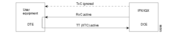
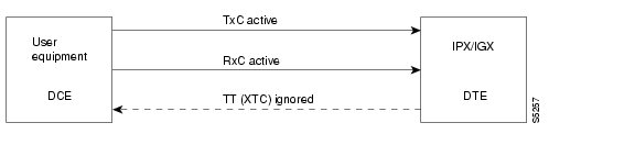
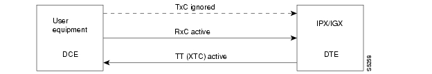
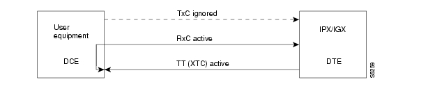
cnfcldir (configure control lead direction)
cnfclksrc (configure network clock source)
cnfclnparm (configure circuit line parameter)
cnfclnsigparm (configure circuit line signaling parameters)
cnfcls (configure class template)
cnfcmb (configure combined timeout parameters)
cnfcmparm (configure connection management parameters)
cnfcond (configure conditioning template)
cnfctrlr (configure controller with new VPI and start_VCI for control channels)
cnfdate (configure date and time)
cnfdch (configure voice connection for idle code suppression)
cnfdchtp (configure data channel interface type)
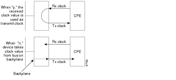
cnfdclk (configure data channel clocking type)
cnfdiagparm (configure diagnostic test parameters)
cnfdlparm (configure download parameters)
cnfecparm (configure echo canceller parameters)
cnffrcls (configure Frame Relay class)
cnffrcon (configure Frame Relay connection)
cnffrcport (configure Frame Relay port)
cnffstparm (configure ForeSight node parameters)
cnffunc (configure system functions)
cnffwswinit (configure FW/SW download initiator IP address)
cnfict (configure interface control template)
cnfleadmon (monitor LDM/HDM data port leads)
cnflnalm (configure line alarm)
cnflnparm (configure ATM line card parameters)
cnflnpass (configure line pass-through)
cnflnsigparm (configure line signaling parameters)
cnflnstats (configure line statistics collection)
cnfmxbutil (configure muxbus utilization)
cnfnodeparm (configure node parameter)
cnfnwip (configure network IP address)
cnfoamseg (configure connection OAM segment status)
cnfphyslnstats (configure physical line statistics)
cnfport (configure Frame Relay port)
ELMI Neighbor Discovery for UFM
Automatic Routing Management to PNNI Migration
Traffic Shaping on the UXM and URM
cnfportq (configure port queue parameters)
cnfportstats (configure port statistics collection)
cnfpref (configured preferred route for connections)
cnfprt (configure printing functions)
cnfrcvsig (configure receive signaling)
cnfrobparm (configure robust alarms parameters)
cnfrrcpu (configure CPU-based reroute throttling level parameters)
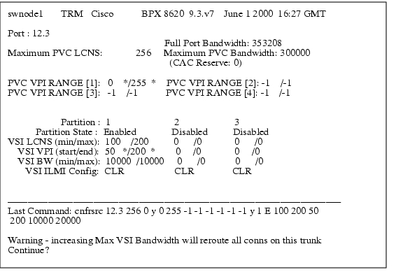
cnfrsrc (configure VSI resources for IGX)
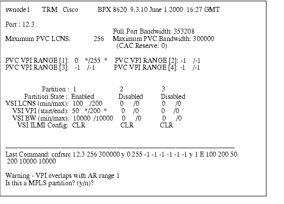
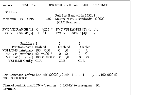
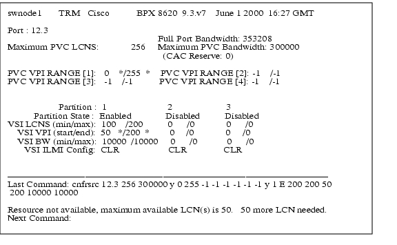
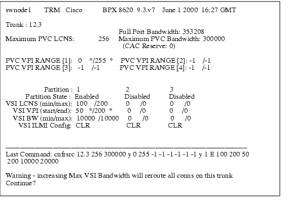
cnfrsrc (configuring VSI resources for BPX)
cnfrtcost (display connection loading)
cnfrtr (configure router configuration parameters)
URM Remote Router Configuration Feature
cnfrtrcnfmastip (configure router configuration download initiator TFTP server IP)
cnfrtrparm (configure router service parameters)
cnfslotalm (configure slot alarm parameters)
cnfslotstats (configure slot statistics collection)
cnfsnmp (configure SNMP parameters)
cnfstatmast (configure statistics master SV+ address)
cnfstatparms (configure TFPT statistics parameters)
cnfsysparm (configure system parameters)
cnftcpparm (configure TCP parameters)
cnfterm (configure terminal port)
cnftermfunc (configure terminal port functions)
cnftlparm (configure trunk-based loading parameters)
Physical and Virtual Trunk Configuration
IMA-Compliant Trunk Configuration
Subrate and Fractional Trunk Configuration
cnftrkalm (configure trunk alarms)
cnftrkict (configure trunk interface control template)
cnftrkparm (configure trunk card parameters)
cnftrkstats (configure trunk statistics collection)
cnftstparm (configure card test parameters)
cnfuiparm (configure user interface parameters)
cnfuvmchparm (configure channel parameters on a UVM)
cnfvchparm (configure voice channel parameter)
cnfvchtp (configure interface type for voice channels)
cnfvsiif (assign a service class template to an interface)
cnfvsipart (configure VSI ILMI on VSI partition)
cnfxmtsig (configure transmit signaling)
compactrsrc (compact resources)
cpyict (copy interface control templates)
cpytrkict (copy trunk interface control template)
Alphabetical List of Commands addad through cpytrkict
. (a period) (display command history)
Displays the twelve (12) most recently used commands. To reuse one of these commands, enter the associated number. The command appears on the command entry line, where you can edit or re-execute a command.
To edit the command line: backspace through the command's arguments and type in a new value or backspace without typing a new value to restart the command at the cursor position.
Syntax
. (A period)
Attributes
Example
Display the command history.
. (A period)
sw180 TN Cisco IGX 8420 9.3.g0 Oct. 20 2000 09:26 GMTCommand history12: addyred 411: dspcds10: dspcd 69: dspcd 98: addyred 6 97: dsptrks6: addshelf 5.15: upcd4: upcd 63: dspcds2: dncd 91: upcd 9Last Command: upcd 9Next Command:addalmslot (add alarm card set)
Enables the MAJOR and MINOR alarm indicators on an Alarm Relay Card (ARC) or Alarm Relay Module (ARM) front card. It also configures the slot to provide external alarms from the Alarm Relay Interface (ARI) back card.
Use this command at each node equipped to provide external alarm indications to the customer alarm reporting system. The slot specified for the ARC or ARM may be any shelf slot, but is usually the slot farthest to the right.
Upon executing the command, the system places the alarm card set in the active state and displays the current alarm status.
Syntax
addalmslot <slot number>
Parameter
Attributes
Related Commands
delalmslot, dspalms
Example
Enable alarm reporting from slot 16 in a node. (The system then displays alarm status.)
addalmslot 16
beta TRM YourID:1 IGX 8430 9.3 Apr. 13 2000 14:27 MSTAlarm summary (Configured alarm slots: 16)Connections Failed: NoneGroups Failed: NonePLN Alarms: 1 MajorCLN Alarms: NoneCards Failed: 1Missing Cards: NoneRemote Node Alarms: 1 MajorRemote Domain Alarms: NoneLast Command: addalmslot 16Next Command:addapsln/delapsln (add/delete SONET APS line)
Add a SONET APS (Automatic Protection Switching) line. The addapsln and delapsln command lets you add SONET APS (Automatic Protection Switching) for BXM OC-3 or OC-12 lines.
SONET APS is a standard that describes the switching of SONET lines from the active line to a standby line to provide hardware line redundancy. The SONET APS feature applies only to BXM OC-3 and OC-12 cards in this release.
When adding a new APS line pair, you must specify the desired APS protocol. The delapsln command deletes APS for the lines.
When the addapsln command executes, the switch software:
•
Verifies that the slot.port arguments support APS
•
•
•
Before the addapsln command has been executed, there is no working or protection line. The addapsln command defines which line is the working line and which line is the protection line. (For APS 1+1 Annex B, the active line is called the "primary section," and the standby line is called the "secondary section," which provides protection for the primary section.)
Feature Mismatching to Verify APS (Automatic Protection Switching) Support
The addapsln command, in addition to other configuration commands, performs mismatch verification on the BXM and UXM cards. For example, the addapsln command verifies whether the cards both have APS support configured. Refer to the BPX 8600 Series Installation and Configuration Manual.
Whenever you activate a feature by configuring it with CLI commands, switch software performs a verification to ensure that the hardware and firmware support the feature. For example, if you are attempting to add APS on a specific line (by using addapsln), and the BXM card does not support this feature, a warning message is displayed and the addition is not completed.
The Feature Mismatching capability does not mismatch cards unless the actual feature has been enabled on the card. This allows for a graceful card migration from an older release.
Syntax
addapsln <slot.port1> < slot.port2> <protocol>
You must enter the slot.port pair and the protocol option. If you do not enter the protocol option, a menu lists the options.
Parameters
slot.port1
The desired working line number
slot.port2
The desired protection line number
protocol
1: 1+1
2: 1:1
3: 1+1 Annex B
4: 1+1, ignore K1K2 bytes
Attributes
Related Commands
delapsln, cnfapsln, dspapsln, dsplog, dspalms
Example
Add an APS redundant pair, with Working line on slot 11, port 1; Protection line on slot 12, port 1; with "1" specifying APS 1+1 protocol.
addapsln 11.1 12.1 1
sw119 TRM StrataCom BPX 8620 9.3.10 Date/Time Not SetWork/Protect Actv Active Line Standby Line Current APS Last User(Work1/Work2)Line Alarm Status Alarm Status Alarm Status Switch Req11.1 12.1 NONE Deactivated APS Deactivated APS Deactivated ClearLast Command: addapsln 11.1 12.1 1addcon (add a data channel connection)
Establishes data channel connections between nodes in a network.
After you add a connection by using the addcon command, the node automatically routes the connection. The node where you execute addcon is the "owner" of the added connections. The concept of ownership is important because you must enter information about automatic rerouting and preferred routing at the node that owns the connection. See the cnfpref and cnfcos commands for more information on automatic rerouting. Before the node adds the connection, the proposed connection appears on the screen with a prompt for you to confirm the addition.
When applied to data connections, the addcon command adds a synchronous data connection to the network. You can add synchronous data connections to any node slot equipped with either an LDM or HDM in an IGX node. Before you add a connection, determine the desired data rate. To find the data rates that individual cards support, refer to the card descriptions in the Cisco IGX 8400 Series Reference manual.
When connecting sets of data channels, you do not have to specify the full channel set for the local end of the connection. You have to designate only the first channel in the range. For example, to add connects 27.1-4 at local node alpha to channels 9.1-4 at beta, you can enter:
addcon 27.1-4 beta 9.1
If Y-cable redundancy has been specified, you can add data connections at only primary card slots (not at the secondary card slots). See the addyred definition for more information. Standard Data Rates Table 3-1 through Table 3-9 follow, listing data rates. The following notations appear with some data rates:
In fast EIA signaling mode, an interleaved byte of EIA signaling information is associated with every byte of data in a packet. This format is appropriate for applications where EIA lead transitions must closely synchronize with user data. Fast EIA can apply to data rates up to 512 Kbps.
When FastPackets are built using the 7/8 coding format, each octet in the FastPacket payload consists of seven user data bits followed by a 1. This "bit-stuffing" allows these FastPackets to be safely carried on trunks that enforce ones density requirements by ensuring that each octet contain at least one 1 (such as IGX trunks configured for ZCS or AMI encoding). The user data may have any format and may contain any pattern, including all 0s. The single 1 inserted in the final bit position of each octet ensures that no more than seven consecutive 0s occur in a FastPacket. The 7/8 coding format is the safest mode to use when the data protocol is unknown and certain trunks in the network use ZCS or AMI.
When FastPackets are built using the 8/8 coding format, each octet in the FastPacket payload consists of eight user data bits. The 8/8 coding format is more efficient than the 7/8 format. However, the ones density requirement on trunks must be met by one of the following:
•
•
The vast majority of trunks today use intelligent ones density enforcement schemes, such as B8ZS, HDB3, B3ZS, or CMI. All such trunks can safely carry 8/8 data connections with no risk of data corruption. Data connections can be configured to NOT use ZCS trunks by specifying the optional "*Z" routing restriction.
When FastPackets are built using the 8/8I coding format, each octet in the FastPacket payload consists of eight inverted user data bits, i.e., each 0 is changed to a 1 and each 1 is changed to a 0. The bits are re-inverted at the far end of the connection. For such connections, the ones' density requirement on trunks must be met by one of the following:
•
•
As with the 8/8 coding format, 8/8I connections can be safely carried on the vast majority of trunks today. However, the 8/8I format is primarily intended to provide the efficiency of 8/8 coding for any data which is HDLC or SDLC-based. HDLC/SDLC can never send more than six consecutive 1s, which, when inverted, automatically meets the ones density requirements of every possible trunk format.
If the data protocol requires an acknowledgment and is delay-sensitive, avoid routing the connection over a satellite line (*s for avoid). If 8/8 or 8/8I coding is the selected format, avoid trunks with zero code suppression (*z for avoid) because the zero code suppression could corrupt the last bit in the byte.
Syntax
addcon <local channel> <remote node> <remote channel> <type> <coding> [avoid]
Parameters
Attributes
Related Commands
delcon, dncon, dspcon, dspcons, upcon
Example
Add a low speed data connection of 56 Kbps at 6.1. The connections are highlighted on the screen. A prompt appears asking you to confirm these connections. Respond "y" for yes to add the connection. The connections screen then appears showing that data channel 11.1 on node pubsigx2 is connected to channel 6.1 on node pubsigx1. The 56 under the type category indicates that the data rate for the channel is 56 Kbps.
addcon 6.1 pubsigx2 11.1 56
pubsigx1 TN SuperUser IGX 8420 9.3 Apr. 13 2000 06:23 PDTFrom Remote Remote6.1 NodeName Channel State Type Compress Code CoS6.1 pubsigx2 11.1 Ok 56 7/8 0Last Command: addcon 6.1 pubsigx2 11.1 56Next Command:Example
For a CDP super-rate connection, add a 256 Kbps (4x64) connection from an SDP at node alpha to the CDP at node beta. Data rates come from the Standard Data Rate Connections in the preceding pages.
addcon 5.1 beta 6.1-4 4x64
The elements on the command line consist of:
addcon slot.port remote nodename slot.start channel at far-end channel rate
Example
For CDP to CDP or CVM to CVM, add a 256 Kbps (4x64) data connection from a CDP (or CVM) at node alpha to the CDP (or CVM) at node beta. The syntax for this example requires that the start and end channel are entered for both ends of the connection and that the data rate is specified to be the same at both ends.
addcon 5.4-7 beta 6.1-4 4x64
The channel numbers can be different on each end if they are contiguous.
addcon (add channel voice connections)
Establishes the channel connections between nodes in the network. You can add voice connections to any slot that has a CDP, UVM, or CVM. Before you add a connection, determine its compression type.
If you plan for a port on a UVM to carry more than 16 channels with LDCELP or the G.729 version of CACELP, you must have a second, connected UVM and configure the resultant pair of UVMs for passthrough operation. If you attempt to add more than 16 LDCELP or G.729 channels, the system reports any excess connections as being failed connections after addcon execution finishes. Furthermore, if you execute dspcon, the status display for the excess connections shows "ConnRJ" (connection rejected). Refer to the cnflnpass description in this chapter and the UVM description in the Cisco IGX Reference for a description of passthrough.
After you have established passthrough for a pair of UVM card sets, the system does not allow duplication of channel numbers when you add connections. For example, if you add 7.1.1-16, the node does not allow you to add 8.1.1-8 if you have linked the UVMs by using cnflnpass. Instead, you would add 8.1.17-24.
A UVM with Model B or higher firmware supports CAS switching. Before you can add connections in a network with CAS switching, you must configure the UVM for this feature by using the cnfcassw command. Note that, for CAS switching, you use addcon to add the signaling channels at the near and far end in the format slot.port.24 on a T1 line and slot.port.16 on an E1 line. Also, the connection type for these signaling channels is "t." If you specify D-channel compression, the connection type is "td." See the description of cnfcassw in the "Setting Up Lines" chapter or, for a more detailed description, the manual titled Cisco VNS (Voice Network Switching) Installation and Operation.
When adding a range of channels, you do not have to specify the full channel set at the near-end. You may specify only the first channel in the set. For example, to connect channels 13.1-10 at alpha to channels 12.5-14 at beta, you could enter "addcon 13.1-10 beta 12.5." In this example, channel 13.1 is connected to channel 12.5, and channel 13.2 is connected to channel 12.6, and so on.
Connections are added with a default class of service (CoS). The value of CoS is the number of seconds that the node waits before it reroutes the connection after a failure. The CoS applies to various types of connections other than voice.
Table 3-10 and Table 3-11 describe what you enter for the type parameter for each rate and compression variable.
The difference between a PCM (p) connection and a transparent (t) or transparent D-compression (td) connection is that the D4 frame signaling bits are identified and processed as signaling information with PCM connections. PCM connections permit gain adjustment to be applied to the connection. Transparent connections treat all bits, including signaling bits, as data bits and disables any gain adjustment conversion that you may have specified.
The number in the type field indicates the ADPCM rates in Kbps. The "z" suffix indicates that 00 code level is used. Type a16 or c16 uses only 01, 10, and 11 binary codes to avoid long strings of zeros. Type a16z and c16z connections use the 00 code and are automatically configured to avoid ZCS lines (*Z).
Syntax
addcon <local channel> <remote node> <remote channel> <type> [avoid]
Parameters
local channel
Specifies the local channel or set of channels to add. Right-angle brackets indicate a range of channels. Channel specification on a UVM has one more parameter than the specification on a CDP or CVM:
For a CDP or CVM, the format for channel specification is slot.chan[-chan].
For a UVM, the format for channel specification is slot.line.chan[-chan].
Refer to the Cisco IGX Reference for a description of the UVM's lines. Note that, if you are using CAS switching with Model B firmware, line must be 1.
remote node
Specifies the name of the node at the other end of the connection. For a DAX connection (where channels on a node are connected to channels on the same node), use the local node name.
remote channel
Specifies the remote channel or set of channels to connect. Brackets indicate that a range of channels can be specified. Channel specification on a UVM has one more parameter than the specification on a CDP or CVM.
For a CDP or CVM, the format for channel specification is slot.chan[-chan].
For UVM, the format for channel specification is slot.line.chan[-chan].
type
Specifies the voice connection type. Refer to Table 3-9 or Table 3-10 for voice connection types and compression.
For connections to an access device such as the Cisco 3810, type can be one of the following: 24 Kbps or 32 Kbps ADPCM, LDCELP, or CACELP.
avoid
Specifies the type of trunk for the connection to avoid.
Optional
Default: no avoidance.
The choices are:
•
•
•
Attributes
Related Commands
delcon, dncon, dspcon, dspcons, cnfcos
Example
Add a v- type voice connection. This command connects channel 7.2 on node alpha to channel 8.2 on node beta. A prompt asks you to confirm the proposed connections.
Connection type is "v," class of service (CoS) is "2," compression is VAD, and ownership is local. For an explanation of CoS, see the cnfcos description. Because you are entering the addcon command at node alpha, the node alpha is the owner of the connection.
addcon 7.2 beta 8.2 v
alpha TRM YourID:1 IGX 16 9.3 Apr. 13 2000 09:37 PSTLocal Remote Remote RouteChannel NodeName Channel State Type Compression Avoid CoS7.2 beta 8.2 Ok v VAD L 2Last Command: addcon 7.2 beta 8.2 vNext Command:addcon (add a Frame Relay connection)
After you add a connection, the system automatically routes the connection. The node on which you execute addcon is the owner of the connection. The concept of ownership is important because you must specify automatic rerouting and preferred routing information at the node that owns the connection. See the cnfpref and cnfcos descriptions for information on automatic rerouting. Before it actually adds the connection, the system displays the parameters you have specified and prompts you to confirm them.
Note
Each Frame Relay connection (and associated user device) has a local identification in the form of a unique DLCI. The total range for DLCIs is 1-1023. Typically, DLCIs 16-1007 are available for local and remote channels. According to ANSI standards, DLCIs 1-15 and 1008-1022 are reserved. DLCI 1023 is reserved for LMI signaling.
Only a UFM could come close to using all DLCIs. The maximum number of connections on a UFM is 1000. The maximum number of Frame Relay connections on an FRC or FRM is 252.
If a user device can automatically determine the network configuration by using the LMI, you do not need to specify the DLCIs in the network to the device. If a device cannot interrogate the network to determine the DLCIs in the network, you must specify the network DLCIs to the user device.
As the following sections describe, you can generally differentiate Frame Relay connections as normal, bundled, grouped, and frame forwarding. In particular, a Frame Relay connection can also terminate at a Frame Relay endpoint or an ATM endpoint if the endpoints have firmware to support this arrangement. A connection that terminates at Frame Relay and ATM endpoints uses service interworking (SIW).
Service Interworking
Frame Relay connections that terminate at ATM endpoints require service interworking (SIW) support. At the Frame Relay end, service interworking is one of the optional parameters. The line cards on which you can add service interworking connections are:
•
•
•
The Frame Relay endpoint has an identifier in the format slot.port.DLCI.
For SIW connections, the ATM endpoint identifier has the format slot.port.vpi.VCI.
Note
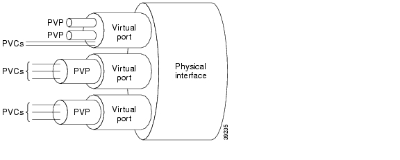
Adding connections to a virtual port for a BXM card does not require the virtual port number. The slot, port, and VPI map to the supporting virtual port. In addition, Vc QDepth is configurable for all connection types.
Bundled Connections
A normal connection is a single PVC. A Frame Relay PVC can terminate at either a Frame Relay endpoint or an ATM endpoint.
Connection bundling creates a full mesh of connections between two groups of Frame Relay ports by executing addcon command only once. When you add a bundle between two groups of ports, you create a connection between each port of one group of ports and each port of the other group of ports. Each group of Frame Relay ports can include up to four ports. Consequently, the maximum number of connections in a bundle is 16 (resulting from a full mesh of connections between two groups of four ports each).
Note that a Port Concentrator Shelf does not support bundling.
Characteristics of connection bundling are:
•
•
•
•
•
When you create a connection bundle with addcon, you do not explicitly specify the required DLCI at each endpoint of each connection. Instead, the DLCIs are automatically assigned using global addressing with the Port IDs, which have been previously assigned to the ports. Consequently, you must first assign a Port ID (other than 0) to every port to which you plan to assign a connection bundle. Use cnfport to assign a Port ID or dspport to see an existing Port ID.
For example, the command
addcon 6.1x3 alpha 7.2x3 1
defines a single connection bundle between a local group of 3 ports (ports 1, 2, and 3 on card 6) and a remote group of 2 ports (ports 2 and 3 on card 7). The resulting connection bundle consists of these six connections:
local node slot 6.port 1 to node alpha slot 7.port 2
local node slot 6.port 1 to node alpha slot 7.port 3
local node slot 6.port 2 to node alpha slot 7.port 2
local node slot 6.port 2 to node alpha slot 7.port 3
local node slot 6.port 3 to node alpha slot 7.port 2
local node slot 6.port 3 to node alpha slot 7.port 3
Each connection in the bundle is assigned the parameters of the same Frame Relay class (class 1, in the example above). Notice that no DLCIs were specified for the six connections. The DLCIs are automatically assigned using the Port IDs of the ports.
As an example, assume that the following Port IDs had been previously assigned for the five ports.
port 6.1Port ID = 22
port 6.1Port ID = 534
port 6.3Port ID = 487
port 7.2Port ID = 92
port 7.3Port ID = 796
As a result of the addcon command, the six connections that you create are automatically assigned DLCIs using global addressing as follows.
6.1.92 - 7.2.22
6.1.796 - 7.3.22
6.2.92 - 7.2.534
6.2.796 - 7.3.534
6.3.92 - 7.2.487
6.3.796 - 7.3.487
The dspcons display shows the entire bundle as a single item. Therefore, you cannot see the automatically assigned DLCIs on the dspcons screen. (The automatically assigned DLCIs in the preceding list appear in italics.) To see the DLCIs, use dspcon, as in the following example:
dspcon 6.1x3 alpha 7.2x3
The preceding shows one screen for the whole bundle then an additional screen for each connection in the bundle. The assigned DLCIs appear in these individual connection display screens.
Note
Note also that you do not enter the coding parameter shown on the Help line.Frame Forwarding Connections
A non-Frame Relay data connection (such as HDLC or SDLC) that is routed through Frame Relay cards can bypass a router or take advantage of DFM at higher data rates. The format slot.port.* identifies a frame forwarding connection. For example:
addcon 11.2.* alpha 12.3.* 2
The "*" indicates to the node that a DLCI is meaningless.
Maximum Connections Per Port with Signaling Protocols
For any Frame Relay card set that has a maximum frame length of 4510 bytes, the use and type of signaling protocol you may have (optionally) specified with the cnfport command results in a limit on the possible number of connections per physical or logical port. The maximum number of connections per port for each protocol is:
•
•
•
The addcon command does not prevent you from adding more than the maximum number connections on a port. If the number of connections is exceeded, the particular LMI does not work on the port, the full status messages that result are discarded, and LMI timeouts occur on the port. A port failure results and subsequently leads to A-bit failures in segments of the connection path.
Syntax
addcon <local_channel> <remote_node> <remote_channel> [con_type] <frame_relay_class | [individual parameters]> [route_avoid]
Parameters
Attributes
Related Commands
delcon, dncon, dspcon, dspcons, upcon
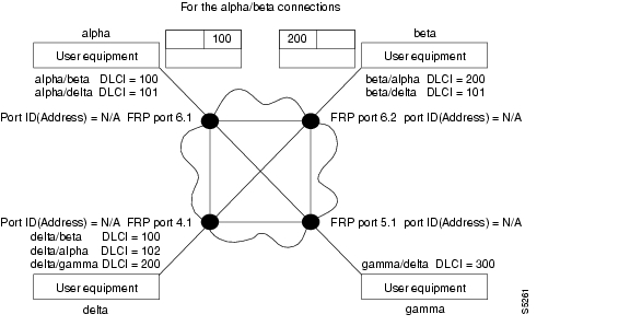
Example (local addressing)
Execute these commands at node Alpha to configure the network shown in Figure 3-1.
addcon 6.1.100 beta 6.2.200 3
addcon 6.1 101 delta 4.1.102 2
addcon 4.1.100 beta 6.2.101 4
addcon 4.1.200 gamma 5.1.300 1
Figure 3-1 Local Addressing Example
Example
Add a connection between the user-device at alpha port 9.1 and the user-device at gamma port 8.1. The user-device at alpha refers to the connection using local DLCI 200. The user-device at gamma refers to this connection using local DLCI 300. The DLCIs have only local significance, so a DLCI must apply to only one connection.
addcon 9.1.200 gamma 8.1.300 1
alpha TRM YourID:1 IGX 8420 9.3 Apr. 13 2000 10:12 PSTLocal Remote Remote RouteChannel NodeName Channel State Type Compression Code Avoid CoS O5.1 beta 25.1 Ok 256 7/8 0 L9.1.100 gamma 8.1.200 Ok fr 0 L9.1.200 gamma 8.1.300 Ok fr 0 L9.2.400 beta 19.2.302 Ok fr 0 L14.1 gamma 15.1 Ok v 0 LLast Command: addcon 9.1.200 gamma 8.1.300 1Next Command:Example
Add another connection at local port 9.1. A DLCI of 100 is used at the local node. A DLCI of 300 can be used at both beta gamma because the DLCIs have only local significance.
addcon 9.1.100 beta 6.2.300 2
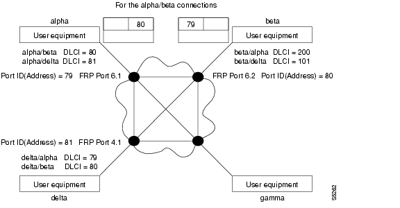
Example (global addressing)
The network to configure in this example is shown in Figure 3-2.
addcon 6.1.80 beta 9.2.79 2
addcon 6.1.81 gamma 4.1.79 1
addcon 4.1.80 beta 6.2.81 5Figure 3-2 Global Addressing Example
Example (bundle connections)
Add a bundle of connections between Frame Relay ports 8.1-3 on node gamma and 19.2-4 on node alpha. For this bundle, the network routes traffic between gamma port 8.2 and alpha port 19.2.
addcon 8.1x3 alpha 19.2x4 1
pubsigx3 VT SuperUser IGX 8410 9.3 Apr. 13 2000 19:41 GMTLocal Remote RemoteChannel NodeName Channel State Type Compress Code CoS8.1x3 alpha 19.2x4 Ok frThis Command: addcon 8.1x3 alpha 19.2x4 1Add these connections (y/n)?Example (frame forwarding)
Add a frame forwarding connection between the local node's port 8.2 and 19.2 on node alpha.
addcon 8.2.* alpha 19.2.* 1
Locals Remote Remote RouteChannel NodeName Channel State Type Compression Code Avoid CoS O6.1 beta 25.2 Ok 256 7/8 0 R8.1.200 alpha 9.1.100 Ok fr 0 R8.2.300 beta 19.1.101 Ok fr 0 R15.1 alpha 14.1 Ok v 0 RThis Command: addcon 8.2.* alpha 19.2.* 1Add these connections (y/n)?Example (modifying bandwidth)
Parameters specified by Frame Relay class 7 for this connection are modified by substituting 30 for Cmax in both directions, enabling ForeSight, and reducing percent utilization from 100 percent to 80 percent.
addcon 8.3.101 beta 19.3.201 7 * * * * 30/30 * * Y 80/80
gamma TRM YourID:1 IGX 8410 9.3 Apr. 13 2000 12:10 CSTLocal Remote Remote RouteChannel NodeName Channel State Type Compression Code Avoid CoS O6.1 beta 25.2 Ok 256 7/8 0 R8.1.200 alpha 9.1.100 Ok fr 0 R8.2.300 beta 19.1.101 Ok fr 0 R15.1 alpha 14.1 Ok v 0 RLast Command: dspconsNext Command: addcon 8.3.101 beta 19.3.201 7 * * * * 30/30 * * Y 80/80addcon (add an ATM connection)
Establishes an ATM connection between the current node another node in the network. ATM connections are added to UNI or NNI ports on ASI or BXM interface cards in a BPX node and UXM or URM interface cards in an IGX node. Before a connection is added, you are prompted to confirm the connection addition. After addcon executes, the system software automatically routes the connection.
The addcon command for ATM adds any one of the following types of ATM connections:
•
•
•
•
•
•
•
•
•
•
•
Frame Relay-to-ATM Interworking enables Frame Relay traffic to be connected across high-speed ATM trunks using ATM standard Network and Service Interworking. Two types of Frame Relay-to-ATM interworking are supported, Network Interworking and Service Interworking.
You can add connections to a virtual port on a BXM card. When adding a connection to a virtual port, the virtual port number is not required. The slot, port, and VPI will map to the supporting virtual port. In addition, Vc QDepth is configurable for all connection types.
The node on which addcon executes is the "owner" of the connection. Automatic rerouting and preferred routing information is entered on the node that owns the connection. See the cnfpref and cnfcos descriptions for details on automatic rerouting.
If addcon is attempted on a port with F4-F5 mapping enabled, and there are no channels left for F4-F5 mapping, the following message is displayed: "No channel left for F4-F5 mapping on this portgroup." If channel unavailability occurs at the remote end, the following message is displayed: "No channel left for F4-F5 mapping on this portgroup at the remote end."
For detailed descriptions of the connection types, traffic classes, policing, and ATM-related topics, refer to the Cisco BPX 8600 Series Installation and Configuration guide or the ATM Forum specifications.
Syntax
addcon <local_channel> <remote_node> <remote_channel> [connection_class] [individual parameters]
Parameters
The addcon parameter prompts depend on the connection type. The following two tables define the parameters and list the defaults and ranges for each parameter.
The notation (0), (1), or (0+1) appears for some parameters. This refers to the state of the Cell Loss Priority (CLP) bit. The usage of the CLP bit is in the traffic policing schemes: (0+1) means cells with CLP=0 or 1; (0) means cells with CLP=0; (1) means cells with CLP=1. The CLP bit is used in different contexts. For example, CDVT (0+1) refers to Cell Delay Variation Tolerance (CDVT) for cells with CLP=0 or 1.
local channel
Specifies the local slot, port, virtual path identifier (VPI), and virtual connection identifier (VCI) for the connection. The format is slot.port.vpi.vci.
You do not need to specify the virtual port (if one has been activated for this channel). The slot, port, and VPI will automatically map to the correct virtual port.
The VPI range for a UNI connection is 1-255. The VPI range for an NNI connection is 1-4095.
When adding an MGX 8850 interface shelf with a UNI interface to a BPX routing node, the VPI range is 1-255. The VCI range is 1-65535.
When adding an MGX 8850 interface shelf with an NNI interface to a BPX routing node, the VPI range is 1-255. The VCI range is 1-65535.
When adding an SES (Service Expansion Shelf) to an IGX 8400 routing node, for VCC addressing, the VPI range is 1-255. The VCI range is 1-65535.
For VPC addressing, when adding an SES interface shelf to an IGX 8400 routing hub with a UNI interface, the VPI range is 1-255. The VCI range is 1-65535.
For VPC addressing, when adding an SES shelf to an IGX 8400 routing with an NNI interface, the VPI range is 1-4095. The VCI range is 1-65535.
Note that when adding an SES to an IGX 8400 routing node, the VPI/VCI configured on the IGX 8400 routing hub should match the VPI/VCI configured on the SES interface shelf endpoint address.
When adding a VP tunnelling DAX connection to an IGX UXM card, either end of the connection can be the VPI or VCI side. This connection type can be any of the ATM connection types supported by UXM virtual trunks, for example, ABR, CBR, UBR, and VBR.
The VCI range is 1-65535. The VCI can be an asterisk (*) to indicate the connection is a virtual path connection (so the VCI has no meaning within the network).
Note
remote node name
Specifies the name of the node at the other (or remote) end of the connection.
remote channel
Specifies the remote node's slot, port, VPI, and VCI for this connection. The format is slot.port.vpi.vci. The VPI and VCI ranges are:
The VPI range for a UNI connection is 1-255. The VPI range for an NNI connection is 1-4095.
The range for a VCI is 1-65535. The VCI can be an asterisk (*) to indicate the connection is a virtual path (the VCI does not provide a distinction within the network).
Note
You do not need to specify the virtual port (if one has been activated for this channel). The slot, port, and VPI will automatically map to the correct virtual port.
connection class/
traffic typeSpecifies one of the following traffic types—VBR (rt-VBR or nrt-VBR), UBR, CBR, ATFST, ATFR, ABRSTD, ABRFST, ATFT, ATFX, ATFTFST, or ATFXFST; or connection classes—for example, for rt-VBR, connection class 3 for a new node running Release 9.2.20.
The subsequent displayed parameters depend on the connection type you choose. To see the parameters associated with each connection type, refer to the appropriate flow diagrams in the Cisco BPX 8600 Series Installation and Configuration guide.
Instead of entering a class of service, you can choose a class number. The class number represents a preconfigured template for a connection type. The class serves as an alternative to specifying each parameter for a connection type. For example, class 4 for nrt-VBR, and class 3 for rt-VBR. To specify a connection class, enter a digit in the range 1-10. To see the parameter values for a class, use the dspcls/dspatmcls commands. To customize any class template, use the cnfcls/cnfatmcls commands.
Note
Note
PCR
Peak Cell Rate: the cell rate that the source cannot exceed.
%Util
Specifies the percentage of bandwidth utilization.
MCR
Minimum Cell Rate: the committed, minimum cell rate for a connection in a network.
CDVT
Cell Delay Variation Tolerance: controls policing tolerance for cells which are early or late relative to the PCR.
FBTC (AAL5 Frame-based Traffic Control)
Enables the possibility of discarding the whole frame, not just one non-compliant cell. This is used to set the Early Packet Discard bit at every node along a connection.
With the ASI, FBTC means packet discard on both policing and queueing. With the BXM, FBTC means packet discard on queueing only.
VSVD
Virtual Source Virtual Destination.
Flow Control External Segments
Enables Cisco WAN switches to perform flow control on external segments (on the CPE, for example) in addition to the Cisco WAN Switching segments.
SCR
Sustainable Cell Rate: the long-term limit on the rate that a connection can sustain.
MBS
Maximum Burst Size: the maximum number of cells that can burst at the PCR and still be compliant. MBS is used to determine the Burst Tolerance (BT), which controls the time period over which the SCR is policed.
Policing
Selects the type of policing to be applied to this connection. Possible values are 1-5. See Table 3-15 for details about each of the five policing modes.
VC QDepth
The depth of the queue VC QDepth. As of Release 9.3, VC QDepth can be configured for all connections, not just ABR connections.
CLP Hi
Cell Loss Priority Hi threshold (% of VC QDepth). When the high threshold is exceeded, the node discards cells with CLP=1 until the number of cells in the queue drops below the level specified by CLP Lo/EPD. As of Release 9.3, CLP Hi can now be configured for all connections, not just ABR connections.
CLP Lo/EPD
Cell Loss Priority Low threshold (% of VC QDepth)/Early Packet Discard. When the number of cells in the queue drops below the level specified by CLP Lo/EPD, the node stops discarding cells with CLP=1.
If the card is a BXM and AAL5 FBTC=yes, the percent of VC QMax equals the value of EPD. Frame-based Traffic Control (FBTC) is FGCRA for AAL5.
For an ASI card, the percent of VC QMax is CLP Lo regardless of the FBTC setting.
As of Release 9.3, CLP Lo/EPD can now be configured for all connections, not just ABR connections.
EFCI
Explicit Forward Congestion Indication threshold (% of VC QDepth).
ICR
Initial Cell Rate: the rate at which a source initially transmits after an idle period.
IBS
Initial Burst Size: the maximum burst size a source can initially transmit after an idle period. IBS applies only to BXM cards.
ADTF
The Allowed-Cell-Rate Decrease Factor.
Time permitted between sending RM cells before the rate is decreased to ICR. (In previous software releases, ADTF was ICR TO—Initial Cell Rate Time Out.)
Trm
An upper bound on the time between forward RM-cells for an active source: an RM cell must be sent at least every Trm milliseconds. (In previous software releases, Trm was Min. Adjust.)
RIF
Rate Increase Factor: controls the amount by which the cell transmission rate may increase upon receipt of an RM cell. (In previous software releases, RIF was Rate Up.)
RDF
Rate Decrease Factor: controls the amount decrease in cell transmission rate when an RM cell arrives. (In previous software releases, RDF was Rate Down.)
Nrm
Nrm.
Maximum number of cells a source may send for each forward RM cell: an RM cell must be sent for every Nrm-1 data cells.
FRTT
Fixed Round Trip Time: the sum of the fixed and propagation delays from the source to a destination and back.
TBE
Transient Buffer Exposure
The negotiated number of cells that the network would like to limit the source to sending during start-up periods, before the first RM-cell returns.
Attributes
Related Commands
delcon, dspcons
Example
Add a standard ABR connection with VSVD and no Default Extended Parameters (which then require user input for SCR, MBS, and so on).
addcon 9.1.100.100 pubsbpx2 9.1.102.102
pubsbpx1 TN SuperUser BPX 15 9.3 Apr. 13 2000 05:22 GMTFrom Remote Remote Route9.1.100.100 NodeName Channel State Type Avoid CoS O9.1.100.100 pubsbpx2 9.1.102.102 Ok abrstd9.1.102.102 pubsbpx2 9.1.100.100 Ok abrstdThis Command: addcon 9.1.100.100 pubsbpx2 9.1.102.102 abr * * * * e e * d * * 1* * * * * * * * *Add these connections (y/n)?Example
Add a virtual path connection (VPC) to virtual circuit connection (VCC) between ports 1 and 2. (This is called a VP tunnelling connection.)
addcon 5.2.10.* pubsigx1p 5.1.1.100 CBR ...
pubsigx1 TN SuperUser IGX 8400 9.3 Apr. 13 2000 05:22 GMTFrom Remote Remote RouteNodeName Channel State Type Avoid CoS O5.2.10.* pubsigx2 5.1.1.100 Ok abrstvp5.1.1.100 pubsigx2 5.2.10.* s Ok abrstvpThis Command: addcon 5.2.10.* pubsigx1p 5.1.1.100 CBR ...Add these connections (y/n)?PCR Values and Traffic Policing
The following three tables provide additional information on PCR values and traffic policing. Table 3-14 defines the minimum PCR values with policing for each card type. Table 3-15 provides traffic policing definitions for each connection type.
addctrlr (add a VSI controller to an IGX node)
Add VSI controller to a UXM line interface. Use the addctrlr command to add an VSI controller to UXM line interface on an IGX node. You can connect a VSI controller to an IGX node by physically connecting a cable from the controller to the UXM line interface.
You cannot connect a VSI controller to these interfaces:
•
•
•
•
The maximum number of controllers that can be added to an IGX is three, although the valid controller ID range is 1 to 16.
Syntax
addctrlr < slot.port> <controller id> <partition id> <control_vpi> <start_vci>
Parameters
Attributes
Related Commands
delctrlr, dspctrlrs
Example
Add controller to port 1 on slot 12, partition ID of 2 and controller ID of 3.
addctrlr 12.1 3 2 0 40
arnold TN Cisco IGX 8430 9.3.10 Aug. 16 2000 17:04 PSTVSI Controller InformationCtrlrId PartId ControlVC Intfc Type CtrlrIPVPI VCIRange3 2 0 40-70 12.1 MPLS 0.0.0.0Last Command: addctrlr 12.1 3 2 0 40Controller added successfully!Next Command:addctrlr (add VSI capabilities to an AAL5 feeder interface (BPX))
Adds VSI capabilities to a trunk interface to which a feeder of type AAL5 is attached. Use the addctrlr command to connect a Private Network-to-Network Interface (PNNI) controller. PNNI controller software resides on the Service Expansion Shelf (SES) hardware.
To add a PNNI controller to a BPX node:
Step 1
Step 2
Note that you can add a PNNI controller to a trunk interface only if the interface already has an active VSI partition corresponding to the partition that is controlled by the PNNI controller. For example, if a PNNI controller controlling partition 1 were added to a trunk interface 12.1. Then it would be necessary that a VSI partition corresponding to partition 1 be active on the interface 12.1. Otherwise the addctrlr command would fail.
When adding VSI controller capabilities to an AAL5 interface shelf (or feeder), the switch software prompts you for the specifics of the VSI controller:
•
•
•
•
The PNNI controller controls VSI partitions on those BXM cards that support VSI capability. Hence a separate VSI control channel must be set up from the PNNI control to each BXM card that supports VSI.
Example: You specify a VPI value of 0 and start_VCI value of 40 for the VSI control channels. Then the control channel corresponding to any BXM card on slot 1 would use VPI, start_VCI values <0, 40>. The VSI control channels to other slots would use the VPI, start_VCI values of <0, 40+slot-1>, where "slot" corresponds to the slot number of the BXM card.
Caution
The addition of a controller to a node will fail if there are not enough channels available to set up the control VCs in one or more of the BXM slaves.
Syntax
addctrlr < slot.port> <controller id> <partition id> <control_vpi> <start_vci>
Parameters
Attributes
Related Commands
addshelf, delctrlr, dspctrlrs
Example
Add controller to port 4 on slot 10, partition ID of 2, and controller ID of 3.
addctrlr 10.4 3 2 0 40
night TN StrataCom BPX 8600 9.3.10 Aug. 1 2000 14:31 GMTBPX 8620 VSI controller informationCtrl Id Part Id Control_VC Trunk Ctrlr Type IntfcVPI VCIRange1 1 0 40-54 10.3 VSI VSI2 2 0 40-54 11.1 VSI VSIWarning partition already in use do you want to add redundant controllerLast Command: addctrlr 10.4 3 2 0 40Next Command:Example
Adds a controller, such a PNNI controller, to a BPX interface shelf.
addctrlr 10.3 3 1 0 40
night TN StrataCom BPX 8600 9.3.10 Aug. 1 2000 14:31 GMTBPX 8620 VSI controller informationCtrl Id Part Id Control_VC Trunk Ctrlr Type IntfcVPI VCIRange1 1 0 40-54 10.3 VSI VSI2 2 0 40-54 11.1 VSI VSIWarning partition already in use do you want to add redundant controllerLast Command: addctrlr 10.3 3 1 0 40Next Command:addextlp (add external loop)
Places an external device in loopback mode. The addextlp command applies to existing connections on an SDP, HDM, LDP, or LDM. A near loopback causes the NEAR EIA template to be applied. A far loopback causes the FAR EIA template to be applied to the data port. The loopback remains in place until removed by the dellp command.
The dspcons command shows which connections are in loopback mode. Specifying an "n" after the channel indicates a near loopback, and an "f" indicates a far loopback. Because addextlp takes the specified connections out of service, use it only when a service disruption is tolerable.
Syntax
addextlp <channel> < n | f >
Parameters
Attributes
Related Commands
dellp, dspcons
Example
Place the device connected to channel 5.1 in near loopback.
addextlp 5.1 n
alpha TRM YourID:1 IGX 8420 9.3 Apr. 13 2000 12:53 PSTLocal Remote Remote RouteChannel NodeName Channel State Type Compression Code Avoid CoS ON5.1 beta 25.1 Ok 256 7/8 0 L9.1.100 gamma 8.1.200 Ok fr 0 L9.2.400 beta 19.2.302 Ok fr 0 L14.1 gamma 15.1 Ok v 0 LLast Command: addextlp 5.1 nNext Command:addjob (add a job)
Creates a job or command script. When you create a new job by using addjob, your privilege level becomes the privilege level of the job itself. When adding commands to the job, you cannot add a command that requires a privilege higher than your privilege level. Furthermore, you must have a privilege level at least as high as the job to run the job (with runjob, for example).
The system does not check the validity of the command with respect to the current state of the network or for relationships to other commands in the job. To ensure that it works as expected, try running the job with runjob.
Syntax
addjob [description] [execution time, execution interval] <commands>
Parameters
Attributes
Related Commands
deljob, dspjob, dspjobs, editjob, prtjob, runjob, stopjob
Example
The system response is a series of prompts requesting details of the job. The system requests a job description (or name), an execution time for the job, a unit for the interval at which the job is to run (hours, for example), the number of units in the interval, the commands to execute, and what to do with the result.
addjob
alpha TRM YourID:1 IGX 8420 9.3 Apr. 13 2000 14:15 PSTJob 1 testLast Execution Results: None Status: IdleNext Execution Time: 08/17/97 20:20:30 Interval: 1 days1: prtlog- Failure Reaction: Repeat 2 Times and Abort Exec. Results: NoneLast Command: addjobNext Command:In this example, a new job is being created. The job number is "1." The job description (or name) is "test." The job is scheduled to run on August 17, at 2:20:30 PM and every day thereafter at the same time. The command in the job is prtlog. If this command fails when the job runs, it tries twice again and aborts if unsuccessful.
The "Enter Cmd" prompt at the bottom of the screen indicates you can enter the next command for the job. To exit addjob, press Return without entering a command.
addjobtrig (add job trigger)
Configures a job to run if a failure or repair occurs on a trunk (narrowband or broadband), a line (voice, data, Frame Relay, ATM, narrowband, broadband), or a T3 (DS3). You can also use addjobtrig to allocate or release bandwidth from other connections. This bandwidth decision depends on whether the EIA lead status is "up" or "down." For example, a job can be triggered to run if the RTS lead of an HDM/LDM port changes state. If the FRM you are using is an FRM-T1 or E1, it qualifies as a line and can be used as a job trigger.
A line failure is any alarm condition that takes the trunk or line out of service. Such a condition is always a major alarm. However, not all major alarms cause the trunk or line to be considered failed. Those that are considered failed are the ones that appear on the dsptrks or dsplns screens with a color associated with it, such as "Major—Local All Ones" or "Major—Remove Packet Out of Frame (Yel)". Specifically excluded are all the statistical alarms, some of which may be major.
A line repair is the opposite of a line failure. A repair of a line occurs when the alarms on the line are removed.
The lead type on HDM/LDM is based on the configuration from cnfleadmon. The display shows: "Front Card Supports Lead State Trap".
Syntax
addjobtrig <job_number> <line_type> <line_specifier> <fail/repair>
Parameters
Attributes
Related Commands
addjob, dspjob, dspjobs
Examples
Example
Trigger job 1 whenever a repair of line 14 occurs.
addjobtrig 1 c 14 r
alpha TRM YourID:1 IGX 8420 9.3 Apr. 13 2000 14:22 PSTJob Description Next Execution Status Interval Access Group1 test 08/17/97 11:00:00 Idle 1 days Group 1Trigger 1 - CLN 14 REPAIRLast Command: addjobtrig 1 c 14 rNext Command:addlnloclp (add local loopback to line)
Establishes a local-remote loopback on a trunk or port card in a BPX. Applicable cards are the ASI, BNI, BME, and BXM.
While a line loop is present, software suspends the card self-test and the line diagnostic test that normally run when a line goes into alarm. Suspending these tests prevents background test loops from interfering with the user-specified loop.
Line loops are set for a line on the local node, so you cannot specify a remote node, and no network messaging is supported for setting a line loop of any type on a remote node.
Line loop status is displayed on the dsplns screen for an ASI, BME, or a BXM in port mode and the dsptrks screen for a BNI, BME, or a BXM in trunk mode. Line loop status is not displayed for connections (dspcons) affected by a line loop. Instead, a warning is printed if the line has connection traffic travelling on it, and an event is logged when a line loop is set or cleared. A line loop on a trunk generates Comm Fail, causing connections to fail and be rerouted.
For both of the dsplns and dsptrks screens, the "[" character appears before the back card type in the "Type" column to indicate that the line local loopback is active.
The line loop state is not saved in BRAM or on a rebuild but is preserved on a switchover. After a rebuild, a line's loop state is cleared.
Exercise caution when you set up loops on a BNI, BME, or BXM trunk because looping an added BNI/BXM/BME trunk causes Comm Failure and connection rerouting. BNI/BXM/BME addlnlocrmtlp is not supported because of a lack of useful purpose, and Cisco recommends that you use addlnloclp only when the trunk is upped but not added. On the other hand, the system does not prevent you from looping an added BNI/BXM/BME trunk port.
Syntax
addlnloclp <slot.port>
Parameters
Attributes
Related Commands
dellnlp, dsptrks, dsplns, addlnlocrmtlp
Example
The dsplns display appears with the connection highlighted and a prompt for confirmation.
addlnloclp 11.8
sw53 VT Cisco BPX 8620 9.3.m0 Dec. 14 2000 12:33 GMTLine Type Current Line Alarm Status11.1 OC3 Clear - OK11.8 ]OC3 Clear - OKLast Command: addlnloclp 11.8addlnlocrmtlp (add local-remote loopback to BPX line)
Establishes a local-remote loopback on a trunk or port card in a BPX. Applicable cards are the ASI, BNI, and BXM/BME.
While a line loop is present, software suspends the card self-test and the line diagnostic test that normally run when a line goes into alarm. Suspending these tests prevents background test loops from interfering with the user-specified loop.
Line loops are set for a line on the local node, so you cannot specify a remote node, and no network messaging is supported for setting a line loop of any type on a remote node.
Line loop status is displayed on the dsplns screen for an ASI or a BXM/BME in port mode and the dsptrks screen for a BNI or a BXM/BME in trunk mode. Line loop status is not displayed for connections (dspcons) affected by a line loop. Instead, a warning is printed if the line has connection traffic travelling on it, and an event is logged when a line loop is set or cleared. A line loop on a trunk generates Comm Fail, causing connections to fail and be rerouted.
For both of the dsplns and dsptrks screens, the "[" character appears before the back card type in the "Type" column to indicate that the line local-remote loopback is active.
The line loop state is not saved in BRAM or on a rebuild but is preserved on a switchover. After a rebuild, a line's loop state is cleared.
Exercise caution when you set up loops on a BNI or BXM/BME trunk because looping an added BNI/BXM/BME trunk causes Comm Failure and connection rerouting. BNI/BXM/BME addlnlocrmtlp is not supported because of a lack of useful purpose, and Cisco recommends that you use addlnloclp only when the trunk is upped but not added. On the other hand, the system does not prevent you from looping an added BNI/BXM/BME trunk port.
In this release, you can use the addloclp and addlocrmtlp commands to enable a two-segment connection at the hub node port endpoint in a network of IGX hubs and MGX 8800 interface shelves. The addloclp and addlocrmtlp commands are blocked at the interface shelf trunk endpoint. The addrmtlp command is not supported at either endpoint of the connection. You can use the dellp command to remove the local (or local remote) loopbacks that have been added; however, you cannot use the dellp command at the trunk endpoint of the connection—it will be blocked. Loops of any kind are not supported for the middle segment of a three-segment connection.
Syntax
addlnlocrmtlp <slot.port>
Parameters
Attributes
Related Commands
dsptrks, dsplns, dellnlp, addlnloclp
Example
The dsptrks screen appears with the loopback highlighted by the "[" character.
addlnlocrmtlp 10.1
pubsbpx1 TN SuperUser BPX 8620 9.3 Apr. 13 2000 01:27 GMTTRK Type Current Line Alarm Status Other End1.1 T3 Clear - OK pubsaxi1(AXIS)1.3 T3 Clear - OK pubsipx1/84.1 OC-3 Clear - OK -10.1 [OC-3 Clear - OK -Last Command: addlnlocrmtlp 10.1Next Command:addloclp (add local loopback to connections on a port)
Places these types of channels in local loopback mode:
•
•
•
•
•
•
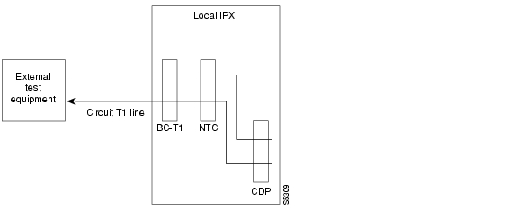
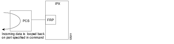
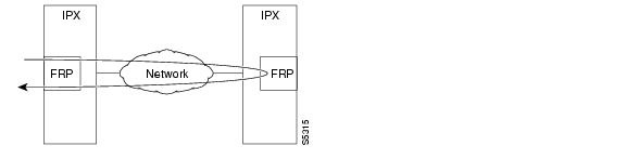
For voice connections, addloclp creates a signal path from a channel or group of channels on an incoming line then back out to the line. External test equipment can test the integrity of the path at the T1 DS0 level. Figure 3-3 shows a local loopback on a voice channel.
Figure 3-3 Local Loopback on a Voice Channel
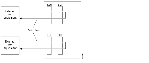
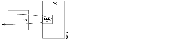
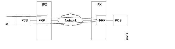
For data connections, addloclp creates a signal path from the incoming data port or set of ports back to these same port(s) through the local CDP/CVM, SDP/HDM, or LDP/LDM. External test equipment can then test the integrity of the path. Figure 3-4 illustrates a local loopback on a data connection.
Figure 3-4 Local Loopback on a Data Connection
A local loopback can simultaneously exist at both ends of a connection. However, a local loopback and a remote loopback cannot co-exist on a connection. (See the addrmtlp description for more information.)
Before executing a loopback, the IGX node performs signal and code conditioning to remove the connection from service. The loopback remains in place until removed by the dellp command. Only existing connections can be looped back.
Use the dspcons command to see which connections are looped back. A flashing right parenthesis ")" or left parenthesis "("is used in the connections display to indicate a loopback. The direction and location of the parenthesis depends on whether the loopback is local or remote and which end of the connection was used to establish the loopback.
A local loopback initiated from the local end of the connection looks like this in the connections display:
A local loopback initiated from the remote end of the connection looks like this:
In Frame Relay connection loopback mode (DLCI included in command), all packets from the far-end of the connection are dropped. The far-end system software is informed of the loopback. In port loopback mode (port specified without a DLCI), all packets for this port are dropped and each opposite end is informed of the loopback mode.
Use the format slot.port in port mode to loop just the port. The data is looped directly in the FRI back card, so no data reaches the muxbus or cellbus. Use the format slot.port.DLCI in connection (channel) mode to loop a specific channel. Note that this can affect up to 252 connections (channels) in port loopback mode.
Because the addloclp command causes the connection(s) to be removed from service, you should use loopbacks only when a service disruption can be tolerated. You establish remote loopbacks with the addrmtlp command. You remove local and remote loopbacks with the dellp command. You can also initiate loopbacks for data channels by pressing a button on the front of the associated data card.
Frame Relay Local Loops with Port Concentrator
When a Frame Relay port or connection is located on a Port Concentrator instead of directly on an FRP or FRM card, the data test path is different. When just the <port> parameter is used, incoming data is looped back out on the Port Concentrator port, as shown in Figure 3-5.
Figure 3-5 Local Loop on Port Concentrator
This loop disrupts all Frame Relay connections on the port that is under test.
When you specify a connection with <port.dlci> parameters, the connection is looped back at the FRM-2 or FRP-2 interface with the IGX card bus, as shown in Figure 3-6.
Figure 3-6 Local Loop on FRM-2 or FRP-2
As shown, this test verifies the operation of all components from the Port Concentrator to the IGX interface with the FRP-2 or FRM-2 card.
This tests interrupts only the specified connection on the Port Concentrator port.
In this release, the addloclp and addlocrmtlp commands support the two-segment connection at the hub node port endpoint in a network of IGX hubs and SES interface shelves. The addloclp and addlocrmtlp commands are blocked at the interface shelf trunk endpoint. The addrmtlp command is not supported at either endpoint of the connection. You can use the dellp command to remove the local (or local remote) loopbacks that have been added; however, you cannot use the dellp command at the trunk endpoint of the connection—it will be blocked. Loops of any kind are not supported for the middle segment of a three-segment connection.
Syntax
addloclp channel
Parameters (Voice)
Parameters (Data)
slot
Specifies the slot number of the card containing the port to loop at the local node.
port
Specifies the local port to loop at the local node.
Parameters (Frame Relay Connection)
Parameters (ATM Connection)
Attributes
Related Commands
addrmtlp, dellp, dspcons, dspfrport
Example
The connections screen appears with connection 14.1 highlighted. The system prompts you to confirm the loopback. To confirm it, enter y.
addloclp 14.1
Next Command:alpha TRM YourID:1 IGX 8420 9.3 Apr. 13 2000 11:03 PSTLocal Remote Remote RouteChannel NodeName Channel State Type Compression Code Avoid CoS O5.1 beta )25.1 Ok 256 7/8 0 L9.1.100 gamma 8.1.200 Ok fr 0 L9.1.200 gamma 8.1.300 Ok fr 0 L9.2.400 beta 19.2.302 Ok fr(Grp) 0 L14.1 )gamma 15.1 Ok v 0 LLast Command: addloclp 14.1Next Command:addlocrmtlp (add local-remote loopback in a tiered network)
Adds support of a local-remote loopback for testing multisegment connections in a tiered network. The effect is to instruct the remote node to set up a remote loopback.
You must execute the addlocrmtlp command before using tstcon and tstdelay for multisegment connections. For interface shelves, you can execute addlocrmtlp on either the interface shelf (after you telnet to it).
After testing is complete, remove the local-remote loop by executing dellp. A parenthesis on the screen shows the loop's endpoint.
The addloclp and addlocrmtlp commands support a two-segment connection at the hub node port endpoint in a network of IGX hubs and SES interface shelves. The addloclp and addlocrmtlp commands are blocked at the interface shelf trunk endpoint. The addrmtlp command is not supported at either endpoint of the connection.
You can use the dellp command to remove the local (or local remote) loopbacks that have been added; however, you cannot use the dellp command at the trunk endpoint of the connection—it will be blocked. Loops of any kind are not supported for the middle segment of a three-segment connection.
Syntax
addlocrmtlp <channel(s)>
Parameters
Attributes
Related Commands
tstcon, tstdelay, dellp, dspcons, dspfrport
Example
The connections screen appears with the connection highlighted and prompts you to confirm.
addlocrmtlp 5.1.3.100
pubsbpx1 TN SuperUser BPX 9.3 Apr. 13 2000 14:41 PDTLocal Remote RemoteChannel NodeName Channel State Type Compress Code CoS5.1.3.100 ( pubsbpx3 7.1.2.49 Ok aftr 0This Command: addlocrmtlp 5.1.3.100Loopback these connections (y/n)?addport (add ATM or Frame Relay port)
This command is required to add ports to the IGX and BPX. Use addport to:
•
•
•
•
•
Note
The addport command is required before the ports can be activated (upport). The optional <vport> identifier indicates a virtual port. Only BXM cards support virtual ports.
For BPX only, since Release 9.3.0, upln no longer automatically configures a port. You must use the addport command to add the port before you can use the addcon command. You can verify that the line has been activated by using the dsplns command.
Syntax
addport <slot.port>[.<vport>]
For FRP or FRM card sets:
addfrport <slot.port> [DS0 channel] [56 | 64]For UFM-C card sets:
addfrport <slot.port> <line.DS0_channel>Parameters
Error/Warning Messages
Attributes
Related Commands
delport, upport, dnport, dspports, dspport, cnfport
Example
Add port 3 to the BXM card in slot 11.
addport 11.3
sw53 TN Cisco BPX 8620 9.3.m0 Dec. 19 2000 12:43 GMTPort configuration for ATM 11From VPI Min/Max Bandwidth Interface State Protocol Type11.3 0 / 255 353208 (cps) LM-BXM INACTIVE NONE UNILast Command: addport 11.3256 PVCs allocated. Use 'cnfrsrc' to configure PVCsExample
Add the internal ATM port 11.1 on the Universal Router Module (URM) in an IGX node. The interface type is "INTERNAL". The default configuration is UNI with no protocol and is the same as the default configuration for a UXM port.
addport 11.1
sw190 TRM Cisco IGX 8420 9.3.e9 Oct. 6 2000 05:28 GMTPort configuration for ATM 11Port Chan Speed Interface State Protocol Type1 1 353208 (cps) INTERNAL INACTIVE NONE UNILast Command:addport 11.1256 LCNs allocated. Use 'cnfrsrc' to configure LCNsNext Command:Example
Add a single Frame Relay port that occupies DS0s (timeslots) in the range 9-15. For a T1 line, this channel rate is 7 x 64 Kbps = 448 Kbps, as the screen example shows. The card is an FRP.
addport 21.9 -15
gamma TRM YourID:1 IGX 8410 9.3 Apr. 13 2000 17:28 CSTPort configuration for FRP 21From Chan Speed Interface State 1 9-15 448 FRI T1 INACTIVELast Command: addport 21.9-15Next Command:addrmtlp (add remote loopback to connections)
The addrmtlp command places these types of channels in remote loopback mode:
•
•
•
•
•
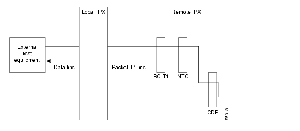
For voice connections, addrmtlp loops the information stream from the designated channel or group of channels on an incoming circuit line across the network and loops it back to the circuit line by way of the remote CDP or CVM. External test equipment can then test the integrity of the path at the T1 DS0 level. Figure 3-7 illustrates a remote loopback on a voice channel.
Figure 3-7 Remote Loopback on a Voice Channel
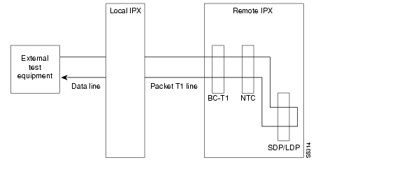
For data connections, addrmtlp transfers the information stream from the designated channels through the network and loops it back to the data port(s) through a remote SDP, HDM, LDM, or LDP. External test equipment can then test the integrity of the path. Figure 3-8 illustrates a data connection remote loopback.
Figure 3-8 Remote Loopback on a Data Connection
Prior to executing the loopback, the IGX node applies signaling template bit patterns to the A, B, C, and D signaling bits at the remote end to remove the connection from service. The loopback remains in place until removed by the dellp command. Only existing connections (those that have been entered with the add-on command) can be looped back. You cannot establish a remote loopback on a connection that is already looped back, either locally or remotely. (See the addloclp command for more information on local loopbacks.)
Use the dspcons command to see which connections are looped back. A flashing left parenthesis "("or right parenthesis ")" is used in the connections display to indicate a loopback. The direction and location of the parenthesis depends on whether the loopback is local or remote and which end of the connection was used to establish the loopback. A remote loopback initiated from the local end of the connection looks like this:
A remote loopback initiated from the remote end of the connection looks like this:
For remote loopback of Frame Relay connections, note that in remote loopback mode, if the transmit minimum bandwidth exceeds the receive minimum bandwidth, then loopback data may be dropped. For this reason, the connection speeds will be checked and the user will receive the following message if there is a problem:
Warning—Receiver's BW < Originator's BW-Data may be droppedBecause the addrmtlp command causes the connection to be removed from service, loopbacks should be used only when a service disruption can be tolerated. Local loopbacks are established with the addloclp command. Both local and remote loopbacks are removed by the dellp command. Loopbacks for data channels can also be initiated by pressing a push-button on the front of the associated data card.
Remote Loopbacks and the Port Concentrator Shelf
For Frame Relay remote loops, DLCI MUST be specified; entering only port number only generates an error message.
Unlike local loopbacks, remote loopbacks are not supported for Frame Relay ports; connections must be specified. Data incoming on the Frame Relay port is looped at the remote end FRM-2 or FRP-2 card, as shown in Figure 3-9.
Figure 3-9 Frame Relay Remote Loops
As shown, this test verifies the operation of IGX network components up to the interface with the remote-end FRM-2 or FRP-2. This test interrupts data traffic for only the connection specified by DLCI.
If a port concentrator is attached to the FRM-2 or FRP-2, the only difference in the loop is that the port specified to loop data is on the Port Concentrator, as shown in Figure 3-10.
Figure 3-10 Frame Relay Remote Loops with Port Concentrator
The addloclp and addlocrmtlp commands support the two-segment connection at the hub node port endpoint in a network of IGX hubs and SES interface shelves. The addloclp and addlocrmtlp commands are blocked at the interface shelf trunk endpoint. The addrmtlp command is not supported at either endpoint of the connection. You can use the dellp command to remove the local (or local remote) loopbacks that have been added; however, you cannot use the dellp command at the trunk endpoint of the connection—it will be blocked. Loops of any kind are not supported for the middle segment of a three-segment connection.
Syntax
addrmtlp (see parameter tables)
Parameters (Voice)
Parameters (Data)
slot
Specifies the slot number of the card containing the port to loop at the local node.
port
Specifies the local port to loop at the local node.
Parameters (Frame Relay)
Parameters (ATM)
Related Commands
addloclp, dellp, dspcons
Attributes
Related Commands
addloclp, dellp, dspcons
Example
The connections screen appears with connection 5.1 highlighted. The system prompts to confirm the loopback. To confirm it, enter y. A flashing parenthesis ")" appears in the "Remote Channel" column of the connection to indicate that the connection is looped back.
addrmtlp 5.1
alpha TRM YourID:1 IGX 8420 9.3 Apr. 13 2000 12:57 PSTLocal Remote Remote RouteChannel NodeName Channel State Type Compression Code Avoid CoS O5.1 beta )25.1 Ok 256 7/8 0 L9.1.100 gamma 8.1.200 Ok fr 0 L9.2.400 beta 19.2.302 Ok fr 0 L14.1 gamma 15.1 Ok v 0 LLast Command: addrmtlp 5.1Next Command:addshelf (add interface shelf or controller to a routing node or hub)
In a tiered network, adds an ATM link between:
•
•
•
An MPLS controller is considered an interface shelf from the BPX's perspective.
The interface shelf can be one of these:
•
•
•
•
•
•
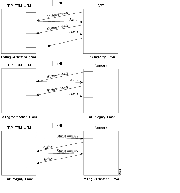
The signaling protocol that applies to the trunk on an interface shelf is Annex G. (Annex G is a bidirectional protocol defined in Recommendation Q.2931, used to monitor the status of connections across an UNI interface. The Annex G protocol is used in this release to pass connection status information between an IGX/BPX core switch shelf and an attached feeder.)
For example, the MGX 8850 interface shelf, or feeder, communicates over a UXM/UXM-E interface with the routing hub over Annex G LMI using AAL5 format.
Note
Each IGX/AF, MGX 8220, MGX 8850, or SES shelf has one trunk that connects to the BPX or IGX node serving as an access hub. A BPX routing hub can support up to 16 T3 trunks to the interface shelves, which can be IGX/AF, MGX 8220, or MGX 8850 interface shelves. An IGX hub can support up to four trunks to the interface shelves, which can be IGX/AF or SES (Service Expansion Shelf) shelves.
Before it can carry traffic, you must "up" the trunk on an interface shelf (using uptrk on both the interface shelf and the IGX/BPX core switch shelf) and "add" it to the network (using addshelf). Also, a trunk must be free of major alarms before you can add it with the addshelf command.
Use the commands addshelf and addctrlr to add an MPLS or PNNI controller to the BPX. Use the command addshelf with option "v" to add a VSI shelf. This is used mainly for MPLS controllers. Use the command addctrlr to add a controller to a shelf that has LMI capabilities.
You can use an IGX as a feeder node to connect via a UXM IMA trunk to an IGX or BPX router node using IMATM. Use addshelf with the "I" option at the IGX node to add the feeder trunk connecting it to an IGX feeder node.
Syntax
Interface shelf:
addshelf <slot.port> <shelf-type> [vpi] [vci]
addshelf <slot>.<primary link> <shelf type>Label switch controller:
addshelf <slot.port> <device-type> <control partition> <control ID>
VSI controller:
addshelf <trunk slot.port> v <ctrlr id> <part id> <control vpi> <control vci start> <redundant ctrlr warning>
Note
Parameters
Attributes
Related Commands
delshelf, dspnode, dsptrks
Release History
Previous to Release 9.2, WAN switching software supported the ability to configure the MGX 8220 as an interface shelf to the BPX. Release 9.1 introduced the ability for the MGX 8850 to serve as an interface shelf to a BPX routing hub. Release 9.2 introduced the ability for an SES (Service Expansion Shelf) to serve as an interface shelf to an IGX 8400 routing hub.
Release 9.2.20 supports:
•
•
•
Signaling Channel Used by MGX 8850 and SES Interface Shelves Connecting to Routing Hubs
The SES interface shelf with a UXM/UXM-E interface communicates with the routing hub over an Annex G LMI interface by using AAL5 format.
Annex G is a bidirectional protocol used to monitor the status of connections across a UNI interface. This includes the real-time notification of the addition or deletion of connection segments and the ability to pass the availability (active state) or unavailability (inactive state) of the connections crossing this interface.
An SES feeder uses the Annex G protocol to pass connection status information between itself and an IGX 8400 routing hub. Similarly, an MGX 8850 feeder uses the Annex G signaling channel to pass connection status information between itself and a BPX routing hub.
The SES interface shelf communicates with an IGX routing hub through ATM cells. Thus, IP data destined for an IGX 8400 is encapsulated in an AAL5 ATM cell format.
addshelf Error Messages
Some of the possible error messages for the addshelf command:
•
•
•
•
•
•
•
•
•
•
•
•
•
•
•
•
Example (Interface Shelf)
Add an MGX 8220 at trunk 11.1. After you add the shelf, the screen displays a confirmation message and the name of the shelf. Add the MGX 8220 (may be referred to on screen as AXIS):
addshelf 11.1 a
The sample display shows a partially executed command prompting you for the interface shelf type:
nmsbpx23 TN SuperUser BPX 8620 9.3.10 Apr. 4 2000 13:28 PSTBPX Interface Shelf InformationTrunk Name Type Alarm1.3 AXIS240 AXIS OK11.2 A242 AXIS OKThis Command: addshelf 11.1 aEnter Interface Shelf Type: I (IGX/AF), A (AXIS), P (APS), V (VSI), X (AAL5)Next Command:Example (MGX 8850 AAL5 Interface Shelf)
Add an MGX 8850 at trunk 4.8. After you add the MGX 8800 shelf, the screen displays a confirmation message and the name of the shelf.
To add the MGX 8850 (may be referred to on screen as AAL5), use this command:
addshelf 4.8 x
The system response shows that an MGX 8850 was added on trunk 4.8 as an AAL5 (ATM Adaptive Layer 5) type of interface shelf. (Adding an MGX 8850 interface shelf is similar to adding an MPLS controller interface shelf.)
pswbpx3 TN SuperUser BPX 8600 9.3.10 June 6 2000 13:28 PSTBPX 8620 Interface Shelf InformationTrunk Name Type Part Id Ctrl Id Control_VC AlarmVPI VCIRange4.8 SIMFDR0 AAL/5 - - - - OKThis Command: addshelf 4.8 xEnter Interface Shelf Type: I (IGX/AF), A (AXIS), P (APS), V (VSI), X (AAL5)Next Command:Example (SES to an IGX)
Add an SES interface shelf to an IGX 8400 (using a UXM or UXM-E interface). After you add the SES interface shelf, the screen displays a confirmation message and the name of the shelf. Add the SES (may be referred to on-screen as AAL5) as follows:
addshelf 6.1 X
Enter Interface Shelf Type: X (AAL5)
Note
sw288 TN SuperUser IGX 8420 9.3 Apr. 13 2000 15:38 PSTTRK Type Type Alarm9.1 ases1 AAL5 MINThis Command: addshelf 4.1Enter Interface Shelf Type: I (IGX), A (AXIS), P (APS), V (VSI), X (AAL5)IGX Interface Shelf InformationTrunk Name Type Alarm9.1 ses_fdr AAL5 MINThis Command: addshelf 4.1 xEnter Interface Shelf Type: A (AXIS), P (APS), V (VSI), X (AAL5)Shelf has been addedNext Command:The sample display shows that an SES was added on trunk 9.1 as an AAL5 type of interface shelf. (AAL5 is the ATM Adaptive Layer 5 protocol, which is an ATM standard interface that is used by the routing node or routing hub to communicate with the SES shelves.) Adding an IGX interface shelf is similar to adding an MPLS (Multiprotocol Label Switching) controller as an interface shelf.
The addshelf command will prompt for "Interface Shelf Type." Because the MGX 8220, MGX 8850, and the SES (Service Expansion Shelf) use the same Annex G LMI signaling protocol to communicate with an IGX routing hub, they all use the same interface shelf type of AAL5 (designated by the addshelf "X" option).
Adding a VSI Controller
The maximum number of controllers that can be attached to a given node is limited by the maximum number of feeders (16) that can be attached to a BPX hub. Therefore, the total number of feeders and controllers cannot exceed 16.
You add a VSI controller, such as an MPLS controller, to a switch by using the addshelf command with the vsi option. The vsi option of the addshelf command identifies VSI controllers and distinguishes them from interface shelves (feeders).
The VSI controllers are allocated a partition of the switch resources. VSI controllers manage their partition through the VSI interface. The controllers run the VSI master. The VSI master entity interacts with the VSI slave running on the BXMs through the VSI interface, to set up VSI connections using the resources in the partition assigned to the controller.
Two controllers that are intended to be used in a redundant configuration must specify the same partition when added to the node through the addshelf command.
When a controller is added to the node, switch software sets up the infrastructure so that the controllers can communicate with the slaves in the node. The VSI entities decide how and when to use these communication channels.
The controllers also require a communication channel between them. This channel could be in-band or out-of-band. When a controller is added to the switch, switch software sends controller information to the slaves. This information is advertised to all the controllers in the partition. The controllers may decide to use this information to set up an intermaster channel. Alternatively the controllers may use an out-of-band channel to communicate.
To add a controller to the node, use the addshelf command. You add a redundant controller in the normal way, except that it specifies a partition that may be already in use by another controller. The addshelf command allows for up to three controllers to manage the same partition.
One of the parameters that must be specified with the addshelf command when a VSI controller is added to the switch is the controller ID. This is a number between 1 and 32 that uniquely identifies the controller. Two different controllers must always have different controller IDs.
The management of resources on the VSI slaves requires that each slave in the node has a communication control VC to each of the controllers attached to the node. When a controller is added to the BCC via the addshelf command, the BCC sets up the set of master-slave connections between the new controller port and each of the active slaves in the switch. You specify the master-slave connections by using the <Control VPI> and <Control Start VCI> parameters. The default for these parameters is 0/0.
Note
Feature Mismatching to Verify VSI Support
The cnfrsrc and addshelf commands, in addition to other configuration commands, perform mismatch verification on the BXM and UXM cards. For example, the cnfrsrc and addshelf commands verify whether the cards both have VSI 2.0 support configured.
The Feature Mismatching capability does not check mismatched cards unless the actual feature has been enabled on the card. This allows for a graceful card migration from an older release.
Example (Redundant VSI Controller)
Add a redundant (more than one) VSI controller (as an interface shelf to a BPX node), on slot 11 on port 1, with a control partition of 1 and control ID of 2.
addshelf 11.1 vsi 1 2
night TN StrataCom BPX 8600 9.3 Apr. 13 2000 14:31 GMTBPX Interface Shelf InformationTrunk Name Type Part Id Ctrl Id Alarm1.1 sww222 IGX/AF - - UNRCH10.3 VSI VSI 1 1 OKWarning partition already in use do you want to add redundant controller?Last Command: addshelf 11.1 vsi 1 2Adding an MPLS Controller
For MPLS to carry traffic, you must first up the link to an MPLS controller (by using uptrk) at the BPX node. You can then add the link to the network (by using addshelf).
The link must be free of major alarms before you can add it with the addshelf command.
Note
Example (MPLS Controller)
Add trunk 4.1 as a VSI-MPLS controller interface shelf with control ID set to 1, partition ID set to 1,
control VC VPI set to 0, and control VC VCI start at 40.
addshelf 4.1 vsi 1 1 0 40
nmsbpx23 TN SuperUser BPX 15 9.3.10 Aug. 1 2000 13:28 PSTBPX 8620 Interface Shelf InformationTrunk Name Type Part Id Ctrl Id Control_VC AlarmVPI VCIRange4.8 SIMFDR0 AAL/5 - - - - OK4.1 VSI VSI 1 1 0 40-54 OKThis Command: addshelf 4.1 v 1 1 0 40Next Command:addtrk (add a trunk between nodes)
You must add a trunk to the network before it can carry traffic. You need only to execute addtrk at one of the nodes terminating the trunk. Before you add a trunk to the network, you must have activated (or "upped") the trunk at both ends by using uptrk.
A trunk must be free of major alarms before you can add it. If you use addtrk to join two networks that were previously separate, the local node verifies that all node names and node numbers in both networks are unique before it adds the trunk.
You cannot add a trunk while any of these conditions are true:
•
•
•
•
•
•
Warning
Adding a Virtual Trunk
You can add a trunk as a physical trunk or a virtual trunk. A virtual trunk is a way to connect Cisco nodes through a public ATM cloud. You can define virtual trunks on BNI, BXM and UXM cards.
(Note that even though nodes running Release 9.2 can interoperate with 9.1 or 8.5 nodes, if you are running a network with mixed releases, you cannot add UXM and BXM virtual trunks because the networking messages are incompatible due to the virtual trunk number and different cell format on virtual trunks. BNI cards use STI cell format, and BXM and UXM cards use NNI cell format.)
To designate a trunk as a virtual trunk, you use a virtual trunk number, which is used to differentiate the virtual trunks within a physical port. (Refer to the BPX 8600 Series Reference for more information on virtual trunking.)
For the BXM card, you can define a maximum of 32 virtual trunks within one port. Valid virtual trunk numbers are 1-31 per port. The number of virtual trunks available is limited by the number of virtual interfaces (VIs) available on the card. Each logical trunk (physical or virtual) consumes on VI.
For the UXM card, you can define a maximum of 16 virtual trunks within one port. Valid virtual trunk numbers are 1-15.
The addtrk command will be blocked for virtual trunks configured for VSI.
Syntax
addtrk <slot.port>[.vtrk]
Parameters
Attributes
Related Commands
deltrk, dsptrks, uptrk
Example
Add trunk 5.4 to node sw180.
addtrk 5.4
NOTE: update example to show: "Add trunk 5.4 to node sw180."sw180 TN Cisco IGX 8420 9.3.r3 Dec. 19 2000 14:10 GMTTRK Type Current Line Alarm Status Other End5.4 OC3 Clear - OK -8 T1/24 Clear - OK sw108/14Last Command: addtrk 5.4addtrkred (add trunk redundancy)
Configures trunk redundancy on an ATM trunk. The addtrkred command specifies a backup trunk to the primary trunk. Applicable line types are T3 and E3. The redundancy scheme requires two sets of ATM trunk cards and two standard T3 or E3 cables (not Y-cables). Note the following characteristics of trunk redundancy:
•
•
•
•
•
Syntax
addtrkred <primary trunk> <secondary trunk>
Parameters
primary trunk
Specifies the slot number of the primary trunk card set.
secondary trunk
Specifies the slot number of the secondary trunk card set as backup.
Attributes
Related Commands
deltrkred, dsptrkred
Example
Add bandwidth redundancy for the primary ATM trunk in slot 4 with backup from the ATM trunk in slot 5.
addtrkred 4 5
beta TRM YourID:1 IGX 8420 9.3 Apr. 13 2000 15:15 MSTATM Line Backup ATM Line4 5Last Command: addtrkred 4 5Next Command:adduser (add a user)
Adds a user to the network. The first time the new user ID is used for logon, a prompt asks the user to change from the default password to a new password which they enter using the cnfpwd command. Users with privilege levels 1 through 5 may add users with lower privilege levels. Because privilege level 6 has no user levels below it, level 6 cannot add any users.
Syntax
adduser <user_id> <privilege_level>
Parameters
Attributes
Related Commands
cnfpwd, deluser, dspusers
Example
Add a user sarah with privilege level 5.
adduser sarah 5
alpha TRM YourID:1 IGX 8410 9.3 Apr. 13 2000 13:48 PSTYourID 1Sarah 5Last Command: adduser Sarah 5Next Command:addyred (add Y-cable redundancy)
Enables card redundancy for cards on the BPX and IGX. The addyred command also enables SONET Automatic Protection Switching (APS) across two BXM OC-3 or OC-12 cards. Use the addyred command to specify the slots of the primary and secondary cards that form the redundant pair. Redundancy applies to the entire card, and not specific trunks or lines. (The addyred command performs the same function as the addcdred alias command.)
Redundant card sets must have these characteristics:
•
•
•
•
In both single and multiport card sets, if the secondary card set becomes active, the primary card set serves as its backup (assuming the primary card set is complete and not failed). You cannot use the addyred command if the primary and secondary slots are empty. If one or both of the card slots is empty, the addyred command will fail.
You must use the addyred command to configure a VSI slave redundant card. When a standby slave card is first started (either by inserting the card into the slot, or issuing the addyred command from the CLI console), the active slave forwards all VSI messages received from the master VSI controller card to the standby slave VSI controller card.
If cards reside in the primary and secondary slots, the system checks for card compatibility. Two types of incompatibility can occur: back card and jumper or cable inconsistencies. On SDI, FRI, and FTI cards, jumpers determine whether a port is configured as DCE or DTE. On LDI cards, either a DCE or DTE adapter cable connects to the LDI port. If incompatibilities exist, the message "Y-Cable Conflict" appears on the screen. Specific conflicts are listed in reverse video in the dspyred display. See the dspyred description for more information. For descriptions of the jumper positions and cabling, see the Cisco IGX 8400 Series Installation and Configuration manual.
The addyred commands (addyred, delyred, dspyred, prtyred, switchyred) perform feature mismatch checking on both the primary and secondary cards. For information on feature mismatch checking, refer to the BPX 8600 Series Installation and Configuration Guide. Also see the "Feature Mismatching" section for detailed information.
With the second phase of the Automatic Routing Management to PNNI migration introduced in Release 9.3.30, the BXM interface card supports the Extended LMI (XLMI) protocol. This protocol enables the exchange of neighbor discovery information between the BXM and AXSM over the AR-PNNI link. You cannot activate XLMI/ENNI when there are existing connections. Also in this release, ILMI Neighbor Discovery feature is also available for virtual ports on the BXM card.
With Release 9.3.30, addyred is NOT allowed in the following instances:
•
•
•
Note
Syntax
addyred <primary slot> <secondary slot>
Parameters
<primary slot>
Specifies the slot number of the primary card set.
<secondary slot>
Specifies the slot number of the secondary card set.
Attributes
Related Commands
delyred, dspyred, prtyred, switchyred
Example (BPX)
Add Y-cable redundancy to the BPX BXM card sets in slots 2 and 12.
addyred 2 3
sw118 TN Cisco BPX 8620 9.3.c0 May 9 2001 1330 GMTSlot Other Front BackSlot Type Slot Card Card2 Pri 3 BXM LM-BXM3 Sec 2 BXM LM-BXMThis Command addyred 2 3Example (IGX)
Add Y-cable redundancy to the IGX UXM/T3 card sets in slots 12 and 13.
addyred 12 13
arnold TN Cisco IGX 8430 9.3.1p Aug. 16 2000 17:27 PSTSlot Other Front Back Channel ConfigurationSlot Type Slot Card Card 1 2 3 4 5 6 7 812 Pri 13 UXM T3 -- -- -- -- -- -- -- --13 Sec 12 UXM T3 -- -- -- -- -- -- -- --Last Command: addyred 12 13Next Command:Feature Mismatching
During addyred's mismatch checking, the following verifications are performed:
•
•
•
With Release 9.3.10, addyred is NOT allowed if the BPX Neighbor Discovery Enable/Disable flag is set to ENABLED on any port on the primary card and the secondary card does not have the BPX Neighbor Discovery capability. An error message is displayed in this situation. The addyred is allowed if the BPX Neighbor Discovery Enable/Disable flag is NOT set to ENABLED on any port on the primary card. If the secondary card does not have the BPX Neighbor Discovery capability, the following events occur:
1.
2.
3.
4.
5.
Events 1 through 5 also occur in the following situations:
•
•
Starting with Release 9.3.30, the BXM-E models DX and EX card slots can be configured to support 60K LCNs for VSI connections. For Y-cabled or APS 1+1 redundancy, the system checks the total physical channel number supported by each card in the pair. When addyred is executed, the lower value of the two cards becomes the attribute value for the logical card. If the logical card is configured to support 60K VSI LCN, mismatch is declared when a replacement card's attribute value of total physical channel number supported is not 60K-64.
APS 1+1 Environment (Redundant Back Cards with Front Card Redundancy)
The same numbered ports on adjacent BXM cards are used. A hardware, firmware, and software upgrade is required. (Firmware that supports APS 1+1 setup, and switch software Release 9.2 is required.)
The APS 1+1 feature requires two BXM front cards, an APS redundant frame assembly, and two redundant type BXM back cards. The two redundant BXM back cards are plugged into the APS redundant frame assembly. (Refer to the SONET APS Configuration chapter in the Cisco BPX 8600 Series Installation and Configuration guide for more information on APS hardware configuration.) The types of redundant back card and backplane sets required are:
Note
Note
burnfwrev (burn firmware image into cards)
Burns a firmware image into the memory of a specific card. Before you use burnfwrev, the firmware image must already reside in the controller card's memory. (Use getfwrev to load the image to the controller.)
A few seconds after you enter burnfwrev, the system displays a screen similar to the one in Figure 3-10, then the Burn Address column starts to indicate the addresses that are being "burned." When burnfwrev finishes, the status changes to "Complete."
After all cards at a node have been updated with burnfwrev, enter the following to clear the firmware image from the controller card's buffer area:
getfwrev 0.0 node_name
Use the dspfwrev command to display the firmware image status on the controller card at any time after burnfwrev has finished.
At the SuperUser level (0), you can use burnfwrev only to change the revision level of a card's firmware. If the firmware revision would result in a new model number for the card, only a user with a higher privilege level can burn the firmware image. In this case, you would have to call the TAC to execute the command.
Syntax
burnfwrev <image name> <slot number>
Parameters
Attributes
Related Commands
dspfwrev, getfwrev
Example
Burn Firmware Revision into Card
burnfwrev
gamma TRM SuperUser Rev: 9.3 Apr. 13 2000 14:28 PDTFirmware Size StatusF.D.A 256 K Burning into slot 19 (6 lives)File Address Length CRC Burn Address0 800000 10 E986E9391 800800 410 22996DDA2 801000 2D40 B212147F3 805E60 480 85CB29EA4 80A630 70 57A938AE5 80A6B0 20 4B9E8DDC6 810000 10000 338E45F67 820000 4400 959901138 835000 1810 875771B29 8368A0 15D0 4C597B97This Command: burnfwrevContinue?burnrtrcnf (burn router configuration file)
Burns the IOS configuration file for the Universal Router Module (URM) embedded router from the NPM RAM buffer to the Admin flash of the URM card.
For information about the URM Remote Router Configuration feature introduced in Release 9.3.30, refer to URM Remote Router Configuration Feature on the IGX, page 2-3.
Syntax
burnrtrcnf <slot_number> <configuration_file_name>
Parameters
Attributes
Related Commands
clrrtrcnf, cnfrtr, cnfrtrcnfmastip, dspcnf, dsprtr, dsprtrcnfdnld, dsprtrslot
Example
Copy the IOS configurative file named 1234.c to the URM Admin flash.
burnrtrcnf
sw175 TN Cisco IGX 8420 9.3.30 Mar. 9 2000 05:31 GMTRouter Config filename Status1234.c CompleteRouter Config fileSize Bytes Dnld256050Last Command: burnrtrcnf 1234.cbye (end user session)
Ends a local or remote terminal connection. The local connection ends, and the initial sign-on prompt appears on the screen. With a local terminal connection, the bye command logs out the user. If a local terminal is inactive for a (default) period of 20 minutes, the connection is automatically broken. This is the equivalent of entering the bye command. With a remote terminal connection (vt), the bye command returns the terminal to the local node. After a (default) period of four minutes of inactivity, a remote terminal connection is automatically returned to a local connection. This is equivalent to entering the bye command.
Syntax
bye
Attributes
Related Commands
vt
Example
bye
-----------------------------------SCREEN 1--------------------------------------sw180 TN Cisco IGX 8420 9.3.g0 Oct. 20 2000 06:24 GMTclrclnerrs - Clear Circuit Line ErrorsCan be included in Jobs.Usage: clrclnerrs [<line_number>]Last Command: helpNext Command: bye-----------------------------------SCREEN 2--------------------------------------sw180 TN No User IGX 8420 9.3.g0 Oct. 20 2000 06:26 GMTEnter User ID:chklm (check node loading model)
Verify target node load models by issuing the chklm and dsplm commands. These commands compare sections of the current node's database with all other nodes in the network. These commands are useful before a software upgrade since ideally, the network should be alarm free at the time of the software upgrade. If this is not possible, at least the reason for all major alarms should be identified and noted, and then suitable reconfiguration should be made in order to remove the alarm.
Issue the chklm command on every node in the network sequentially. When complete, return to the first node and run the dsplm command.
Syntax
chklm
Attributes
Related Commands
dsplm
Example
The command only returns a command prompt. See dsplm command for sample output.
clrcderrs (clear detailed card errors)
The clrcderrs command clears the history of card failures (errors) associated with the specified slot.
When you enter this command the system responds with Slot Number or *. After you enter the command, the system asks you to confirm that it is OK to clear this data.
Syntax
clrcderrs <slot number | *>
Parameters
Attributes
Related Commands
dspcderrs, prtcderrs
Example
pubsigx1 TN SuperUser IGX 32 9.3 Apr. 13 2000 18:48 GMTFRM in Slot 3 : 172240 Rev ESJ Failures Cleared: Date/Time Not Set----------------------------------- Records Cleared: Date/Time Not SetSelf Test Threshold Counter: 0 Threshold Limit: 300Total Pass: 495 Total Fail: 0 Total Abort: 2First Pass: Date/Time Not Set Last Pass: Apr. 13 2000 19:36:48 GMTFirst Fail: Last Fail:Background Test Threshold Counter: 0 Threshold Limit: 300Total Pass: 29849 Total Fail: 0 Total Abort: 0First Pass: Date/Time Not Set Last Pass: Apr. 13 2000 18:46:34 GMTFirst Fail: Last Fail:Hardware Error Total Events: 0 Threshold Counter: 0First Event: Last Event:This Command: clrcderrs 3OK to clear (y/n)?After replying "y" (yes) to the confirmation prompt, the screen appears:
pubsigx1 TN SuperUser IGX 32 9.3 Apr. 13 2000 18:55 GMTFRM in Slot 3 : 172240 Rev ESJ Failures Cleared: Date/Time Not Set----------------------------------- Records Cleared: Apr. 13 2000 18:55:02 GMTSelf Test Threshold Counter: 0 Threshold Limit: 300Total Pass: 0 Total Fail: 0 Total Abort: 0First Pass: Last Pass:First Fail: Last Fail:Background Test Threshold Counter: 0 Threshold Limit: 300Total Pass: 0 Total Fail: 0 Total Abort: 0First Pass: Last Pass:First Fail: Last Fail:Hardware Error Total Events: 0 Threshold Counter: 0First Event: Last Event:Last Command: clrcderrs 3clrchstats (clear channel statistics)
Clears the gathered statistics for either a specific channel or all channels, including Frame Relay channels. When you enter a specific channel number, the current channel statistics display appears, asking if you want to clear the display. If you enter "*" (all channels) for the channel specification, the display prompts you to confirm whether you want to clear all channel statistics. This is sometimes referred to as a summary statistics command.
The Multilevel Channel Statistics lets you configure and display additional levels of statistics beyond level 1 statistics (for example, levels 2 and 3), as supported by the Multilevel Channels Statistics feature. You use the cnfcdparm command to configure the channels statistics level on the BXM or UXM cards.
For example, if you configure slot 5 to support level 3 channel statistics, all connections on that particular card are set to provide level 3 statistics. Switch software collects, displays, and propagates to Cisco WAN Manager the various statistics types. The channel statistic type vary in number and type based on the level of support provided by the BXM and UXM cards. You use the dspchstats and clrchstats to display and clear the statistics.
Syntax
clrchstats <channel | *>
Parameters
channel
Specifies the channel whose statistics are cleared.
Frame Relay format: slot.port.DLCI.
*
Specifies all channel statistics.
Attributes
Related Commands
dspchstats
Example
Clear channel statistics for 3.1.1 (BPX).
clrchstats 3.1.1
Example
Clear channel statistics for 3.1.1.
clrchstats 3.1.1
sw83 TN SuperUser IGX 8420 9.3 Apr. 13 2000 19:24 PSTChannel Statistics: 3.1.1 Cleared: Aug. 17 1997 08:10MIR: 3.8 kbps Collection Time: 6 day(s) 10:04:58 Corrupted: NOFrames Avg Size Avg Util Packets Avg(bytes) (fps) (%) (pps)From Port: 1516586 198 2 35To Network: 1516215 198 2 35 16678365 30Discarded: 371 198 0 0From Network: 1518665 197 2 35 16705146 30To Port: 1518629 198 2 35Discarded: 36 120 0 0 238 0ECN Stats: Avg Rx VC Q: 0 ForeSight RTD 40Min-Pk bytes rcvd: 52470 FECN Frames: 0 FECN Ratio (%) 0Minutes Congested: 0 BECN Frames: 16 BECN Ratio (%) 0Frames rcvd in excess of CIR: 0 Bytes rcvd in excess of CIR: 0Frames xmtd in excess of CIR: 0 Bytes xmtd in excess of CIR: 0This Command: clrchstats 3.1.1OK to clear (y/n)?Example
Clear the statistics of channel 9.2.400.
clrchstats 9.2.400
alpha TRM YourID:1 IGX 8420 9.3 Apr. 13 2000 13:24 PSTChannel Statistics for 9.2.400 Cleared: Apr. 13 2000 13:23MIR: 9.6 kbps Collection Time: 0 day(s) 00:02:42 Corrupted: NOFrames Avg Size Avg Util Packets Avg(bytes) (fps) (%) (pps)From Port: 0 0 0 0To Network: 0 0 0 0 0 0Discarded: 0 0 0 0From Network: 0 0 0 0 0 0To Port: 0 0 0 0Discarded: 0 0 0 0 0 0ECN Stats: Avg Rx VC Q: 0 ForeSight RTD --Min-Pk bytes rcvd: 0 FECN Frames: 0 FECN Ratio (%) 0Minutes Congested: 0 BECN Frames: 0 BECN Ratio (%) 0This Command: clrchstats 9.2.400OK to clear (y/n)?clrclkalm (clear alarm clock)
Clears the alarm status of a clock source, either circuit line or trunk, after a problem is cleared. Before the node can use the original clock source, you must clear the alarm with clrclkalm. The system displays no messages after execution.
The clock test runs continuously in a node, comparing the frequency of the node's clock source to a reference on the BCC/CC/control card. If a clock source is found to be outside preset frequency limits, it is declared defective and another clock source is selected. In order for the node to return to the original clock source, the alarm must be cleared by using the clrclkalm command. The alarm may be either a "Bad Clock Source" or "Bad Clock Path" alarm.
Syntax
clrclkalm <line type> <line number>
Parameters
<line type>
Specifies the type of line:
"L" indicates a line.
"T" indicates a trunk.<line number>
Specifies the number of the line or trunk.
Attributes
Related Commands
cnfclksrc, dspclksrcs, dspclns, dspcurclk, dsptrks
clrcnf (clear configuration memory)
Clears the configuration memory at the current node and resets the node.
The clrcnf command erases most network configuration data. This configuration data includes connections, trunks, circuit lines, and so on, for the local node. You might need to use the clrcnf command when you upgrade the network with a new software release or when you move a node. A warning and a confirmation prompt appear before the command executes.
This command should be used only on a node that has not yet been placed in service or when the network configuration has been previously saved so it can be quickly reloaded. The configuration can be saved in one of several ways:
•
•
Caution
Syntax
clrcnf
Attributes
Related Commands
loadcnf, runcnf, savecnf
clreventq (clear event queues from the fail handler)
Clears high-water marks for fail handler event queues.
Syntax
clreventq
Attributes
Related Commands
dspeventq
Example
Clear the fail handler event queue.
clreventq
sw151 TN SuperUser IGX 16 9.3 Apr. 13 2000 19:18 GMTQUEUE LENGTH THROTTLINGNUM NAMES MAX HIGH CURRENT POINT1 Fail_Xid 26 1 70002 Fail_ Q 25 03 Mt_Sv_Q[0] 300 9 0 2704 sv_mt_bufq 9 0This Command: clreventqOK to clear HIGH counts(y/n)?clrfrcportstats (clear FRC/FRM port statistics)
Clears port statistics for FRM-2 or FRP-2 physical ports connected to a Port Concentrator Shelf. To see the statistics that you clear with clrfrcportstats, execute dspfrcportstats. The controller card collects statistics from the FRM-2 or FRP-2 once per minute. Because clrfrcportstats clears statistics on the controller card, it might not clear statistics generated within the last minute.
Syntax
clrfrcportstats <slot.port | *>
Parameters
<slot.port | *>
Slot and port of the physical port. The range for port is 1-4. An asterisk (*) specifies all FRC-2/FRM-2 physical ports.
Related Commands
dspfrcportstats
Attributes
clrlnalm (clear circuit line alarm)
Clears the alarms associated with a circuit line. Since the statistical alarms associated with a circuit line have associated integration times, they can keep a major or minor alarm active for some time after the cause has been rectified. This command allows these alarms to be cleared, allowing any new alarms to be quickly identified. The clrlnalm command can clear only alarms caused by the collection of statistical data. Alarms caused by a network failure cannot be cleared. For example, an alarm caused by a collection of bipolar errors can be cleared, but an alarm caused by a card failure cannot. (Same as alias clrclnalm.)
Syntax
<line_number> <fail_type>
Parameters
<line_number>
Specifies the number of the line.
<fail_type>
Specifies the type of alarm to clear.
Attributes
Related Commands
dsplns, dsplnerrs
Example
Clear the minor alarm caused by frame slips on circuit line 14.
clrlnalm 14 2
alpha TRM YourID:1 IGX 8420 9.3 Apr. 13 2000 13:10 PSTLine Alarm ConfigurationMinor MajorViolation Rate Alarm Time Clear Rate Alarm Time Clear1) Bpv 10E-7 10 min 3 min 10E-3 10 sec 10 sec2) Fs .01% 10 min 3 min .1% 10 sec 10 sec3) Oof .0001% 10 min 3 min .01% 10 sec 10 sec4) Vpd 2% 5 min 3 min 5% 60 sec 10 sec5) Tsdp .01% 5 min 3 min .1% 60 sec 10 sec6) Ntsdp .01% 5 min 3 min .1% 60 sec 10 sec7) Pkterr .01% 10 min 3 min .1% 125 sec 10 sec8) Los .0001% 10 min 3 min .01% 10 sec 10 secThis Command: clrlnalm 14 2Continue?clrlnerrs (clear line errors)
Clears the errors associated with a circuit line. Since the statistical alarms associated with a circuit line have associated integration times, they can keep a major or minor alarm active for some time after the cause has been rectified. This command allows these alarms to be cleared, allowing any new alarms to be quickly identified.
The clrlnerrs command can clear only those alarms that the collection of statistical data has caused. You cannot clear alarms caused by a network failure cannot be cleared by clrlnerrs.
Syntax
clrlnerrs [<line_number>]
Parameters
Attributes
Related Commands
dsplnerrs, prtlnerrs
Example
Clear line error counts. In response to the prompt, enter "y" to reset all line error counts to "0."
clrlnerrs
alpha TRM YourID:1 IGX 8420 9.3 Apr. 13 2000 13:12 PSTTotal ErrorsFrom Code Frame Out of Loss of Frame CRC Out ofCLN Errors Slips Frames Signal BitErrs Errors MFrames AIS-1614 0 0 0 - 0 - - -Last Command: clrlnerrsNext Command:clrlog (clear event log)
Clears the event log. When the log is cleared, one entry remains, "Info Log Cleared". Before the event log is cleared, a prompts asks you to confirm. See the dsplog command for more information on the event log.
Syntax
clrlog
Attributes
Related Commands
dsplog
Example
Clear the event log. When the log is cleared, one entry remains, "Info Log Cleared." Enter "y" to confirm.
clrlog
sw151 TN SuperUser IGX 16 9.3 Apr. 13 2000 19:19 GMTMost recent log entries (most recent at top)Class Description Date TimeInfo User SuperUser logged out (Local) 09/12/96 18:18:57Major LN 5.6 Loss of Sig (RED) 09/12/96 18:12:22Info User SuperUser logged out (Local) 09/12/96 18:11:17Info Clock switch to oscillator of SCC 09/12/96 18:10:46Clear LN 5.6 OK 09/12/96 18:05:11Minor LN 5.6 Out of Multi-Frames 09/12/96 18:03:27Info Clock switch to LINE 5.6 09/12/96 18:03:12Clear LN 5.6 OK 09/12/96 18:02:42Info Clock switch to oscillator of SCC 09/12/96 17:59:24Major LN 5.6 Loss of Sig (RED) 09/12/96 17:59:24Info Clock switch to LINE 5.6 09/12/96 17:59:20Clear LN 5.6 OK 09/12/96 17:59:20Major LN 5.6 Loss of Sig (RED) 09/12/96 17:58:51This Command: clrlogOK to clear (y/n)?clrmsgalm (clear message alarm)
Clears the minor alarm due to an alarm message received at an alarm collection port.
Syntax
clrmsgalm
Attributes
Related Commands
dspalms, dsplog
clrphyslnalm (clear physical line alarm)
Clears the specified statistical alarm associated with a physical line on a UXM card. The physical line statistical alarms include LOS, LOF, AIS, YEL, LOP, Path AIS, and Path YEL. You can display these alarms by using the dspphysln command. These alarms are shown as the physical line status, at the top of the display, when you run the dspphysln command.
Alarms caused by a network failure cannot be cleared. For example, an alarm caused by a collection of bipolar errors can be cleared, but an alarm caused by a card failure cannot.
Syntax
clrphyslnalm <line_number> <fail_type>
Parameters
Attributes
Related Commands
dspphyslns, dspphyslnerrs
Example
Clear an alarm on physical line 10.1.
clrphyslnalm 10.1
sw199 TN StrataCom IGX 16 9.3 Apr. 13 2000 18:10 GMTLine Alarm ConfigurationMinor MajorViolation Rate Alarm Time Clear Rate Alarm Time Clear1) Bpv 10E-7 10 min 3 min 10E-3 30 sec 10 sec2) Fs .01% 10 min 3 min .1% 30 sec 10 sec3) Oof .0001% 10 min 3 min .01% 30 sec 10 sec4) Los .0001% 10 min 3 min .01% 30 sec 10 sec5) Fer .01% 10 min 3 min .1% 200 sec 10 sec6) CRC .01% 10 min 3 min .1% 200 sec 10 sec7) Oom .001% 10 min 3 min .1% 30 sec 10 sec8) Ais16 .0001% 10 min 3 min .01% 30 sec 10 secThis Command: clrphyslnalm 10.1Continue?sw199 TN StrataCom IGX 16 9.3 Apr. 13 2000 18:11 GMTLine Alarm ConfigurationMinor MajorViolation Rate Alarm Time Clear Rate Alarm Time Clear9) Pkoof .01% 10 min 3 min .1% 200 sec 10 sec10) Pkterr .01% 10 min 3 min .1% 125 sec 10 sec11) Badclk .1% 10 min 3 min 1% 50 sec 10 sec12) Vpd 2% 5 min 3 min 5% 60 sec 10 sec13) Tsdp .01% 5 min 3 min .1% 60 sec 10 sec14) Ntsdp .01% 5 min 3 min .1% 60 sec 10 sec15) Pccpd .001% 5 min 3 min .1% 60 sec 10 sec16) Bdapd .001% 5 min 3 min .1% 60 sec 10 secThis Command: clrphyslnalm 10.1Continue?sw199 TN StrataCom IGX 16 9.3 Apr. 13 2000 18:11 GMTLine Alarm ConfigurationMinor MajorViolation Rate Alarm Time Clear Rate Alarm Time Clear17) Bdbpd .001% 5 min 3 min .1% 60 sec 10 sec18) Lcv 10E-5 10 min 3 min 10E-3 30 sec 10 sec19) Pcvl 10E-7 10 min 3 min 10E-3 30 sec 10 sec20) Pcvp 10E-7 10 min 3 min 10E-3 30 sec 10 sec21) Bcv 10E-7 10 min 3 min 10E-3 30 sec 10 sec22) Rxvpd 1% 5 min 3 min 4% 60 sec 10 sec23) Rxtspd .01% 5 min 3 min .1% 60 sec 10 sec24) Rxbdapd .001% 5 min 3 min .1% 60 sec 10 secThis Command: clrphyslnalm 10.1Continue?sw199 TN StrataCom IGX 16 9.3 Apr. 13 2000 18:11 GMTLine Alarm ConfigurationMinor MajorViolation Rate Alarm Time Clear Rate Alarm Time Clear25) Rxbdbpd .001% 5 min 3 min .1% 60 sec 10 sec26) Rxntspd .01% 5 min 3 min .1% 60 sec 10 sec27) Rxhppd .001% 5 min 3 min .1% 60 sec 10 sec28) Atmhec .1% 10 min 3 min 1% 120 sec 10 sec29) FSyncErr .01% 10 min 3 min .1% 200 sec 10 sec30) Rxspdm .01% 4 min 2 min .001% 30 sec 5 sec31) CGWpktds .01% 5 min 3 min 1% 60 sec 10 sec32) CGWcelld .01% 5 min 3 min 1% 60 sec 10 secThis Command: clrphyslnalm 10.1Continue?sw199 TN StrataCom IGX 16 9.3 Apr. 13 2000 18:12 GMTLine Alarm ConfigurationMinor MajorViolation Rate Alarm Time Clear Rate Alarm Time Clear33) Txntscds .001% 5 min 3 min .1% 60 sec 10 sec34) Txhpcdsc .001% 5 min 3 min .1% 60 sec 10 sec35) Txvcdscd .1% 5 min 3 min .0001% 60 sec 10 sec36) Txtscdsc .01% 5 min 3 min .1% 60 sec 10 sec37) Txbdacds .001% 5 min 3 min .1% 60 sec 10 sec38) Txbdbcds .001% 5 min 3 min .1% 60 sec 10 sec39) Txcbrcds .001% 5 min 3 min .1% 60 sec 10 sec40) Txabrcds .001% 5 min 3 min .1% 60 sec 10 secThis Command: clrphyslnalm 10.1Continue?sw199 TN StrataCom IGX 16 9.3 Apr. 13 2000 18:12 GMTLine Alarm ConfigurationMinor MajorViolation Rate Alarm Time Clear Rate Alarm Time Clear41) Txvbrcds .001% 5 min 3 min .1% 60 sec 10 sec42) TxGwFPds .01% 5 min 3 min 1% 60 sec 10 sec43) RxGwCLds .01% 5 min 3 min 1% 60 sec 10 secThis Command: clrphyslnalm 10.1Enter Type:clrphyslnerrs (clear UXM physical line errors)
Clears the errors associated with a UXM physical line. Since the statistical alarms associated with a circuit line have associated integration times, they can keep a major or minor alarm active for some time after the cause has been rectified. This command allows these alarms to be cleared, allowing any new alarms to be quickly identified. The clrphyslnerrs command can clear only those alarms that the collection of statistical data has caused. Alarms caused by a network failure cannot be cleared by clrphyslnerrs.
Syntax
clrphyslnerrs [<line_number>]
Parameters
[<line_number>]
Specifies the physical line.The format is either slot (for a single-trunk card) or slot.port.
Attributes
Related Commands
dspphyslnerrs, prtphyslnerrs
Example
Clear UXM physical line error counts from line on port 3 of slot 11. In response to the prompt, enter "y" to reset all circuit line error counts to "0."
clrphyslnerrs 11.3
sw199 TN StrataCom IGX 16 9.3 Apr. 13 2000 18:10 GMTLine Alarm ConfigurationMinor MajorViolation Rate Alarm Time Clear Rate Alarm Time Clear1) Bpv 10E-7 10 min 3 min 10E-3 30 sec 10 sec2) Fs .01% 10 min 3 min .1% 30 sec 10 sec3) Oof .0001% 10 min 3 min .01% 30 sec 10 sec4) Los .0001% 10 min 3 min .01% 30 sec 10 sec5) Fer .01% 10 min 3 min .1% 200 sec 10 sec6) CRC .01% 10 min 3 min .1% 200 sec 10 sec7) Oom .001% 10 min 3 min .1% 30 sec 10 sec8) Ais16 .0001% 10 min 3 min .01% 30 sec 10 secThis Command: clrphyslnalm 10.1clrportstats (clear port statistics)
Clears the statistics for any port card. This includes the data byte count in the transmit and receive directions and error counts associated with the port. Statistical accumulation then resumes for that port.
The clrportstats command clears statistics for a virtual port if a virtual port is specified.
Syntax
clrportstats <slot>.<port | *>[.<vport>]
Parameters
slot.port
Specifies the slot and port number of the trunk to add.
<port | *>
Specifies the port or asterisk for all ports.
[.<vport>]
Specifies the virtual port
Attributes
Related Commands
dspportstats
Example
Clear the port statistics for port 1 on an FRP card in slot 9. Type "y" to confirm.
clrportstats 9.1
alpha TRM YourID:1 IGX 8420 9.3 Apr. 13 2000 10:57 PSTPort Statistics for 9.1 Cleared: Apr. 13 2000 15:32Port Speed: 256 kbps Collection Time: 11 day(s) 19:22:09 Corrupted: YESBytes Average (kbps) Util (%) FramesFrom Port: 0 0 0 0To Port: 0 0 0 0Frame Errors LMI Receive Protocol Stats Misc StatisticsInvalid CRC 0 Status Enq Rcvd 0 Avg Tx Port Q 0Invalid Alignment 0 Status Xmit 0 FECN Frames 0Invalid Frm Length 0 Asynch Xmit 0 Ratio (%) 0Invalid Frm Format 0 Seq # Mismatches 0 BECN Frames 0Unknown DLCIs 0 Timeouts 0 Ratio (%) 0Last Unknown DLCI 0 Invalid Req 0 Rsrc Overflow 0Sig Protocol: None DE Frms Dropd 0This Command: clrportstats 9.1OK to clear port statistics (y/n)?Example
Clear the port statistics for port 11.1 for the BXM card. Type "y" to confirm.
clrportstats 11.1
sw53 TN Cisco BPX 8620 9.3.m0 Dec. 13 2000 10:24 GMTPort Statistics for 11.1 Cleared: Dec. 13 2000 10:00Port Speed: 353208 cps Collection Time: 0 day(s) 00:21:59 Corrupted: NOCells CLP (EFCI)Rx Port: 0 0 --Tx Port: 248 0 --Unkn Addr (UA): 248 Rx OAM Cells : 0 Rx Clp 0 Cells: 0Rx Clp 0 Dscd : 0 Rx Clp 1 Dscd : 0 Tx Clp 0 Cells: 248Tx OAM Cells : 248 Rx RM Count : 0 Tx RM Count : 0Lst Unk VpiVci: 0.0UA sums across ports in port group.This Command: clrportstats 11.1OK to clear port statistics (y/n)?clrrtrcnf (clear router configuration file)
Clears the IOS configuration file stored in the NPM RAM buffer. This buffer must be cleared before a new save/restore configuration file, a new firmware image, or a new IOS configuration file can be stored in the NPM RAM buffer. This is because the NPM RAM buffer can be used only by one application at a time.
The clrrtrcnf command supports the URM Remote Router Configuration feature introduced in Release 9.3.30. This feature allows you to start up or restart the URM embedded IOS router with an IOS configuration file that is downloaded from a TFTP server. For additional information on the URM and Remote Router Configuration feature see the cnfrtr command description.
Syntax
clrrtrcnf
Attributes
Related Commands
burnrtrcnf, cnfrtr, cnfrtrcnfmastip, dspcnf, dsprtr, dsprtrcnfdnld, dsprtrslot
Example
Clear the IOS configuration file from the NPM RAM buffer. The clrrtrcnf command prompts you to confirm the clear procedure before it executes.
clrrtrcnf
sw175 TN Cisco IGX 8420 9.3.q6 Mar. 9 2000 05:33 GMTThis Command: clrrtrcnfRouter configuration file will be deleted from NPM, Continue (y/n)?clrscrn (clear terminal screen)
Clears the terminal screen.
Syntax
clrscrn
Attributes
Related Commands
redscrn, prtscrn
clrslotalms (clear slot alarms)
Clears the alarm messages associated with the alarms displayed for the Display Slot Alarms command. Alarm messages are cleared for the specified slot only. These counters should be cleared before beginning any monitoring session. This command prompts the user with an "OK to Clear?" message before actually clearing the counters.
Use dspslotalms to observe the slot alarms. Refer to the dspslotalms command for a description of the counters cleared by the clrslotalms command.
Syntax
clrslotalms <slot>
Parameters
Attributes
Related Commands
dspslotalms
Example
Clear alarm on slot 3.
clrslotalms 3
clrsloterrs (clear slot errors)
Clears the counters for the error counts displayed for the Display Slot Errors command. Counters are cleared for the specified slot only. These counters should be cleared before beginning any monitoring session. This command prompts the user with an "OK to Clear?" message before actually clearing the counters.
Use dspsloterrs to observe the slot errors. Refer to the dspsloterrs command for a description of the counters cleared by the clrsloterrs command.
Syntax
clrsloterrs <slot number | *>
Parameters
<slot number | *>
Specifies the shelf slot in the node or an asterisk for all shelf slots.
Attributes
Related Commands
dspsloterrs
Example
Clear the slot errors in slot 3.
clrsloterrs 3
clrtrkalm (clear trunk alarm)
Clears statistical alarms associated with either a physical or virtual trunk. Note that if a virtual trunk is specified for a command that configures information related to the physical port, then the physical port information is configured for all virtual trunks. This means that using clrtrkalm clears parameters on a logical trunk basis, but any changes automatically affect all trunks on the port when you change a physical option. Any changes you make to a virtual trunk on a port affect all virtual trunks on that port.
Since the statistical alarms associated with a trunk have associated integration times, they can keep a major or minor alarm active for some time after the cause has been rectified. The clrtrkalm allows these alarms to be cleared, allowing any new alarms to be quickly identified.
The clrtrkalm command can clear only alarms caused by the collection of statistical data. Alarms caused by a network failure cannot be cleared. For example, an alarm caused by a collection of bipolar errors can be cleared, but an alarm caused by a card failure cannot.
Note
Alarms for the BXM and UXM card types are cleared and displayed differently.
Syntax
clrtrkalm <trunk number> <failure type>
Parameters
Attributes
Related Commands
dsptrks, dsptrkerrs
Example
Display trunk alarm configuration.
clrtrkalm 4.2
------------------------------------SCREEN 1-----------------------------------sw108 VT Cisco IGX 8420 9.3.p8 Dec. 13 2000 10:38 GMTLine Alarm ConfigurationMinor MajorViolation Rate Alarm Time Clear Rate Alarm Time Clear1) Bpv 10E-7 10 min 3 min 10E-3 30 sec 10 sec2) Fs .01% 10 min 3 min .1% 30 sec 10 sec3) Oof .0001% 10 min 3 min .01% 30 sec 10 sec4) Los .0001% 10 min 3 min .01% 30 sec 10 sec5) Fer .01% 10 min 3 min .1% 200 sec 10 sec6) CRC .01% 10 min 3 min .1% 200 sec 10 sec7) Oom .001% 10 min 3 min .1% 30 sec 10 sec8) Ais16 .0001% 10 min 3 min .01% 30 sec 10 secThis Command: clrtrkalm 4.2Continue? y------------------------------------SCREEN 2-----------------------------------sw108 VT Cisco IGX 8420 9.3.p8 Dec. 13 2000 10:34 GMTLine Alarm ConfigurationMinor MajorViolation Rate Alarm Time Clear Rate Alarm Time Clear9) Pkoof .01% 10 min 3 min .1% 200 sec 10 sec10) Pkterr .01% 10 min 3 min .1% 125 sec 10 sec11) Badclk .1% 10 min 3 min 1% 50 sec 10 sec12) Vpd 2% 5 min 3 min 5% 60 sec 10 sec13) Tsdp .01% 5 min 3 min .1% 60 sec 10 sec14) Ntsdp .01% 5 min 3 min .1% 60 sec 10 sec15) Pccpd .001% 5 min 3 min .1% 60 sec 10 sec16) Bdapd .001% 5 min 3 min .1% 60 sec 10 secThis Command: clrtrkalm 4.2Continue? y------------------------------------SCREEN 3-----------------------------------sw108 VT Cisco IGX 8420 9.3.p8 Dec. 13 2000 10:34 GMTLine Alarm ConfigurationMinor MajorViolation Rate Alarm Time Clear Rate Alarm Time Clear17) Bdbpd .001% 5 min 3 min .1% 60 sec 10 sec18) Lcv 10E-5 10 min 3 min 10E-3 30 sec 10 sec19) Pcvl 10E-7 10 min 3 min 10E-3 30 sec 10 sec20) Pcvp 10E-7 10 min 3 min 10E-3 30 sec 10 sec21) Bcv 10E-7 10 min 3 min 10E-3 30 sec 10 sec22) Rxvpd 1% 5 min 3 min 4% 60 sec 10 sec23) Rxtspd .01% 5 min 3 min .1% 60 sec 10 sec24) Rxbdapd .001% 5 min 3 min .1% 60 sec 10 secThis Command: clrtrkalm 4.2Continue? y------------------------------------SCREEN 4-----------------------------------sw108 VT Cisco IGX 8420 9.3.p8 Dec. 13 2000 10:34 GMTLine Alarm ConfigurationMinor MajorViolation Rate Alarm Time Clear Rate Alarm Time Clear25) Rxbdbpd .001% 5 min 3 min .1% 60 sec 10 sec26) Rxntspd .01% 5 min 3 min .1% 60 sec 10 sec27) Rxhppd .001% 5 min 3 min .1% 60 sec 10 sec28) Atmhec .1% 10 min 3 min 1% 120 sec 10 sec29) FSyncErr .01% 10 min 3 min .1% 200 sec 10 sec30) Rxspdm .01% 4 min 2 min .001% 30 sec 5 sec31) CGWpktds .01% 5 min 3 min 1% 60 sec 10 sec32) CGWcelld .01% 5 min 3 min 1% 60 sec 10 secThis Command: clrtrkalm 4.2Continue? y------------------------------------SCREEN 5-----------------------------------sw108 VT Cisco IGX 8420 9.3.p8 Dec. 13 2000 10:35 GMTLine Alarm ConfigurationMinor MajorViolation Rate Alarm Time Clear Rate Alarm Time Clear33) Txntscds .001% 5 min 3 min .1% 60 sec 10 sec34) Txhpcdsc .001% 5 min 3 min .1% 60 sec 10 sec35) Txvcdscd .1% 5 min 3 min .0001% 60 sec 10 sec36) Txtscdsc .01% 5 min 3 min .1% 60 sec 10 sec37) Txbdacds .001% 5 min 3 min .1% 60 sec 10 sec38) Txbdbcds .001% 5 min 3 min .1% 60 sec 10 sec39) Txcbrcds .001% 5 min 3 min .1% 60 sec 10 sec40) Txabrcds .001% 5 min 3 min .1% 60 sec 10 secThis Command: clrtrkalm 4.2Continue? y------------------------------------SCREEN 6-----------------------------------sw108 VT Cisco IGX 8420 9.3.p8 Dec. 13 2000 10:35 GMTLine Alarm ConfigurationMinor MajorViolation Rate Alarm Time Clear Rate Alarm Time Clear41) Txvbrcds .001% 5 min 3 min .1% 60 sec 10 sec42) TxGwFPds .01% 5 min 3 min 1% 60 sec 10 sec43) RxGwCLds .01% 5 min 3 min 1% 60 sec 10 sec44) CGWfrmab .01% 5 min 3 min 1% 60 sec 10 secThis Command: clrtrkalm 4.2Enter Type:Example
Clear alarms on trunk 4.2
------------------------------------SCREEN 1-----------------------------------sw108 VT Cisco IGX 8420 9.3.p8 Dec. 13 2000 11:09 GMTLast Command: clrtrkalm 4.2 4------------------------------------SCREEN 2-----------------------------------sw108 VT Cisco IGX 8420 9.3.p8 Dec. 13 2000 11:05 GMTTRK Type Current Line Alarm Status Other End4.2 OC3 Clear - OK sw180/5.14.4 OC3 Clear - OK sw53/11.214 T1/24 Clear - OK sw180/8Last Command: dsptrksclrtrkerrs (clear trunk errors)
Clears the statistical error counters at the node for the specified physical or virtual trunk. You should do this before you begin any monitoring session and periodically thereafter to determine exactly when a trunk problem begins. Use dsptrkerrs to observe errors without clearing counters.
Syntax
clrtrkerrs <trunk_number | *>
Parameters
<trunk_number | *>
Specifies the trunk counter to clear or asterisk for all trunks.
Attributes
Related Commands
dsptrkerrs, prttrkerrs
Example
Clear all trunk errors.
clrtkerrs *
pubsbpx1 TN SuperUser BPX 8620 9.3 Apr. 13 2000 19:37 PSTTotal ErrorsCode Rx Cell Out of Loss of Frame HCS Tx Cell Cell CellTRK Errors Dropped Frames Signal BitErrs Errors Dropped Errors Oofs1.1 0 0 0 0 - 0 0 - -1.2 0 0 0 0 - 0 0 - -This Command: clrtrkerrs *Clears errors on all trunks. Continue (y/n)?clrtrkstats (clear trunk statistics)
Clears the node counters used for the Display Trunk Statistics. Counters are cleared for a physical or virtual trunk. You should clear these counters before beginning any monitoring session. This is similar to the clrtrkerrs command for errors. This command prompts you with an "OK to Clear?" message before actually clearing the counters.
Use dsptrkstats to observe the trunk statistics. See the dsptrkstats command for a description of the counters cleared by the clrtrkstats command.
Syntax
clrtrkstats <trunk number>
Parameters
Attributes
Related Commands
dsptrkstats
Example
Clear the statistics on trunk 4.4.
clrtrkstats
sw108 VT Cisco IGX 8420 9.3.p8 Dec. 13 2000 11:17 GMTTrunk 4.4 Clear - OKCollection Time: 0 day(s) 00:00:00 Clrd: 12/11/00 16:18:00Type CountQBIN: NTS Cells Tx to line 0QBIN: Tx NTS Cells Received 0QBIN: Tx NTS Cells Discarded 0QBIN: Hi-Pri Cells Tx to line 0QBIN: Tx Hi-Pri Cells Received 0QBIN: Tx Hi-Pri Cells Discarded 0QBIN: Voice Cells Tx to line 0QBIN: Tx Voice Cells Received 0QBIN: Tx Voice Cells Discarded 0QBIN: TimeStamped Cells Tx to ln 0QBIN: Tx TS Cells Received 0QBIN: Tx TS Cells Discarded 0This Command: clrtrkstats 4.4OK to clear (y/n)?cnfabrparm (configure assigned bit rate queue parameters)
Configures parameters for the Assigned Bit Rate (ABR) queue on all ports on the selected UXM.
You can toggle the Egress/Ingress Congestion Information control and/or the ABR RM cell Explicit Rate stamping parameters on and off. All ports on the UXM in the selected slot are dynamically reconfigured according to the new parameters.
Syntax
cnfabrparm <slot> <CI_control> <ER_control>
Parameters
Attributes
Related Commands
cnfportq, dspportq, cnfport, dspport
Example
Configure assigned bit rate queue parameters for slot 5.
cnfabrparm 5
sw205 TN SuperUser IGX 8420 9.3 Apr. 13 2000 04:50 GMTABR Configuration for UXM in slot 5CI Control : NEgress ER Stamping : NThis Command: cnfabrparm 5cnfapsln (configure APS line parameters)
Configure SONET APS Line Redundancy according to industry standards. The IGX platform supports ATM trunk redundancy; the BPX supports SONET APS line redundancy. APS line redundancy provides a standards-based solution to line redundancy.
Note
Syntax
cnfapsln <slot.port> <SFBER> < SDBER> <Revertive_mode> <WTR> <Direction>
Parameters
Attributes
Related Commands
addapsln, delapsln, cnfapsln, dspapsln, dsplog, dspalms, switchapsln
Example
Configures APS line parameters.
cnfapsln 1.1
alexa       TRM    genre         BPX 8620           9.3         Apr. 13 2000
16:15 PDT
APS Configuration parameters for Working, Protection lines 1.1, 1.2APS Protocol: 1+1Signal Fail BER threshold (10 to the -n): 3Signal Detect BER threshold (10 to the -n): 5Revertive Switching: YesWait to Restore Timer: 5 minutesUni/Bi Directional Switching: UnidirectionalCommand: cnfapsln 1.1Example
Configures APS line parameters.
cnfapsln 1.1
colossus TN StrataCom BPX 8600 9.3 Apr. 13 2000 16:08 PDTAPS Configuration parameters for Working, Protection lines 1.1, 1.2APS Protocol: 1+1Signal Fail BER threshold (10 to the -n): 3Signal Detect BER threshold (10 to the -n): 5Revertive Switching: YesWait to Restore Timer: 5 minutesUni/Bi Directional Switching: UnidirectionalCommand: cnfapsln 1.1Example
Configures APS line parameters for APS 1:1 line redundancy
cnfapsln 6.3
colossus TN StrataCom BPX 8600 9.3 Apr. 13 2000 16:08 PDTAPS Configuration parameters for Working, Protection lines 6.3, 6.4APS Protocol: 1+1Channels Halved for APS operation: YesAPS Standard for Card: GR-253Signal Fail BER Threshold (10 to the -n): 3Signal Detect BER Threshold (10 to the -n): 5Uni/Bi Directional Switching: BidirectionalRevertive Switching: YesWait to Restore Timer: 5 minute(s)Command: cnfapsln 6.3cnfasm (configure ASM card)
Sets configurable parameters associated with the BPX Alarm and Status Monitor card in slot 15. Because this card always resides in slot 15, entering the slot number is unnecessary. Robust alarms are generated for these alarm conditions:
•
•
•
•
•
•
These alarm conditions above appear in the maintenance log or in the node command line interface commands (dspasm), and are not also reported as SNMP trap to the customer NMS. (Such traps are generated by the Cisco WAN Manager RTM proxy upon receiving Robust Alarms from a switch.)
In Release 9.2 and above, robust alarms are generated by the BPX when power and temperature alarm conditions are detected by the ASM card. The ASM card monitors and reports events involving:
•
•
•
•
You configure and control the reporting of these events by using the cnfasm command, where you can enable or disable each alarm. For power supply failure/removal events, you can also specify the alarm class (that is, Major vs. Minor).
A robust alarm is generated by these events:
•
•
–
–
–
–
–
Syntax
cnfasm
Attributes
Related Commands
dspasm
Example
Configure parameters for the ASM card
cnfasm
D1.jea TRM SuperUser BPX 8600 9.3 Apr. 13 2000 12:25 GMT[1] Cabinet temp threshold: 50 C [4] Polling interval (msec): 10000[2] Power A deviation: 6 V [5] Fan threshold (RPM): 2000[3] Power B deviation: 6 VALM ALM[6] ACO button - [14] BPX card slot -[7] History button - [15] PSU A failure Y[8] Cabinet temp Y [16] PSU A removed Y[9] Power A volt Y [17] PSU B failure Y[10] Power B volt Y [18] PSU B removed Y[11] Fan 1 RPM Y[12] Fan 2 RPM Y[13] Fan 3 RPM YThis Command: cnfasmWhich parameter do you wish to change:cnfatmcls (configure class template)
Use cnfatmcls to modify the ten Cisco-supplied class templates for ATM connection configuration. (The addcon command can take a class as an input.)
When you enter the number of the class to configure, the display shows the current value of each parameter in the class. For each item in the class, a prompt appears for changing or keeping the current value.
You can use cnfatmcls and cnfcls to configure the rt-VBR ATM connection class. You can use dspatmcls and dspcls to display the connection parameters for the rt-VBR and nrt-VBR connection classes.
The rt-VBR connections are configured per class 3 service parameters, and nrt-VBR connections are configured per class 2 service parameters. You can change these class parameters by using the cnfcls/cnfatmcls commands, or you can enter the parameters individually for each connection by specifying yes to the extended parameters prompt of the addcon command.
Note
Syntax
cnfatmcls <class number> [optional parameters]
Parameters
Attributes
Related Commands
addcon, cnfatmcls, dspatmcls, cnfcls, dspcls
Example
Configure ATM connection class 10. The command line interface (CLI) displays the current settings and requests the class type (see System Response 1). After you enter a class type, the CLI prompts you to specify each parameter for the selected class type (ABRSTD as System Response 2 shows).
cnfatmcls 10
sw60 TN SuperUser BPX 8620 9.3 Date/Time Not SetATM Connection ClassesClass: 10 Type: CBRPCR(0+1) % Util CDVT(0+1) Policing4000/4000 100/100 10000/10000 4Description: "Default CBR 4000"This Command: cnfatmcls 10Enter class type (rt-VBR, nrt-VBR, UBR, CBR, ATFST, ATFR, ABRSTD, ABRFST, ATFT, ATFX, ATFTFST, ATFXFST):sw60 TN SuperUser BPX 8620 9.3 Date/Time Not SetATM Connection ClassesClass: 10 Type: ABRSTDPCR(0+1) % Util MCR CDVT(0+1) AAL5 FBTC4000/4000 100/100 4000/4000 10000/10000 nDescription: "Default CBR 4000"This Command: cnfatmcls 10 abrstd * * * * *Do you want this change (y/n)?Example
Configure ATM connection class 3 for rt-VBR class type connection parameters. The command line interface (CLI) displays the current settings and requests the class type.
cnfatmcls 3
sw60 TN SuperUser BPX 8620 9.3 Date/Time Not SetATM Connection ClassesClass: 3 Type: rt-VBRPCR(0+1) % Util CDVT(0+1) AAL5 FBTC SCR2000/2000 100/100 10000/10000 n 2000/2000MBS Policing1000/1000 3Description: "Default rt-VBR 2000"This Command: cnfatmcls 3Enter class type (rt-VBR, nrt-VBR, UBR, CBR, ATFST, ATFR, ABRSTD, ABRFST, ATFT, ATFX, ATFTFST, ATFXFST):cnfbmpparm (configure priority bumping)
Configures priority bumping parameters.
Priority bumping requires a number of configuration parameters saved in the BRAM and sent to the Standby Processor card. The parameters consist of a feature activation flag, a bundle size, and a set of seven CoS bands (0-7), implicitly defining eight CoS bands. Unlike Automatic Routing Management capabilities, which include a number of different operational flavors, priority bumping is strictly a CoS-based (or, more accurately, band-based) algorithm. Each band is defined by the low-end CoS value within the band. Band 0 (implicitly defined) is the most important one, whereas Band 7 is the least important. Each connection within a band is equally important, despite the fact that it might be tagged with a different CoS. Note that Band 0 is not bumpable.
A minimum of two bands are required to be defined for the priority bumping feature to work. A network with only one band is equivalent to having the priority bumping feature disabled.
The entire network must be upgraded to 9.3.0 in order for the priority bumping feature to be operational.
Use these steps to set up priority bumping:
Step 1
Step 2
Caution
The following sample output shows that two bands do not exist:
XXX TN Cisco BPX 8620 9.3.0 Feb. 22 2006 12:12 GMTPriority Bumping Enabled [ NO]Priority Bumping Bundle [ 0]Priority Bumping Bands:Band 0 (non-bumpable) [ 0-15]Priority Bumping Active on this node [ NO]Number of bumpable Bands [ 0]Last Command: dspbmpparmIf a minimum of two bands do not exist, use the cnfbmpparm command to create the bands. The following sample output shows the default values for the bumping bands:
XXX TN Cisco BPX 8620 9.3.0 Feb. 22 2006 12:10 GMT1 Priority Bumping Enabled [ NO]2 Priority Bumping Bundle [ 50] (D)3 Priority Bumping Bands:Band 1 [ 2] (D)Band 2 [ 4] (D)Band 3 [ 6] (D)Band 4 [ 8] (D)Band 5 [ 10] (D)Band 6 [ 12] (D)Band 7 [ 14] (D)Last Command: cnfbmpparm 3 2 4 6 8 10 12 14Step 3
Parameter changes made at one node are propagated to the rest of the network, then updated both to the BRAM and Standby Processor card.
The default configuration when priority bumping is enabled is shown below:
Step 4
1.
2.
3.
You then can use the dspcons command to view connection routing.
Step 5
Limitations
•
•
•
•
•
Syntax
cnfbmpparm [1 [<enable>|<disable>] ]
[2 <bundle> ]
[3 <b1> <b2> [<b3> [<b4> [<b5> [<b6> [<b7>]]]]]]
Parameters
Attributes
1-2
No
No
IGX or BPX
NPM-32
NPM-64
BCC-64.Yes
Related Commands
dspbmpparm, dspbmpstats
Example
Purchase priority bumping on a BPX using the cnfswfunc command, option 6
cnfswfunc 6 e
---------------------------------------------bpx1 TN StrataCom BPX 8620 9.3.0K Jan. 26 2000 14:16 PSTIndex Status Function1 Enabled Configuration Save/Restore2 Enabled ForeSight3 Enabled Multiple VTs (6 sessions enabled)4 Enabled Virtual Trunks5 Enabled ABR standard with VSVD6 Enabled Priority BumpingLast Command: cnfswfunc 6 eExample
CoS-based loads.
igxaf1 TN StrataCom IGX 8420 9.3 the.0F Jan. 10 2000 15:33 PSTConfigured Trunk Loading: TRK igxaf1 16.4--10.1 bpx2Band: CoS Xmt-c Rcv-cB1 : 1- 1 191 191 Conid In Use+Avail 256B2 : 2- 2 288 288B3 : 3- 3 1036 1036 VPC conids: 0/256B4 : 4- 4 216 216B5 : 5- 5 216 216 Trunk type is TerrestrialB6 : 6-13 900 900 Trunk supports cell routingB7 :14-15 300 300 Trunk does not use ZCSTotal In Use 3147 3147 Trunk end supports all gateway typesReserved 400 400 Gateway conns: 28/200Available 75 75 Traffic: V TS NTS FR FST CBR NRT-VBR ABRTotal Capacity 3622 3622 RT-VBRLcn/GwLcn bmap, oe: 7F/5F,7F/00Example
Default Setup, Eight CoS Bands.
The default configuration is priority bumping disabled. However, when the feature is simply enabled (without changing the other banding parameters), the network would operate with eight CoS bands.
Example
Refined Granularity of CoS Banding.
A sample PB_Band configuration of 1, 2, 3, 4, 5, 11 and 13 provides a better granularity of CoS banding at the more important end of the spectrum.
Another sample PB_Band configuration of 3, 5, 8, 12, 13, 14 and 15 provides a better granularity of CoS banding at the less important end of the spectrum.
Example
Reduced CoS Banding, Better Operational Performance.
A sample PB_Band configuration of 1, 2, 8, 9, 9, 9 and 9 provides a reduced CoS banding, thus allowing better routing performance (with fewer iterations through the bands).
This screen illustrates how the bands are configured, then displayed.
------------------------------------SCREEN 1-----------------------------------sw53 TN Cisco BPX 8620 9.3.m0 Dec. 13 2000 10:03 GMT1 Priority Bumping Enabled [ YES]2 Priority Bumping Bundle [ 50] (D)3 Priority Bumping Bands:Band 1 [ 1] (D)Band 2 [ 2] (D)Band 3 [ 8] (D)Band 4 [ 9] (D)Band 5 [ 9] (D)Band 6 [ 9] (D)Band 7 [ 9] (D)Last Command: cnfbmpparm 3 1 2 8 9 9------------------------------------SCREEN 2-----------------------------------sw53 TN Cisco BPX 8620 9.3.m0 Dec. 13 2000 10:00 GMTPriority Bumping Enabled [ YES]Priority Bumping Bundle [ 50]Priority Bumping Bands:Band 0 (non-bumpable) [ 0- 0]Band 1 [ 1- 1]Band 2 [ 2- 7]Band 3 [ 8- 8]Band 4 [ 9-15]Priority Bumping Active on this node [ NO]Number of bumpable Bands [ 0]Last Command: dspbmpparmExample
Minimum CoS Banding.
Another sample PB_Band configuration of 1, 1, 1, 1, 1, 1 and 1 provides a minimum CoS banding of only two bands).
cnfbpnv (set backplane type to new)
Use the command cnfbpnv to configure the backplane, if the backplane is so enabled. This operation is necessary in some instances to program the NOVRAM.
Issue the dspbpnv command to see the NOVRAM setting. For some operations, it is necessary to verify the NOVRAM in order to ensure feature compatibility. For example, in order for the BPX 8600 to operate at 19.2 Gbps with the BCC-4V, it must have the NOVRAM Word #2 set to 0001 (which indicates that the backplane version is new). If it instead has the NOVRAM Word#2 set to 0000 (indicating that the backplane version is old) the switch cannot run with a 19.2 Gbps peak throughput. If you visually verify that the backplane is a 19.2 Gbps backplane (see note below), but the backplane NOVRAM Word #2 has not been set to 0001, then issue the cnfbpnv command to program the NOVRAM.
Step 1
Are you sure this is a new backplane (y/n)
Enter y
Step 2
Word #2 =0001
Note
Syntax
cnfbpnv
Attributes
Related Commands
dspbpnv
cnfbus (configure active bus)
Use the dspbuses command to display the current bus configuration when configuring the buses with the cnfbus command. It should only be necessary to use this command when a problem is suspected with the currently active System Bus. As a safeguard against bus failure, each node is equipped with redundant System Buses, Bus A and Bus B. Either bus can be configured as the active bus and the remaining bus is reserved as standby.
Syntax
cnfbus <a | b | t | l>
Parameters
Attributes
Related Commands
dspbuses
Example
Configure the system bus to toggle.
cnfbus t
pubsigx1 TN SuperUser IGX 32 9.3 Apr. 13 2000 19:42 GMTBus InfoBus Bandwidth usage in Fastpackets/second (Snapshot)Allocated = 20000 ( 2%)Available = 1148000 (98%)-----------Bus A: Standby - OKBus B: Active - OKLast Command: cnfbus tNext Command:cnfbusbw (configure UXM card bus bandwidth)
Configures the amount of bandwidth allocated on the bus for a specified UXM card. The default amount of bus bandwidth allocated depends on the connection type you are adding; 77 Mbps (1/2 OC-3 rate) of bus bandwidth is allocated to an OC-3 port card when the first line is upped. For the T3/E3 line, 44/34 Mbps (T3/E3 rate) is allocated as default bus bandwidth. For a T1/E1 line, the amount of bandwidth allocated will be enough for all T1/E1 lines supported on the card.
After the default bus bandwidth is allocated, the system will not allocate any more bus bandwidth to the card when you activate more lines, so you must manually allocate the bus bandwidth to the card using the cnfbusbw command. All ports on the UXM in the selected slot are dynamically reconfigured according to the new parameters.
Syntax
cnfbusbw <slot> <bw>
Parameters
Display Fields
Attributes
Related Commands
dspbusbw (a standard user command)
Example
Configure the bandwidth on the UXM card in slot 3 of the IGX.
cnfbusbw 3
sw108 VT Cisco IGX 8420 9.3.p8 Dec. 13 2000 11:47 GMTBus Bandwidth Usage for UXM card in slot 3 Last Updated on 12/13/00 11:45:46FPkts/sec Cells/sec UBUsMinimum Reqd Bandwidth: 0 19549 5Average Used Bandwidth: 0 0 0Peak Used Bandwidth: 0 2 1Maximum Port Bandwidth: - 1059624 265Allocated Bandwidth: 1(Cell Only): - 4000(Cell+Fpkt): 2000 3000(Fpkts / 2 + Cells) <= 4000Reserved Bandwidth: - 4000 1Last Command: cnfbusbw 3cnfcassw (configure CAS switching)
Configures a UVM to convert channel associated signaling (CAS) and dual-tone multi-frequency (DTMF) tones to common channel signaling (CCS) call control messages. This conversion is necessary for voice networks in which a Voice Network Switch (VNS) uses SVCs to route calls from a CAS-based PBX through a WAN. Model B or later firmware on the UVM is necessary.
Before you can execute cnfcassw:
•
•
•
•
Syntax
cnfcassw <line> <mode> <CCS type> <CAS type> <conn type> <country code>
<interdigit timeout> <tone level> <DTMF duration> <idle pattern> <parameters 6-18>
Note
Parameters
Attributes
Related Commands
dspln, dsplncnf
Example
Configure port 1 of the UVM in slot 5 to support CAS switching.
cnfcassw 5.1
sw175 TN SuperUser IGX 8420 9.3 Apr. 13 2000 06:11 PSTLine 5.1 CAS Switching Parameters=> CASSW mode [OFF] Parm 11 [00] (H)CCS Type [ 1] (D) Parm 12 [00] (H)CAS Type [ 1] (D) Parm 13 [00] (H)Conn Type [a32 ] Parm 14 [00] (H)Country code [00] (H) Parm 15 [00] (H)Interdigit TO [05] (H) Parm 16 [00] (H)Tone level [00] (H) Parm 17 [00] (H)DTMF duration [0C] (H) Parm 18 [00] (H)Idle pattern [54] (H)Parm 6 [00] (H)Parm 7 [00] (H)Parm 8 [00] (H)Parm 9 [00] (H)Parm 10 [00] (H)This Command: cnfcassw 5.1Enter mode: Pbx/Server/Off (o):cnfcdparm (configure card parameters)
Configures card level functionality, including the level of channel statistics, the selection of VC merge, and support for O.151 OAM cell format, a non-standard format still used by some service providers instead of the standard I.610 OAM cell format.
This command supports the multilevel channel statistics feature, which lets you configure and display additional levels of statistics on a BXM or UXM card.
Configuration of the channel statistic level is a slot-based parameter. For example, if slot 5 is configured to support level 3 channel statistics, all connections on the card in slot 5 will be set to level 3 statistics.
The multilevel channel statistics feature is supported on the BPX and IGX platforms, for BXM and UXM cards. (Refer to release notes for card firmware release requirements.) The multilevel channel statistics feature requires switch software to collect, display, and propagate to Cisco WAN Manager the various statistics types. The channel statistic types vary in number and type based upon the level of support provided by the BXM and UXM cards. For additional information see the "Multilevel Channel Statistics Support" section.
Apart from the cnfcdparm command that you use to configure the channel statistic level on the BXM/UXM cards, you use the following commands to configure and display BXM and UXM card statistics:
•
•
Syntax
cnfcdparm <slot> <index> <value>
Parameters
Attributes
Related Commands
cnfchstats, dspchstats, tstpingoam, tstconseg
Example (BPX)
Configure channel statistics level 1 on slot 11 in the BPX.
cnfcdparm 1 3 E
sw252 TN Cisco BPX 8620 9.3.30 Aug. 21 2001 18:21 PSTCard Parameters1 Channel Statistics Level ......................................... 12 VC Merge State ......................................... N/A3 O.151 OAM Format ......................................... ELast Command: cnfcdparm 1 3 EO.151 OAM cell format enabled on this card.Next Command:Example (BPX)
Enable VC Merge on slot 5.
m2 TN Cisco BPX 8620 9.3.a0 May 7 2001 21:37 GMTCard Parameters1 Channel Statistics Level ......................................... 12 VC Merge State ......................................... ELast Command: cnfcdparm 5 2 eVC Merge enabled on this card.Example (BPX)
Error message when VC Merge is selected by not supported (note N/A beside VC Merge State).
cnfcdparm 2 E
hugh TN Cisco BPX 8620 9.3.3o May 21 2001 09:39 PSTCard Parameters1 Channel Statistics Level ......................................... 12 VC Merge State ......................................... N/AVC Merge not supported by cardThis Command: cnfcdparm 2 EMultilevel Channel Statistics Support
The number of statistics available are based upon the statistics level programmed on the BXM or UXM card. Table 3-16 lists the channel statistics available on the BXM and UXM cards. The four different levels supported are shown, along with the statistics field description as it appears on the related statistics screens (dspchstats, cnfcdparm, clrchstats, dspchstathist, dspchstatcnf, cnfchanstats).
However, the cnfcdparm command will not allow you to change the statistics level if the card is active. The switch software detects the current channel statistics level available on the UXM or BXM card. Also, switch software performs these card mismatch verification:
•
•
•
cnfcdpparm (configure CVM card parameters)
Configures CVM parameters for Modem Detection (MDM), certain reserved debug parameters, and In Frame and Out of Frame (I Frm and O Frm) thresholds for DS0A-type T1 applications. (See the cnfln description for information on assigning % Fast Modem on a per-channel basis.) All CVMs in the node are dynamically reconfigured according to the new parameters. When you enter the command, the system prompts for a parameter number.
Syntax
cnfcdpparm <parameter number> <new value>
Parameters
<parameter number>
Specifies the number of the parameter to change. (See Table 3-17.)
<new value>
Specifies the new value for the parameter.
Attributes
Related Commands
cnfchts, dchst, cnfecparm
Caution
Table 3-17 cnfcdpparm—Parameters and Descriptions
1
MDM Low Power Threshold
Power level for Modem Detect high-range threshold.
3160 (H)
2
MDM Stationary Coefficient
Indicates how rapidly the power level is changing to not be detected as modem.
14 (H)
3
MDM ZCR High Freq Threshold
Defines upper frequency value for 2100 Hz tone used in V.25 modem detection.
5A (H)
4
MDM ZCR Low Freq Threshold
Defines lower frequency value for 2100 Hz tone used in V.25 modem detection.
56 (H)
5
MDM Detect Failure Count
Defines number of failures above which fast modem is not declared.
4 (H)
6
MDM Detect Window Min.
Number of 5.25-milliseconds windows used in modem tests.
39 (H)
7
MDM Detect Silence Max.
Amount of time a channel stays in a modem-detected state. The parameter equals the value you enter times 84 milliseconds. Default=1008 milliseconds.
C (H)
8
MDM Pkt Header
Changes packet type from voice to non-time-stamped for modems.
6 (D)
9
Null Timing Pkt Header
Gives a higher priority to the specified number of voice packets to decrease delay for spurts of talking.
4 (D)
10
Debug Parameter A
A reserved engineering debug parameter. This parameter does not actually go to the card.
0 (H)
11
Debug Parameter B
A reserved engineering debug parameter. This parameter does not actually go to the card.
0 (H)
12
I Frm 2.4 Threshold(msecs)
Specifies In Frame threshold for DS0 2.4 Kbps overhead data channel.
500 (D)
13
O Frm 2.4 Threshold (msecs)
Specifies Out of Frame threshold for DS0 2.4 Kbps overhead data channel.
500 (D)
14
I Frm 4.8 Threshold (msecs)
Same as 19 for DS0 4.8 Kbps channel.
500 (D)
15
O Frm 4.8 Threshold(msecs)
Same as 20 for DS0 4.8 Kbps channel.
500 (D)
16
I Frm 9.6 Threshold(msecs)
Same as 19 for DS0 9.6 Kbps channel.
500 (D)
17
O Frm 9.6 Threshold (msecs)
Same as 20 for DS0 9.6 Kbps channel.
500 (D)
1 Enter value in either decimal (D) or hexadecimal (H).
1 Example
1 cnfcdpparm
1 pubsigx1 TN SuperUser IGX 32 9.3 Apr. 13 2000 18:06 PDT1 1 MDM Low Pwr Thrsh [3160] (H) 15 0 Frm 4.8 Thrsh (msecs) [ 500] (D)1 2 MDM Stationary Coef. [ 14] (H) 16 I Frm 9.6 Thrsh (msecs) [ 500] (D)1 3 MDM ZCR High Frq Thrsh [ 5A] (H) 17 O Frm 9.6 Thrsh (msecs) [ 500] (D)1 4 MDM ZCR Low Frq Thrsh [ 56] (H)1 5 MDM Detect Failure Cnt [ 4] (H)1 6 MDM Detect Window Min. [ 39] (H)1 7 MDM Detect Silence Max. [ 24] (H)1 8 MDM Pkt Header [ 6] (D)1 9 Null Timing Pkt Header [ 4] (D)1 10 Debug Parm A [ 0] (H)1 11 Debug Parm B [ 0] (H)1 12 I Frm 2.4 Thrsh (msecs) [ 500] (D)1 13 O Frm 2.4 Thrsh (msecs) [ 500] (D)1 14 I Frm 4.8 Thrsh (msecs) [ 500] (D)1 This Command: cnfcdpparm1 Which parameter do you wish to change:
cnfcftst (configure communication fail test pattern)
The communication fail test pattern is used to periodically test for failure of nodes to communicate with each other. This test pattern is also used to recover from communication fail conditions.
A communication fail is defined as a loss of controller communication over one or more trunks to a particular node. A communication fail differs from a communication break condition in that the node may be reachable over other paths. The communication fail test is used to test the failed trunk for proper controller traffic.
Use cnfcftst to configure the communication fail test pattern byte by byte. It defaults to a pattern of 4 bytes of 1s followed by 4 bytes of 0s. Varying the length of the test pattern makes the communications test more or less rigorous. Changing the characters determines the pattern sensitivity for strings of less than 14 bytes.
The dspcftst command displays the current communication test pattern. The parameters used for declaring and clearing communication fails are set by the cnfnodeparm command.
Syntax
cnfcftst
Attributes
Related Commands
dspcftst
Example
Configure Communication Fail Test Pattern.
cnfcftst
pubsigx1 TN SuperUser IGX 32 9.3 Apr. 13 2000 21:17 GMTComm Fail Test Pattern==> Byte 0: FF Byte 12: 00 Byte 24: FF Byte 36: 00 Byte 48: FFByte 1: FF Byte 13: 00 Byte 25: FF Byte 37: 00 Byte 49: FFByte 2: FF Byte 14: 00 Byte 26: FF Byte 38: 00 Byte 50: FFByte 3: FF Byte 15: 00 Byte 27: FF Byte 39: 00 Byte 51: FFByte 4: 00 Byte 16: FF Byte 28: 00 Byte 40: FF Byte 52: 00Byte 5: 00 Byte 17: FF Byte 29: 00 Byte 41: FF Byte 53: 00Byte 6: 00 Byte 18: FF Byte 30: 00 Byte 42: FF Byte 54: 00Byte 7: 00 Byte 19: FF Byte 31: 00 Byte 43: FF Byte 55: 00Byte 8: FF Byte 20: 00 Byte 32: FF Byte 44: 00 Byte 56: FFByte 9: FF Byte 21: 00 Byte 33: FF Byte 45: 00 Byte 57: FFByte 10: FF Byte 22: 00 Byte 34: FF Byte 46: 00 Byte 58: FFByte 11: FF Byte 23: 00 Byte 35: FF Byte 47: 00 Byte 59: FFThis Command: cnfcftstEnter Byte 0:cnfchadv (configure channel adaptive voice)
Enables the adaptive voice (ADV) feature for individual channels. ADV must also be enabled at each node that terminates the connection. The channel-specific cnfchadv has no effect at nodes that do not support ADV enabled.
If the ADV feature is enabled for a channel with a "c" or "v" connections, VAD is automatically disabled on that channel when trunk bandwidth is available and enabled when trunk bandwidth is needed. If the Adaptive Voice feature is not enabled for a channel with a "c" or "v" connections, VAD is always turned on for that channel. In order for a voice ("c" or "v") connection to use ADV, both ends must have ADV enabled by the cnfchadv command.
Syntax
cnfchadv <channel> <e | d>
Parameters
<channel>
Specifies the channel or range of channels over which you specify Adaptive Voice.
e
Enables ADV (default)s
d
Disables ADV
Attributes
Related Commands
dspchcnf
Example
Enable Adaptive Voice for channel 13.1.
cnfchadv 13.1
sw150 TN Cisco IGX 8420 9.3.2T Dec. 20 2000 00:36 PST% Adaptive Gain (dB) Dial Interface OnHk CondChannels Util Voice Fax In Out Type Type A B C D Crit13.1-24 60 Enabled - 0 0 Inband Unconfig ? ? - - aLast Command: cnfchadv 13.1cnfchdfm (configure channel DFM)
Enables or disables Data Frame Multiplexing (DFM) for individual channels and sets the DFM parameters for the channels. The default state when the DFM feature is activated on a card is enabled. Because DFM is a purchased option, the Cisco Technical Assistance Center (TAC) must activate on the applicable nodes before you use the cnfchdfm command.
The DFM feature must be both installed and enabled. The DFM feature must be installed through software control at each node terminating the connection. If DFM is not installed for a pertinent node in the network, the cnfchdfm command has no effect at that node. Furthermore, you must use cnfchdfm at both ends of the connection to enable DFM.
Syntax
cnfchdfm <channel(s)> <7 | 8 | 16> [e | d]
Parameters
Attributes
Related Commands
dspchcnf
Example
Set the DFM pattern length to 8 bits for data channel 5.1.
cnfchdfm 5.1 8
alpha TRM YourID:1 IGX 8420 9.3 Apr. 13 2000 16:21 PSTMaximum EIA % DFM Pattern DFMChannels Update Rate Util Length Status5.1 15 100 8 Enabled5.2-4 2 100 8 EnabledLast Command: cnfchdfm 5.1 8Next Command:cnfchdl (configure dial type for channels)
Configures the dial type for a channel or set of channels. The dial type may be inband, pulse, or user-configured. The user-configured option allows non-default timing values to be used. The parameters associated with the cnfchdl command are timing constants used to ensure that signaling pulses are not distorted in time by transmission through the network.
•
•
•
If you select inband, the node assumes that the A and B bits are not used for loop-disconnect dialing. Therefore, any change in signaling bit status goes in a packet to the far end of the connection.
If you select pulse, the transmitting node waits (normally 72 ms) after an A or B bit transition for another transition to arrive. If a transition arrives, the new transition goes into the same signaling packet that is sent to the far end of the connection. This step increases the delay of the signaling transition across the network but decreases the amount of trunk bandwidth used for signaling.
If the default timings are not correct for the network, you must configure the options. The dialing type should be set correctly. If a connection-designated pulse is used for inband signaling, a greater than necessary delay across the network results. If a connection-designated inband is used for pulse signaling, the relative timing of signaling transitions may be lost and so distort the pulses.
Syntax
cnfchdl <channel(s)> <dial_type> [<sig_delay> <min_wink> <int_dig_time>
<playout delay>]Parameter
Attributes
Related Commands
dspchcnf, dspchdlcnf
Example
Configure the dial type of channel 14.1 to pulse.
cnfchdl 14.1 p
alpha TRM YourID:1 IGX 8420 9.3 Apr. 13 2000 09:46 PST% Adaptive Gain (dB) Dial OnHk CondChannels Util Voice In Out Type Interface Type A B C D Crit.14.1 40 Enabled 0 - Pulse Unconfig ? ? - - a14.2-24 40 Enabled 0 - Inband Unconfig ? ? - - aLast Command: cnfchdl 14.1 pNext Command:cnfchec (configure channel echo canceller)
Configures the echo canceller and other channel parameters associated with a voice channel. (You cannot configure CAS and data channels using cnfchec.) The CDP/CVM and UVM have slightly different parameters. Unavailable parameters appear on the screen as a dashed line, so no prompts for these unavailable options appear.
Syntax
For CDP/CVM:
cnfchec <chan> <ec> <erl> <td> <convergence> <nlp>For UVM:
cnfchec <chan> <ec> <td> <nlp> <bkgd_filter>Parameters
Attributes
Related Commands
dspchec
Example
Enable and configure the Echo Canceller in channel 7.1 with high echo loss tone disabled, convergence enabled, and non-linear processing enabled. In this example, the card is either a CDP or CVM because the channel is specified with slot.channel rather than slot.line.channel.
cnfchec 7.1 e h e e e
pubsigx1 TN cisco IGX 8420 9.3 Apr. 13 2000 06:06 PDTEcho Echo Return Tone Conver- Non-Linear VoiceChannels Cancel Loss (.1 dBs) Disabler gence Processing Tmplt7.1 Enabled High 60 Enabled Enabled Enabled USA7.2-31 Disabled High 60 Enabled Enabled Enabled USALast Command: cnfchec 7.1 e h e e eNext Command:Example
Enable the echo canceller in channel 10.1.1. In this example, the card is a UVM because the channel is specified with slot.line.channel. Note the available parameters differ slightly from a CDP/CVM.
cnfchec 10.1.1
igxr03 VT Cisco IGX 8430 9.3.2V Jan. 18 2001 12:21 PSTEcho Echo Return Tone Conver- Non-Linear Voice BkgrndChannels Cancel Loss(.1 dBs) Disabler gence Processing Tmplt Filter10.1.1-24 Disabled - Enabled - Enabled - Enabled10.2.1-24 Disabled - Enabled - Enabled - EnabledThis Command: cnfchec 10.1.1Enable or Disable Echo Cancel (e/d)? [d]:cnfcheia (configure EIA update rate for channels)
Sets the sampling rate for the updating EIA control leads. You can set this rate from 0 (no sampling) to packet-generation rate for the EIA leads associated with the channel.
At 20 updates/second, the control leads are polled for changes every 50 msec. Therefore, changes occurring more rapidly than that might not be detected. If there is no change in EIA lead status, no packet is sent. A minimum of one update per second is sent if the maximum update rate chosen is from 1 to 20.
If the connection is configured in such a way that an implied isochronous clock is detected, the update rate is always 20 per second in the same direction as that of the clock signal. For 1.544 Mbps data connections, this defaults to 0. This does not affect EIA sampling rates of fast EIA or embedded EIA leads.
Syntax
cnfcheia <channel> <update_rate>
Parameters
<channel>
Specifies the channel or range of channels over which to configure the EIA update rate.
<update_rate>
Specifies the maximum EIA update rate in updates per second.
Attributes
Related Commands
dspchcnf
Example 1
Set the EIA update rate to 15 sec. for data channel 5.1.
cnfcheia 5.1 15
alpha TRM YourID:1 IGX 8420 9.3 Apr. 13 2000 16:20 PSTMaximum EIA % DFM Pattern DFMChannels Update Rate Util Length Status5.1 15 100 8 EnabledLast Command: cnfcheia 5.1 15Next Command:cnfchfax (configure FAX modem detection for channels)
Configures a channel on a UVM for either FAX detection or FAX relay. If you enable FAX detection, the UVM suspends voice compression when it detects a FAX or modem tone on the channel. For the duration of the FAX, transmission takes place at 64 Kbps.
FAX relay is a mechanism for compression the FAX transmission rate across a network to 9.6 Kbps.
To view the current configuration, use the dspchcnf command.
Syntax
cnfchfax <slot.line> <channel> <e | d>
Parameters
<slot.line>
Specifies the line of the UVM.
<channel>
Specifies the DS0 or range of DS0s.
<e | d>
Enable or disable FAX detection.
Attributes
Related Command
dspchcnf
Example
Configure channels 1-24 on line 1 of the UVM in slot 7 to have FAX modem detection.
cnfchfax 7.1.1
sw109 VT Cisco IGX 8420 9.3 Apr. 13 2000 19:10 PST% Adaptive Gain (dB) Dial Interface OnHk CondChannels Util Voice Fax In Out Type Type A B C D Crit7.1.1-24 40 Enabled Disabled 0 0 Inband 2W E&M 0 X - - a7.2.1-24 40 Enabled Disabled 0 0 Inband Unconfig ? ? - - aLast Command: cnfchfax 7.1.1Next Command:cnfchgn (configure gain insertion for channels)
Configures the amount of gain inserted by the IGX node for a given circuit line channel or range of channels. Gain can be configured between +6 dB and -8 dB. The input gain is inserted at the receive side of a voice card and is therefore applied before the signal is packetized by the card. The output gain is inserted at the transmit side of a voice card and is applied after the signal has been depacketized by the card. Gain is meaningless for channels that carry data.
Syntax
cnfchgn <channel(s)> <input_gain> <output_gain>
Parameters
Attributes
Related Commands
dspchcnf
Example
Configure input gain of -4 dB and an output gain of +2 dB for channel 1 of circuit line 1.
cnfchgn 14.1 -4 2
alpha TRM YourID:1 IGX 8420 9.3 Apr. 13 2000 09:52 PST% Adaptive Gain (dB) Dial OnHk CondChannels Util Voice In Out Type Interface Type A B C D Crit.14.1 40 Enabled -4 -2 User Unconfig ? ? - - a14.2-24 40 Enabled 0 -2 Inband Unconfig ? ? - - aLast Command: cnfchgn 14.1 -4 2Next Command:cnfchpri (configure Frame Relay channel priority)
Sets the channel priority for a Frame Relay connection. The Channel Priority feature permits some Frame Relay connections to receive a higher priority within a port queue than other Frame Relay traffic on a per-connection basis. The default priority is low. You can configure Frame Relay LMI ports to communicate the priority to a router. You must change the priority on both ends of a connection.
Note
Syntax
cnfchpri <slot.port.DLCI.> <h | l>
Parameters
<slot.port.DLCI.>
Specifies the channel or range of channels. The format is slot.port.DLCI.
<h | l>
The priority: h = high; l = low.
Attributes
Related Commands
dspchcnf
Example
Configure a high priority for Frame Relay connection 9.1.100.
cnfchpri 9.1.100 h
alpha TRM YourID:1 IGX 8410 9.3 Apr. 13 2000 16:00 PSTConn: 9.1.100 gamma 8.1.200 frMIR CIR VC Q Depth PIR Cmax ECN QThresh QIR FST9.6/9.6 9.6/9.6 5/5 256/256 10/10 65535/65535 9.6/9.6 n% Util: 100/100Owner: LOCAL Restriction: NONE CoS: 0 Status: OKGroup: NONE Priority: H TestRTD: 0 msecPath: alpha 14--13beta 15--15gammaPref: Not Configuredalpha 9.1.100 gamma 8.1.200FRP: OK FRP: OKFRI: OK FRI: OKLast Command: cnfchpri 9.1.100 hNext Command:cnfchstats (configure channel statistics collection)
Enables statistics collection for various channel parameters. The cnfchstats command is sometimes referred to as an "interval statistics" command—the statistics information collected is propagated to Cisco WAN Manager.
To configure the channel statistics level on the BXM and UXM card, use the cnfcdparm command. This command lets you configure a specific card slot to support additional levels of statistics (levels 2 and 3) that were supported in releases previous to Release 9.2 (level 1). See the cnfcdparm command for more information.
This debug command enables statistics collecting for channel parameters. Table 3-18 lists the statistics by type. Not all statistic types are available for all connections. Only valid statistics are displayed for you to select; inapplicable statistics appear in gray. If you are unsure of the size parameter to specify, select four bytes per sample.
The dspchstatcnf command displays the channel statistics configuration. Statistics are collected by and displayed on the Cisco WAN Manager workstation. Cisco WAN Manager allows statistics collection to be customized. You can disable a Cisco WAN Manager-enabled channel statistic by specifying the optional node name of the workstation as the last parameter on the command line.
Syntax
cnfchstats <channel> <stat> <interval> <e | d> [<samples> <size> <peaks>] [nodename]
Parameters
<channel>
Specifies the channel (connection) to configure.
<stat>
Specifies the type of statistic to enable/disable. (See Table 3-18.)
<interval>
Specifies the time interval of each sample (1-255 minutes).
<e|d>
Enables/disables a statistic. E to enable; D to disable a statistic.
[samples]
Specifies the number of sample to collect (1-255).
[size]
Specifies the number of bytes per data sample (1, 2 or 4).
[peaks]
Enables/disables the collection of one-minute peaks. Y to enable; N to disable.
[nodename]
Specifies the name of the node to which the Cisco WAN Manager terminal connects.
Attributes
Related Commands
dspchstatcnf, cnfdparm, dspchstathist, cnfchanstats
Example
cnfchstats 9.2.1.100
sw199 TN SuperUser IGX 8420 9.3 Apr. 13 2000 09:28 PDTChannel Statistic Types46) Cells Received from Port 60) Average Tx Vcq Depth in Cells47) EOF Cells Received from Port 61) Bkwd Severely Errored Cell Blocks48) Cells Transmitted to Network 62) Bkwd Lost Cell Count49) Cells Received from Network 63) Bkwd Misinserted Cell Count50) Cells Received with CLP=1 64) Bkwd Bipolar Violation Count51) Non-Compliant Cells Received 65) Fwd Severely Errored Cell Blocks52) Average Rx VCq Depth in Cells 66) Fwd Lost Cell Count53) Cells Transmitted with EFCI=1 67) Fwd Misinserted Cell Count54) Cells Transmitted to Port 68) Fwd Bipolar Violation Count56) Cells Received with CLP=0 69) Good Pdu's Received by the Sar57) Cells Transmitted with EFCI=0 70) Good Pdu's Transmitted by the Sar58) Ingress Vsvd Allowed Cell Rate 71) Rx pdu's discarded by the Sar59) Egress Vsvd Allowed Cell Rate 72) Tx pdu's discarded by the Sarsw199 TN SuperUser IGX 8420 9.3 Apr. 13 2000 09:28 PDTChannel Statistic Types73) Invalid CRC32 pdu rx by the sar74) Invalid Length pdu rx by the sar75) Shrt-Lgth Fail detected by the sar76) Lng-Lgth Fail detected by the sarThis Command: cnfchstats 9.2.1.100Statistic Type:
cnfchts (configure channel timestamp)
Configures a pre-aging parameter for data channels. Applicable cards are the SDP, LPD, LDM, and HDM. Applicable traffic is time-stamped data.
This command configures the pre-age parameter for data channels. The pre-age parameter specifies the initial age of a time-stamped packet. With a non-zero pre-age, the packet has less time to wait at the destination before it reaches the Max Time-Stamped Packet Age and is taken out of the ingress queue. (Data channels with the greater pre-age value are processed sooner.) However, if the pre-age value is too high because of queuing delays in the network, packets could be discarded because they appear too old at the destination.
The value you enter for pre-age should be a multiple of 250 microseconds (otherwise, the system rounds the value down to the nearest multiple of 250 microseconds). The default value is 0. Acceptable values are in the range 0 to the Max Time Stamped Packet Age (set by the cnfsysparm command). After you change a time-stamp, the connection should be rerouted or restarted for the new value to take effect.
Note
Syntax
cnfchts <channel> <pre-age>
Parameters
<channel>
Specifies the data channel.
<pre-age>
Specifies a value in 250-microsecond increments to go in the age field in the header of a time-stamped packet.
Attributes
Related Commands
cnfcdpparm
Example
cnfchts 3.1 1000
pubsipx1 TN SuperUser IGX 8420 9.3 Apr. 13 2000 03:50 GMTMaximum EIA % DFM Pattern DFM PreAgeChannels Update Rate Util Length Status (usec)3.1 2 100 8 Enabled 10003.2-4 2 100 8 Enabled 0Last Command: cnfchts 3.1 1000Next Command:cnfchutl (configure channel utilization)
Informs the system software of the expected utilization rate of connections with traffic-dependent compression algorithms (voice connections with VAD, data connections with DFM, Frame Relay connections). The software load model then takes the user-specified rate of the connection and modifies it by using the percent of utilization you specify with cnfchutl. The resulting rate is used in calculations for loading trunks. The load model uses these figures instead of calculated estimates from real traffic patterns.
For the full benefits of the compression algorithms to be used, the default utilizations should be modified after traffic studies have been performed. Traffic studies of Frame Relay connections should be used to determine optimum utilization settings. When calculating loads in a network, the load allocated to a connection is:
channel utilization x full load for the connection type
For example, with a channel utilization of 50percent and a full load of 480 packets per second, the load allocated to a connection is:
0.50 x 480 pps = 240 pps
For voice connections with VAD turned off, the bandwidth allocated is always the maximum bandwidth for the connection type. In other words, the utilization, although configurable, is ignored for a voice channel without VAD and a data channel without DFM.
If you use cnfchutl to increase the utilization of a connection, the system verifies that the additional bandwidth is available on the connection's current route. If the bandwidth is not available, the system attempts to reroute the connection. If no other route is found, the connection is failed.
If you use cnfchutl to decrease the utilization of a connection, the system makes the bandwidth available to other connections that require a route. The screen displayed by the cnfchutl command depends upon whether a data channel, voice channel, or Frame Relay channel is specified.
Syntax
cnfchutl <channel> <%_util>
Parameters
Attributes
Related Commands
dspchcnf
Example
Set utilization on data channel 5.1 at 40%.
cnfchutl 5.1 40
salpha TRM YourID:1 IGX 8420 9.3 Apr. 13 2000 10:45 PSTMaximum EIA % DFM Pattern DFMChannels Update Rate Util Length Status5.1 15 40 8 Enabled5.2-4 2 100 8 EnabledLast Command: cnfchutl 5.1 40Next Command:Example
Set utilization on voice channel 14.1 at 55%.
cnfchutl 14.1 55
alpha TRM YourID:1 IGX 8420 9.3 Apr. 13 2000 10:10 PST% Adaptive Gain (dB) Dial OnHk CondChannels Util Voice In Out Type Interface Type A B C D Crit.14.1 55 Enabled -4 - User Unconfig ? ? - - a14.2-24 40 Enabled 0 - Inband Unconfig ? ? - - aLast Command: cnfchutl 14.1 55Next Command:Example
Set utilization on Frame Relay channel 8.1.100 at 60%.
cnfchutl 8.1.100 60
alpha TRM YourID:1 IGX 8420 9.3 Apr. 13 2000 10:45 PSTFrame Relay Channel Configuration Port: 8.1From Minimum Peak AvgFrame Cmax VC Q ECN Q % Util 8.1.100 9.6 * 70 10 65535 65535 60 8.1.301 9.6 * 70 10 65535 65535 100Last Command: cnfchutl 8.1.100 60Next Command:cnfcldir (configure control lead direction)
Sets the control lead direction for pins 11 and 23 on the EIA/TIA-232 data channels of an SDP or HDM card set. This allows the control leads to carry "backward" channels. Pins 11 and 23 on an EIA/TIA-232 interface are bidirectional. The signals on these pins can have various names, such as SI, SF, CH, CI, and QM. To display control lead information about pins 11 and 23, use the dspbob command. Use the cnfict command to configure the behavior of all output leads.
Syntax
cnfcldir <channel> <lead> <direction>
Parameters
Attributes
Related Commands
cnfict, dspbob, dspict
Example
Configure lead number 11 of channel 3.1 to be an input. The screen example shows the display after the system has accepted the input as valid.
cnfcldir 3.1 11 input
pubsigx1 TN SuperUser IGX 8420 9.3 Apr. 13 2000 00:30 GMTPort: 3.1Interface: V35 DCEClocking: NormalInputs from User Equipment Outputs to User EquipmentLead Pin Lead Pin Lead Pin Lead PinRTS C CTS DDTR H DSR ETxD P/S DCD FTT U/W RI JTM KRxD R/TRxC V/XTxC Y/aLast Command: cnfcldir 3.1 11 inputNext Command:cnfclksrc (configure network clock source)
Specifies a network-wide clock source. The clocking scheme ensures that all nodes in the network automatically synchronize to the nearest, most stable clock available. After you specify a clock source, the location and type of the network clock source goes out to all nodes in the network. This synchronization remains in effect despite line failures, power outages, controller card switchovers, line repairs, and the joining of subnetworks and all other network topology changes. Each node in the network maintains a list of the available clock sources for the network.
A clock source can be:
•
•
•
The clock type can be:
•
•
•
To remove a clock source, enter its type as "r" at the end of the cnfclksrc command line.
Designation of the clock type depends on the stratum (or stability) of the clock source. In a large network, for example, you could designate all stratum 2 clocks as "primary," all stratum 3 clocks as "secondary," and all stratum 4 clocks as "tertiary." The network regards all primary clocks as equal in the network clocking hierarchy, regards all secondary clocks as equal, and regards all tertiary clocks as equal. Each node synchronizes to the highest stratum clock source that is available. If multiple, equal clock sources are available, the node synchronizes to the source that is physically the closest. If none of the sources is available, the network synchronizes to the internal oscillator of one of the nodes in the network.
When you are planning clock sources, consider these points:
•
•
•
•
Syntax
cnfclksrc <line type> <line number> <source type> [freq]
Parameters
Attributes
Related Commands
dspclksrcs, dspcurclk
Example
Configure trunk 10.1 as a primary clock. The network clock sources screen shows that trunk 10.1 has been configured as a primary clock source for the network.
cnfclksrc T 10.1 P
sw152 TN Cisco IGX 8420 9.3.b1 Mar. 16 2001 15:03 GMTNetwork Clock SourcesPrimarysw245 Line 10.2 sw213 Trunk 9.5 sw213 Trunk 14.2sw152 Line 10.4 sw152 Trunk 10.1Secondarysw152 Trunk 16.3TertiaryNoneLast Command: cnfclksrc T 10.1 Pcnfclnparm (configure circuit line parameter)
Configures the alarm integration time for circuit lines originating on a UVM, CDP, or CVM and for T1/E1 Frame Relay circuits originating on an FRP, FRM, or UFM.
This command configures the circuit line alarm integration times for RED and YELLOW circuit line alarms. These integration times are specified in milliseconds and should be set to correspond to the local carrier's alarm integration times. Carrier integration times are typically 800 to 1500 ms. for RED Alarm and 1500 to 3000 ms. for YELLOW Alarm. The allowable range for these parameters are 60 to 3,932,100 ms.
Syntax
cnfclnparm <line>
Parameters
Attributes
Related Commands
cnfclnsigparm, dchst
Example
cnfclnparm 11
gamma TRM SuperUser Rev: 9.3 Apr. 13 2000 14:27 PDTCLN 11 Parameters1 Red Alarm - In/Out [ 1000 / 2000] (Dec)2 Yel Alarm - In/Out [ 1000 / 2000] (Dec)This Command: cnfclnparm 11Which parameter do you wish to change:cnfclnsigparm (configure circuit line signaling parameters)
Configures signaling parameters for a UVM or CVM.
The CVM & UVM Heartbeat parameter (option 1) is the rate, in seconds, at which the card sends a signaling (ABCD bits) state update to the other end of the connection, even when there is no change in the state of the signaling bits. This is done because signaling packets are time-stamped data packets, and there is a small chance that a signaling packet might be discarded somewhere in the network. This mechanism is a recovery mechanism to ensure that on-hook and off-hook notifications are not lost.
Increasing this interval will probably have no impact as long as none of the normal signaling time-stamped data packets are discarded in the network.
Syntax
cnfclnsigparm <parameter number> <parameter value>
Parameters
<parameter number>
Specifies the parameter number of the signaling parameter to change.
<parameter value>
Specifies the new value to enter.
Attributes
Related Commands
cnfclnparm, dspsig
Example
cnfclnsigparm
sw219 TRM SuperUser IGX 8420 9.3 Apr. 13 2000 08:12 GMT1 CVM & UVM Heartbeat [ 2] (sec)2 CVM & UVM Sig. Polling Rate [ 10] (sec)3 CVM & UVM Default Inband Sig Delay [ 96] (msec)4 CVM & UVM Default Inband Playout Delay [ 200] (msec)5 CVM & UVM Default Pulse Sig Delay [ 96] (msec)6 CVM & UVM Default Pulse Playout Delay [ 200] (msec)7 CVM & Number of Packet Slices [ 1]8 CVM & UVM Packet Rate [ 200] (pkt/sec)9 CVM & UVM Condition E1 CCS Lines? [ NO]10 CVM & UVM Default Inband Min. Wink [ 140] (msec)11 CVM & UVM Default Pulse Min. Wink [ 140] (msec)12 CVM & UVM Condition T1 Lines? [ YES] (yes/no)Last Command: cnfclnsigparmWhich parameter do you wish to change:
cnfcls (configure class template)
Modify the ten Cisco-supplied class templates for connection configuration. (The addcon command can take a class as an input.)
When you enter the number of the class to configure, the display shows the current value of each parameter in the class. For each item in the class, a prompt appears for changing or keeping the current value.
You can use cnfatmcls and cnfcls to configure the rt-VBR ATM connection class. You can use dspatmcls and dspcls to display the connection parameters for the rt-VBR and nrt-VBR connection classes.
The rt-VBR connections are configured per class 3 service parameters, and nrt-VBR connections are configured per class 2 service parameters. You can change these class parameters by using the cnfcls or cnfatmcls commands, or the parameters can be entered individually for each connection by specifying yes to the extended parameters prompt of the addcon command.
Note
Syntax
cnfcls <class number> [optional parameters]
Parameters
Attributes
Related Commands
addcon, dspcls, cnfatmcls, dspatmcls
Example
Configure connection class 10. The command line interface (CLI) displays the current settings and requests the class type. After you enter a class type, the CLI prompts you to specify each parameter for the selected class type (ABRSTD in the second screen display).
cnfcls 10
sw60 TN SuperUser BPX 8620 9.3 Date/Time Not SetATM Connection ClassesClass: 10 Type: CBRPCR(0+1) % Util CDVT(0+1) Policing4000/4000 100/100 10000/10000 4Description: "Default CBR 4000"This Command: cnfcls 10Enter class type (VBR, CBR, UBR, ABRSTD, ABRFST, ATFR):_______________________________________________________sw60 TN SuperUser BPX 8620 9.3 Date/Time Not SetATM Connection ClassesClass: 10 Type: ABRSTDPCR(0+1) % Util MCR CDVT(0+1) AAL5 FBTC4000/4000 100/100 4000/4000 10000/10000 nDescription: "Default CBR 4000"This Command: cnfcls 10 abrstd * * * * *Do you want this change (y/n)?This screen is an example of a cnfcls/cnfatmcls command and response:
pubsbpx1 TN silves:1 BPX 8620 9.3 Apr. 13 2000 10:42 PDTATM Connection ClassesClass: 2 Type: nrt-VBRPCR(0+1) % Util CDVT(0+1) AAL5 FBTC SCR1000/1000 100/100 10000/10000 n 1000/1000MBS Policing1000/1000 3Description: "Default nrt-VBR 1000 "This Command: cnfcls atm 2Enter class type (rt-VBR, nrt-VBR, CBR, UBR, ABRSTD, ABRFST, ATFR, ATFST, ATFT,ATFTFST, ATFX, ATFXFST):cnfcmb (configure combined timeout parameters)
Configures the time the node waits for a second packet to become available for placing in an ATM cell. Use the cnfcmb command to control the time that the node waits for individual traffic types.
Syntax
cnfcmb <parameter> <value>
Parameters
Parameter Values
Attributes
Related Commands
dspchcnf
Example
Change the timeout for voice packets from the default of 2 * 125 microseconds to 1 * 125 microseconds.
cnfcmb 1 1
pubsigx1 TN SuperUser IGX 32 9.3 Apr. 13 2000 23:38 PDTSystem-Wide Combine Timeout Parameters1 Packet Combining Timeout for Voice (125 usec *)...................... 22 Packet Combining Timeout for Time Stamped Traffic (125 usec *)....... 23 Packet Combining Timeout for High Priority Traffic (125 usec *)...... 04 Packet Combining Timeout for Non Time Stamped Traffic (125 usec *)... 25 Packet Combining Timeout for Bursty Data 1 Traffic (125 usec *)...... 2556 Packet Combining Timeout for Bursty Data 2 Traffic (125 usec *)...... 255This Command: cnfcmbWhich parameter do you wish to change: 1 1cnfcmparm (configure connection management parameters)
Configure various connection management parameters for the node. This command configures parameters (see Table 3-20 for parameter values) that affect Adaptive Voice, Rerouting, and Courtesy Up/Down. These parameters are used only at the local node.
The cnfcmparm command is used to enable cost-based route selection and the use of delay as the trunk cost. By default, delay is enabled. This worst-case delay for each connection type is calculated from the configured voice and non-time-stamped trunk queue depths.
For delay sensitive connections on the IGX (voice and non-time-stamped), the worst-case trunk delay can be used as the per-trunk cost.
For delay sensitive connections on the BPX (ATM CBR), end-to-end delay is not used as a routing constraint in Automatic Routing Management.
Syntax
cnfcmparm <parameter> <value>
Parameters
<parameter>
Specifies the number of the parameter to change. See Display Fields below.
<value>
Specifies the new parameter value to enter.
Attributes
Related Commands
dsprrst, cnftlparm
Example
The example shows the two screens required to display all cnfcmparm parameters.
------------------------------------SCREEN 1-----------------------------------sws5 TN Cisco IGX 8420 9.3.a4 Mar. 15 2001 06:05 PST1 Normalization Interval [ 2] (D)2 Max Number To Normalize [ 5] (D)3 Normalization Logging [ No]4 Settling Interval [ 4] (D)5 Minimum Open Space [ 1000] (D)6 Normalization Priority [ Load]7 Load Sample Period [ 4] (D)8 Maximum Routing Bundle [ 90] (D)9 Reroute Timer [ 3] (secs)10 Reset Timer on Line Fail [ Yes]11 Max Down/Up Per Pass [ 50] (D)12 Down/Up Timer [30000] (msecs)13 Max Route Errs per cycle [ 200] (D)14 Time between Rrt cycles [ 5] (mins)15 Max. Rrt Err cycles [ 1] (D)This Command: cnfcmparmContinue?------------------------------------SCREEN 2-----------------------------------sws5 TN Cisco IGX 8420 9.3.a4 Mar. 15 2001 06:06 PST16 Routing pause timer [ 0] (msecs)17 Max msgs sent per update [ 10] (D)18 Send SVC urgent msg [ Yes]19 Max SVC Retry [ 0] (D)20 Wait for TBL Updates [ 70] (100 msecs)21 Max Derouting Bndl (0=all)[ 500] (D)22 Enable Cost-Based Routing [ No]23 Enable Route Cache Usage [ No]24 Use Delay for Routing [ No]25 # of reroute groups used [ 50] (D)26 Starting size of RR grps [ 0] (CLU)27 Increment between RR grps [ 100] (CLU)28 CM updates app timeout [ 5] (10 secs)29 Route concurrency level [ 1] (D)This Command: cnfcmparmEnter parameter index:cnfcon (configure connection)
If the connection type includes ForeSight (ABR enabled), the results of the last test round-trip delay command (tstdelay) appear. Note that this is not the current RTD but the result of the last test that ran. Connection priority—high or low—is displayed for standard Frame Relay connections and ForeSight connections. Several checks are done on the parameters that specify bandwidth to assist users in efficient use of network bandwidth.
These messages describe the performance evaluation:
•
•
•
•
Warning messages are informational only, so the related operation continues. If an error message appears, the operation does not continue.
Syntax
cnfcon <slot.port [dlci | vpi.vci]> [bandwidth parameters]
Parameters
Attributes
Related Commands
addcon, dspcon
Example
Configure ASI connection 11.1.1.15.
cnfcon 11.1.1.15
bpx01 TN Cisco BPX 8620 9.3.2V Jan. 19 2001 07:53 PSTConn: 11.1.1.15 bpx02 11.2.21.15 nrt-vbr Status:OKPCR(0+1) % Util CDVT(0+1) AAL5 FBTC SCR50/50 100/100 250000/250000 n 50/50MBS Policing VC Qdepth CLP Hi CLP Lo1000/1000 3 1280/1280 80/80 35/35Trunk Cell Routing Restrict: YLast Command: cnfcon 11.1.1.15cnfcond (configure conditioning template)
Creates a conditioning template that specifies the bit patterns to be transmitted for each of the T1 and E1 timeslots and their A, B, C, and D signaling bits while the channel is in the failed state. Its purpose is to prevent the signaling bits from returning to the idle (on-hook) bit pattern during a channel failure and to force a known bit pattern (usually busy). If a connection fails and the template has been specified as the conditioning template for the failed connection, the data parameter in the template is transmitted in the channels timeslot, and the A, B, C, and D bits are processed according to the specified parameters.
A two-character sequence in the ID parameter field identifies the template. The Data Pattern field displays the pattern transmitted in the channels timeslot. The Signaling Pattern field displays the pattern transmitted in the channel's A, B, C, and D signaling bit positions. Each of the A, B, C, and D signaling bits are specified independently and may be held high or low or toggled to the on-hook condition for a short time then off-hook (the name of this latter action is a wink). You can control the timing of the bit-toggling by specifying the duration of winks in increments of 50 ms.
A typical failure response is for the node to:
1.
2.
3.
Syntax
cnfcond <id> <data> <A bit> <B bit> <C bit> <D bit>
Parameters
Attributes
Related Commands
cnfvchtp, dspchcnf, dspcond
Example
Configure the conditioning template.
cnfcond lm 01010100 0(40)/1 1 1 1
alpha TRM YourID:1 IGX 8420 9.3 Apr. 13 2000 09:59 PSTConditioning criterion lm:Data Pattern01010100 - E1/T1Signaling PatternA 0(40)/1B 1C 1D 1Last Command: cnfcond lm 01010100 0(40)/1 1 1 1Next Command:cnfcos (configure CoS)
Determines the priority for rerouting a connection. You determine the priority by specifying a delay before the network reroutes one or more failed connections. The CoS applies to:
•
•
•
When connections have failed (typically due to a trunk failure), the network reroutes them according to priorities that are set primarily by the class of service (CoS). The value of CoS is the number of seconds the network waits before it begins to reroute the connection, so the CoS determines the rerouting order for connections owned by a node. The range of possible CoS values is 0-15.
The number of connections in a network has an effect on the increment between CoS values you should use. For larger numbers of connections, you should allow more time to reroute the connections in a class. To facilitate the greater time required to reroute larger numbers of connections, use a larger increment between CoS values. In a larger network, for example, you could specify CoS values that are 3 seconds apart (such as 0, 3, 6, 9, 12, and so on, for example). For a network with less traffic, assign CoS values in increments of 1 or 2. This strategy ensures that all connections of a given CoS reroute before the connections with the next CoS start to reroute.
Syntax
cnfcos <group | channel> <cos>
Parameters
Related Commands
dspcons
Attributes
Example
Set the CoS for channel 5.1 to 0.
cnfcos 5.1 0
alpha TRM YourID:1 IGX 8420 9.3 Apr. 13 2000 10:12 PSTLocal Remote Remote RouteChannel NodeName Channel State Type Compression Code Avoid CoS O5.1 beta 25.1 Ok 256 7/8 0 L9.1.100 gamma 8.1.200 Ok fr 0 L9.2.400 beta 19.2.302 Ok fr 0 L14.1 gamma 15.1 Ok v 0 LLast Command: cnfcos 5.1 0Next Command:cnfctrlr (configure controller with new VPI and start_VCI for control channels)
Reassign the VPI and start_VCI for the control channels between the VSI controller and the UXM slaves. The required input parameters are:
•
•
•
The command will delete all existing control channels to release the old VPI and start_VCI and then reprogram the control channels with the new VPI and start_VCI.
During the process of channel deprogramming and reprogramming, communication between the controller and slaves will be disrupted.
Syntax
cnfctrlr <controller_id> <VPI> <start_VCI>
Parameters
Attributes
Example
Configure controller 3 with a new VPI (5) and a new start_VCI (100).
cnfctrlr 3 5 100
Description
arnold TN Cisco IGX 8430 9.3.1p Aug. 16 2000 17:16 PSTVSI Controller InformationCtrlrId PartId ControlVC Intfc Type CtrlrIPVPI VCIRange3 2 0 100-70 12.1 MPLS 0.0.0.0Last Command: cnfctrlr 3 5 40Controller VPI.VCI reconfigured successfully!Next Command:cnfdate (configure date and time)
Sets the date and time for the entire network. The node broadcasts the specified date and time to every node in the network. The time displayed at each node is consistent with the time zone where the node resides. (See the cnftmzn description.) For the first-time configuration of the date and time in a network, cnfdate requires all the parameters except for second. The default for second is 0. If a date and time already exist in the network, the defaults are the existing values at the moment you enter the cnfdate command. Note that changes to date and time alter the time-stamps on WAN Manager statistics.
Syntax
cnfdate <year> <month> <day> <hour> <minute> [second]
Parameters
Attributes
Related Commands
cnftime, cnftmzn
Example
Set the time to 1:54:11 PM, December 16, 1997. The system prompts:
"Warning: Changing time of day affects StrataView statistics time-stamps.Continue?"
Enter "y" to continue or "n" to abort." Upon a "y" response, the system further prompts with: "Hit RETURN to change clock, DEL to abort."cnfdate 1997 12 16 13 54 11
alpha TRM YourID:1 IGX 8420 9.3 Apr. 13 2000 13:54 PSTYourID 1Sarah 5Last Command: cnfdate 1997 12 16 13 54 11Warning: Changing time of day affects StrataView statistics timestampsContinue?cnfdch (configure voice connection for idle code suppression)
Configure a super-rate data connection that has idle code suppression (ICS) enabled or disabled, before adding a connection. The ICS information in the cnfdch screen is identical to that of dspchcnf.
The idle code suppression feature provides a way to stop FastPacket generation on an Nx64 super-rate PVC connection when the connected PBX has terminated a video call and there are no video calls in progress. It enables the UVM and CVM to detect the on-hook condition of video conferencing calls. No video traffic will be generated when a video call has terminated. Traffic on the data network is therefore reduced.
During the on-hook phase, FastPacket generation ceases, resulting in more trunk bandwidth becoming available. All connections that use ForeSight can use this unused bandwidth, resulting in higher information rate.
Because there are multiple channels involved in an Nx64 data connection, the idle code suppression configuration of the first channel in the Nx64 channel will be used for the entire connection bandwidth.
Configuration must be done for each endpoint of a connection. When the state of an ICS connection changes, no network message is sent to the other end. You can choose to configure the other end if ICS is supported on the other end also. To maximize the benefit of the idle code suppression feature, you should enable ICS on both endpoints of the connection.
If some of the specified channels do not yet have any connection attached, those channels will be initialized to a data type channel.
To interwork with HDM/LDM/SDP/LDP cards, idle code suppression on UVM/CVM/CDP channel will be turned off for any super-rate connection that also terminates on HDM/LDM/SDP/LDP.
All super-rate data connections will have their ICS state set to "disabled" state unless they have been specifically configured with the cnfdch command to be enabled, or through Cisco WAN Manager (or another SNMP manager application).
Use the cnfdchl command to configure a channel before you add a connection. The configuration remains the same when connections are removed and added again. This configuration will be removed when the associated line is deactivated.
The cnfdch command is available for level 2 users and above; that is, you must have at least privilege level 2 or above to use this command.
The cnfdch command is blocked if one or more specified channels is carrying a voice connection (including t-type).
The cnfdch command prompts you to enable or disable idle code suppression:
Enable or Disable Idle Code Suppression (e/d)?[d]:Syntax
cnfdch <channel><ch_ics_state>
Parameters
channel
slot.line.channel for UVM or line.channel for CVM/CDP. A channel range is allowed.
ch_ics_state
Channel idle code suppression state: d for disabled; e for enabled.
Attributes
Related Commands
dspchcnf, dspcons
How Idle Code Suppression Works
When a video call terminates, the PBX generates the appropriate line idle code (for example, 0x7f for mu-law). Per ITU H.221 video coding scheme, no byte will be repeated on one DS0 for more than
80 times. In the case of BONDING protocol, the maximum is 256 (32 msec). The firmware can distinguish a video call and an idle channel carrying idle code. Idle code suppression is not programmable. Any byte that repeats for more than 32 msec in all DS0s in a super-rate connection will be suppressed.Switch software determines idle code suppression capability on a card based on firmware model and revision number (for example, it considers that the CVM card supports idle code suppression starting with model B revision E firmware).
The idle code suppression feature for the UVM and CVM cards on the IGX detects the idle (on-hook) state of a video call, which uses an Nx64K data connection, and suppresses packet transmission during this idle condition. The UVM or CVM at the far end plays out the idle code during this time. You disable or enable and display the status of idle code suppression on a per-connection basis through the switch software CLI cnfdch and dspchcnf commands.
The UVM and CVM card firmware identifies an on-hook or idle condition by detecting repetition of idle codes. These codes can be present in the regular video traffic also (that is, in H.221 or BONDING frames). The code must repeat a certain number of times before it can be concluded that the call is on-hook. It is not necessary to look for specific idle codes. Any byte-code repeating beyond the threshold (about 32 ms) indicates idle channels. The firmware monitors byte repetition on each Nx64 connection for which this feature is enabled. On detecting repetition beyond the specified threshold, FastPacket generation for such a connection would cease. This results in the remote side of the connection to under-run. In this condition, it would transmit the previously transmitted byte on each DS0 for the connection. The UVM/CVM continues to monitor DS0s for the connection to detect a change in data received. Any change would indicate an off-hook condition, after which FastPacket transmission would resume.
The idle code suppression feature consists of IGX switch software Release 9.2, and requires UVM model E firmware and CVM/CDP model B revision E firmware. The new UVM/CVM/CDP firmware ensures that idle code suppression can interoperate with UVM/CVM/CDP cards that do not have idle code suppression capability. Such a configuration means that FastPacket generation stops in one direction while the other end continues to generate FastPackets. This behaves exactly the same as enabling idle code suppression on one side but not on the other side.
All back card types supported by UVM/CVM/CDP support idle code suppression.
Interface with Cisco WAN Manager and Other Network Management Systems
The SNMP agent interface on the IGX provides the following operations: Get/Set of MIB information of the desired state of idle code suppression (enabled/disabled).
If a request fails, a General Error is returned to Cisco WAN Manager. An error string is logged in the switch software error table. Cisco WAN Manager can then optionally obtain the error string from switch software. Examples of error messages are "Card in slot does not support Idle Code Suppression" and "E1 CAS and Voice Channels - Not Configured".
Inserting/Removing Cards (Idle Code Suppression Mismatch)
Given an active non-Y-redundant UVM/CVM/CDP card without ICS support, upgrades to a card with ICS are allowed. However, you cannot downgrade a card with ICS capability to a card that does not support ICS (see Table 3-21).
Given a pair of cards in a Y-redundancy configuration, whether any of them is active or not, they must have the same ICS capability (see Table 3-22).
Table 3-21 Active Line That is Not in Y-Redundant Pair
NO
NO
OK—same card
NO
YES
OK
YES
NO
mismatch
YES
YES
OK—same card
Y-Redundancy
To ensure that cards with the same ICS capability be allowed to be a Y-redundancy pair, addyred blocks cards that have different idle code suppression capability (see Table 3-23).
Table 3-23 Addyred Blocked Cards
CardNO
NO
OK
NO
YES
addyred blocked
YES
NO
addyred blocked
YES
YES
OK
Upgrading and Downgrading the Idle Code Suppression Feature
Given an active non-Y-redundant UVM/CVM/CDP card (see Table 3-24) without idle code suppression support, an upgrade to a card with ICS support is allowed. Downgrading a card with ICS capability to a card without ICS capability is not allowed.
Upgrading the ICS feature to a Y-redundancy pair (see Table 3-25) that does not support the ICS feature is not allowed. The Y-redundancy pair must be deleted first to upgrade the feature. After both cards complete the ICS upgrade, the cards can be added as a Y-redundancy pair.
Table 3-24 Active Line that is Not in Y-Redundant Pair
NO
NO
OK—same card
NO
YES
mismatch
YES
NO
mismatch
YES
YES
OK—same card
Limitations with Idle Code Suppression
T-type connections are not supported. On a VNS controlled network, t-type SVCs are used for video calls. VNS does not support Nx64 super-rate connections.
This feature is intended to work with video codecs that implement H.222 or BONDING protocol only.
Example
Display configuration values for channels 9.1.3 through 9.1.5.
cnfdch 9.1.3—5
sw176 TRM StrataCom IGX 8420 9.3 Apr. 13 2000 17:28 PSTMaximum EIA % DFM Pattern DFM Idle Code PreAgeFrom 9.1.3 Update Rate Util Length Status Suppr (usec)9.1.3-5 - - - - Disabled 0This Command: cnfdch 9.1.3-5cnfdchtp (configure data channel interface type)
Configures a CDP, CVM, or LDP or LDM DDS port interface type to OCU or DSU. When configuring DDS operations, this command returns an error if executed on a slot with an EIA/TIA-232 back card. It forces a back card slot from EIA/TIA-232 mode to DDS mode if a back card is not installed and there are no connections. Any Y-cable association is deleted in this case. The clocking tracks the DDS port interface type. OCU type interfaces are configured as looped, and DSU type interfaces are configured as normal. The default interface is DSU.
When configuring CDP, CVM, LDP, or LDM operation, this command configures DCE types as normal clocking and DTE types as looped clocking. The default type is DCE. For T1 lines, DS0A on T1 unassigned signaling is configurable. When a connection is not present, voice channels are converted to data channels.
Syntax
cnfdchtp <channel> <interface type> [unassigned signaling]
Parameters
Attributes
Example
Configure DDS channel 31.1 as OCU.
cnfdchtp 31.1 oc
beta TRM YourID:1 IGX 8430 9.3 Apr. 13 2000 17:30 MSTData Channel: 31.1Interface: DDS-4 OCU ConfigClocking: LoopedInterface Control Template for Connection while ACTIVELead Output Value Lead Output ValueDSR ON CTS ONDCD ONLast Command: cnfdchtp 31.1 ocNext Command:Example
Configure channel 22.1 as DCE with T1 unassigned signaling.
cnfdchtp 22.1 dce
beta TRM YourID:1 IGX 32 9.3 Apr. 13 2000 17:30 MSTData Channel: 22.1Interface: Missing DDS0A DCE ConfigurationClocking: NormalInterface Control Template for Connection while ACTIVELead Output Value Lead Output ValueDSR ON CTS ONDCD ONLast Command: cnfdchtp 22.1 dce tNext Command:cnfdclk (configure data channel clocking type)
The clock configuration of each channel of a connection determines how the clock will be propagated through the network, and how external equipment should be synchronized.
If clocking is not set correctly, there might be no synchronization, and the connection would operate in a plesiochronous mode. Each data port can be configured independently to act as either DCE or DTE by adjusting the jumper (SDI card) or changing the adapter cable (LDI card) on the data interface card. The effect of the clocking type designated depends on whether each data port is configured as DTE or DCE.
Syntax
cnfdclk <channel> <normal | split | looped>
Parameters
Attributes
These data clocking configurations are possible with the cnfdclk command:
DCE-Configured Data Port: Normal Clocking
When the data port is configured as DCE, selecting a clocking type of n (for normal) results in clocking as illustrated in Figure 3-11. The IGX node, acting as DCE, provides both the transmit and receive data clocks to the user equipment.
Figure 3-11 Normal Clocking on a DCE
DCE-Configured Data Port: Split Clocking
When the data port is configured as DCE, selecting a clocking type of s (for split) results in clocking as illustrated in Figure 3-12. In split clocking, TT may be generated independently of RxC. The maximum data rate for split clocking is 112 Kbps.
Figure 3-12 Split Clocking on a DCE
DCE-Configured Data Port: Looped Clocking
When the data port is configured as DCE, selecting a clocking type of l (for looped) results in clocking as illustrated in Figure 3-13. The Terminal Timing signal, called TT or XTC, is simply RxC looped back from the user equipment. In this configuration, it is important that the two clocks (RxC and TT) be frequency locked. This clocking configuration is supported for all data rates.
Figure 3-13 Looped Clocking on a DCE
DTE-Configured Data Port: Normal Clocking
When the data port is configured as DTE, selecting a clocking type of n (for normal) results in clocking as illustrated in Figure 3-14. The IGX, acting as DTE, receives both the transmit and receive data clocks from the user equipment. When the user equipment is not referenced to the network clock, the maximum data rate for this configuration is 112 Kbps. The two clocks must be frequency-locked for proper operation.
Figure 3-14 Normal Clocking on a DTE
DTE-Configured Data Port: Split Clocking
When the data port is configured as DTE, selecting a clocking type of s (for split) results in the clocking as illustrated in Figure 3-15. When the user equipment is not referenced to the network clock, the maximum data rate for this configuration is 112 Kbps. The two clocks must be frequency-locked for proper operation.
Figure 3-15 Split Clocking on a DTE
DTE Configured Data Port: Looped Clocking
If you specify clocking type of l (looped) when the data port is in DTE mode, the result is the clocking arrangement shown in Figure 3-16. The RxC clock signal is the TT(XTC) signal looped back to the IGX node by the user equipment. The network supports this clocking configuration for all data rates. The restrictions to the data clocking schemes are:
•
•
•
Figure 3-16 Looped Clocking on a DTE
Example
Configure the clocking for channel 5.1 to normal.
cnfdclk 5.1 n
alpha TRM YourID:1 IGX 8420 9.3 Apr. 13 2000 10:41 PSTData Channel: 5.1Interface: V35 DCEClocking: NormalInterface Control Template for Connection while ACTIVELead Output Value Lead Output ValueRI(J) OFF DSR (E) ONCTS(D) ON TN (K) OFFDCD(F) ONLast Command: cnfdclk 5.1 nNext Command:cnfdiagparm (configure diagnostic test parameters)
Sets various diagnostic test parameters for the nodes. These parameters affect the three IGX and BPX automatic diagnostic tests. Use this command to set test parameters on the internal system clock.
Syntax
cnfdiagparm
Display Parameters
Attributes
Related Commands
cnftstparm
Note
Example
cnfdiagparm
sw197 TN SuperUser IGX 8420 9.3 Apr. 13 2000 01:39 GMT1. Vdp Test Frequency (seconds) [50]2. LDP tstport delay [10]3. System clock drift (8.192 MHz) +- [480]4. UEC-B's PLL railing (8.192 MHz) +- [2720]5. PCC's PLL minimum (8.192 MHz) - [92000]6. PCC's PLL maximum (8.192 Mhz) + [508000]7. Clock Test Window [10]8. Clock Test Max Error in Window [4]9. Clock Fault Isolation Window [10]10. Clock Fault Max Error in Window [3]11. Clock Test Frequency (msec) [200]12. Clock Test Switch Delay (msec) [2000]13. Card Reset Threshold [60]14. Card Reset Increment [10]Last Command: cnfdiagparmNext Command:cnfdlparm (configure download parameters)
Sets various software and firmware downloader parameters that affect the SW/FW download protocol. It is primarily a debug command, included only to accommodate the possibility that some future software or firmware revision may need to be adjusted for optimizing the downloading process.
Caution
When you enter cnfdlparm, the system displays an indexed list of parameters.
Syntax
cnfdlparm
Attributes
Display Fields
Example
cnfdlparm
pubsbpx1 VT SuperUser BPX 8620 9.3 Apr. 13 2000 23:18 GMT1 Rmt Blk Freq (msec) [ 100] 16 FW Dnld Msgs/Block(dec) [ 4]2 Rmt Blk Size (hex) [ 400] 17 Flash Write TO(msec) [ 16000]3 Lcl Blk Freq (msec) [ 100] 18 Flash Erase TO(msec) [ 100]4 Lcl Blk Size (hex) [ 400] 19 Erase Verify TO(msec) [ 16000]5 Image Req Freq (msec) [ 10000] 20 Standby Flash TO(sec) [ 300]6 Dnld Req Freq (msec) [ 10000] 21 Lcl Flash Init TO(msec) [ 1000]7 Session Timeout (msec) [ 30000] 22 Flsh Write Blk Sz (hex) [ 10000]8 Request Hop Limit (dec) [ 1] 23 Flsh Verfy Blk Sz (hex) [ 400]9 Crc Throttle Freq (dec) [ 5000] 24 Chips Per Write/Erase [ 1]10 Crc Block Size (hex) [ 400]11 Rev Change Wait(dec) [ 0]12 CCs Switch Wait(dec) [ 1000]13 Lcl Response TO(msec) [ 5000]14 Rmt Response TO(msec) [ 20000]15 FW Dnld Block TO(msec) [ 50]This Command: cnfdlparmWhich parameter do you wish to change:cnfecparm (configure echo canceller parameters)
Configures the CDP or CVM integrated echo canceller (IEC) parameters for specified voice circuit line.
The cnfecparm command configures IEC parameters associated with all voice channels for the specified circuit line. Setting these parameters allows you to optimize the IEC performance.
The dspecparm command description lists the defaults and provides a sample display. Also, refer to the cnfchec command.
Syntax
cnfecparm <line> <parameter number> <parameter value>
Parameters
Parameter Values
Attributes
Related Commands
cnfchec, dspecparm
Example
Show integrated echo canceller (IEC) parameters for slot 13:
sw150 TN Cisco IGX 8420 9.3.2Q Dec. 13 2000 12:41 PSTIEC Slot 13 Parameters1 IEC Echo Return Loss High (.1 dBs) [ 60] (D)2 IEC Echo Return Loss Low (.1 dBs) [ 30] (D)3 IEC Tone Disabler Type [ G.164]4 IEC Non-Linear Processing [Center Clipper]5 IEC Non-Linear Processing Threshold [ 18] (D)6 IEC Noise Injection [ Enabled]7 IEC Voice Template [ USA]This Command: cnfecparm 13cnffrcls (configure Frame Relay class)
Configures a system-wide Frame Relay connection class. Be aware of these factors:
•
•
•
Syntax
cnffrcls <class_num> [<BW params>] [<description>]
Parameters
Attributes
Related Commands
addcon, dspfrcls
Example
Configure Frame Relay class #1 to operate with ForeSight. The list of * parameters leaves those parameters unchanged, and "y" enables ForeSight. Because the utilization and description parameters have not been entered, any existing values for these parameters remain in effect.
cnffrcls 1 *
alpha TRM YourID:1 IGX 8410 9.3 Apr. 13 2000 16:05 PSTFrame Relay Connection Classes# MIR CIR VC Q Depth PIR Cmax ECN QThresh QIR FST.6/9.6 9.6/9.6 65535/65535 128/128 10/10 65535/65535 9.6/9.6 y% Util: 100/100 Description: "Default 9.6"2 19.2/19.2 19.2/19.2 65535/65535 */* 10/10 65535/65535 19.2/19.2 n% Util: 100/100 Description: "Default 19.2"3 16/16 16/16 65535/65535 */* 10/10 65535/65535 16/16 n% Util: 100/100 Description: "Default 16"4 32/32 32/32 65535/65535 */* 10/10 65535/65535 32/32 n% Util: 100/100 Description: "Default 32"5 56/56 56/56 65535/65535 */* 10/10 65535/65535 56/56 n% Util: 100/100 Description: "Default 56"Last Command: cnffrcls 1 * * * * * * * yContinue (y): y_____________________________alpha TRM YourID:1 IGX 8410 9.3 Apr. 13 2000 16:03 PSTFrame Relay Connection Classes# MIR CIR VC Q Depth PIR Cmax ECN QThresh QIR FST6 64/64 64/64 65535/65535 */* 10/10 65535/65535 64/64 n% Util: 100/100 Description: "Default 64"7 128/128 128/128 65535/65535 */* 10/10 65535/65535 128/128 n% Util: 100/100 Description: "Default 128"8 192/192 192/192 65535/65535 */* 10/10 65535/65535 192/192 n% Util: 100/100 Description: "Default 192"9 256/256 256/256 65535/65535 */* 10/10 65535/65535 256/256 n% Util: 100/100 Description: "Default 256"10 512/512 512/512 65535/65535 */* 10/10 65535/65535 512/512 n% Util: 100/100 Description: "Default 512"Last Command: cnffrcls 1 * * * * * * * yNext Command:cnffrcon (configure Frame Relay connection)
Configures bandwidth parameters or enables ForeSight for an individual Frame Relay connection. Because you normally specify bandwidth parameters through the Frame Relay class or by the option of overriding bandwidth parameters through specific arguments for addcon, it is more common to use cnffrcon where you need to customize a single connection's bandwidth parameters.
Be sure the MIR you specify is appropriate. If the MIR is too high, bandwidth is wasted. If it is too low, the connection may drop data. The statistics reports are the best source of information to help you determine the appropriate MIR.
The PIR usually is set to the port speed. You can specify a lower PIR if other constraints on the data generation rate exist. If the PIR you specify is too low, frames are dropped. If it is too high, bandwidth may be wasted unless the network has ForeSight.
The Cmax, VC Q, and ECN Q values should be changed only by knowledgeable users and when tuning data is available to support the determination of appropriate values. These values affect system buffering resources, so any change from the defaults requires caution. Refer to the Cisco WAN Switching System Overview for more details on connection parameters.
If the connection type has ForeSight (FST = y), the result of the last test round-trip delay command (Test RTD) is displayed. Note that this is not the current RTD but the result of the last, user-specified test. High or low connection priority is displayed for both standard Frame Relay connections and ForeSight connections.
The node checks the bandwidth parameters to promote efficient use of network bandwidth. These messages reflect the checks on bandwidth usage:
•
•
•
•
Warning messages are informational and do not indicate that the command is failing to execute. Error messages indicate the command is not executing.
When you specify the frp_bw parameters, enter all changes (or unchanged values indicated by an asterisk) on the line. You must specify either a change or a place-holder (*) up to at least the last changed value (after which place-holders are unnecessary). Decide on any changes before starting this command. The parameters section of this command description lists frp_bw parameters.
Syntax
cnffrcon <channel> [bandwidth_parameters]
Parameters
Attributes
Related Commands
addcon, dspcon
Example
Configure Frame Relay connection 14.3.4.
cnffrcon 14.3.4
igxr03 VT Cisco IGX 8430 9.3.2V Jan. 18 2001 12:49 PSTConn: 14.3.4 igxr02 27.3.4 fr Status:OKMIR CIR VC Q Depth PIR Cmax ECN QThresh QIR64/64 64/64 65535/65535 64/64 100/100 65535/65535 64/64Owner: LOCAL Restriction: NONE CoS: 0 FST: n % Util: 25/25Pri: L Test-RTD: 0 msecPath: igxr03 19.1--12.3igxr02Pref: Not Configuredigxr03 UFM: OK igxr02 UFM: OKLine 14.3 : OK Line 27.3 : OKThis Command: cnffrcon 14.3.4cnffrcport (configure Frame Relay port)
Configures the port speed and percent of utilization on the concentrated link of a Port Concentrator Shelf (PCS). This is not a standard command. Primarily, you would use cnffrcport to adjust the rate on the concentrated link due to some unusual system configuration.
Because this command applies to the FRC interface (the concentrated link) rather than the user port for the CPE, the port number and the range of speeds is the same as that of the FRP or FRM card. Thus, the port numbers are 1-4 with rates varying from 56 Kbps through 2 Mbps. During port configuration, a prompt for each parameter appears. To keep the current value of the parameter, press the Return key without typing anything.
Syntax
cnffrcport <slot.port> <speed>< utilization>
Frame Relay
Attributes
Related Commands
upfrport, dnfrport, dspfrport, dspcd
Example
Reconfigure PCS port 6.1 to have a speed of 512 Kbps and a concentrated link utilization of 88 percent. Note that executing dspcd for this slot would show a port count of 44, which indicates that the card set supports a PCS. The Configured Clock of 512 Kbps by itself does not indicate a PCS because a standard FRP-2 or FRM-2 also supports this rate.
cnffrcport 6.1 512 88
minnow TN SuperUser IGX 8410 9.3 Apr. 13 2000 10:16 PSTPhysical Port: 6.1 [INACTIVE]Interface: FRI-X21 DCE Configured Clock: 512 KbpsClocking: Normal Measured Rx Clock: 0 KbpsMin Flags / Frames 1Port ID 1022Port Queue Depth 65535 OAM Pkt Threshold 3 pktsECN Queue Threshold 65535 T391 Link Intg Timer 10 secDE Threshold 100 % N391 Full Status Poll 6 cylSignaling Protocol None EFCI Mapping Enabled NoAsynchronous Status No CLLM Enabled/Tx Timer No/ 0 msecT392 Polling Verif Timer 15 IDE to DE Mapping YesN392 Error Threshold 3 Interface Control TemplateN393 Monitored Events Count 4 Lead ICommunicate Priority No State ONUpper/Lower RNR Thresh 75%/ 25% Concentrated Link Util 88%Last Command: cnffrcport 6.1 512 88Next Command:cnffstparm (configure ForeSight node parameters)
Configures the Optimized Bandwidth Management (formerly called ForeSight) parameters for Frame Relay ports.
This command has an effect only if the Frame Relay Optimized Bandwidth Management option is enabled. The parameter values set by this command apply to all Frame Relay connections enabled with Optimized Bandwidth Management. These parameters must be configured on each node in the network that has Optimized Bandwidth Management connections. (The cnffrcon command enables Optimized Bandwidth Management on a connection.)
Syntax
cnffstparm
No line or port number need be entered.
Parameters
Attributes
Related Commands
cnffrcon
Example
cnffstparm
sw66 TN SuperUser BPX 15 9.3 Apr. 13 2000 23:50 GMT1 FST Increase Rate [ 10] (%)2 FST Decrease Rate [ 93] (%)3 FST Fast Decrease Rate [ 50] (%)4 RTD Measurement Time [ 5] (secs)5 Default RTD [ 100] (msecs)6 Minimum RTD [ 40] (msecs)7 Maximum RTD [ 250] (msecs)8 FECN for congested mins [ 50] (%)9 QIR Time-out [ 244] (secs)10 Max TstDelay Retries [ 2] (dec)Last Command: cnffstparmNext Command:cnffunc (configure system functions)
Enables or disables a specified node function.
Syntax
cnffunc <function_index> <e | d>
Each function has an index number. By entering the command, the index parameter, and the letter "e" or "d," the function is either enabled or disabled.
Function Index Parameters
Attributes
Upgrading from Release 9.1 to Release 9.2 When IMA Trunks Exist
When IMA trunks exist in a Release 9.1 network, and you are upgrading from Release 9.1 to 9.2, ensure that the following steps have been performed:
•
•
You are now ready to upgrade the switch software from Release 9.1 to 9.2.
Example (IGX)
Enables automatic card testing after a card failure has been detected.
cnffunc 15 e
-----------------------------------SCREEN 1--------------------------------------sw180 TN Cisco IGX 8420 9.3.2J Oct. 25 2000 12:20 GMTIndex Status Function1 Enabled Automatic CLN/PLN Loopback Test on Local/Remote Alarms2 Enabled FDP Loopback button3 Enabled User Command Logging4 Enabled Automatic Card Reset on Hardware Error5 Enabled TXR Model D Download6 Enabled Card Error Record Wraparound7 Disabled Card Test After Failure8 Disabled Download From Remote CWM9 Disabled Logging of conn events in local event log10 Disabled Logging of conn events in CWM event log11 Disabled Logging SVC Connection Events12 Disabled Force Download From a Specific IP address13 Disabled CDP WinkStart SignalingThis Command: cnffuncContinue?-----------------------------------SCREEN 2--------------------------------------sw180 TN Cisco IGX 8420 9.3.2J Oct. 25 2000 12:22 GMTIndex Status Function14 Enabled Logging of Bus Diagnostic Events in local event log15 Enabled Automatic Card Reset after Burnfw for CBI cards16 Enabled Logging of router state events in CWM event logLast Command: cnffunc 15 eExample (BPX)
cnffunc 1 e
sw53 TN Cisco BPX 8620 9.3.2J Oct. 25 2000 12:18 GMTIndex Status Function1 Enabled Automatic TRK Loopback Test on Local/Remote Alarms2 Enabled User Command Logging3 Disabled Automatic Card Reset on Hardware Error4 Enabled Card Error Record Wraparound5 Disabled Card Test After Failure6 Disabled Download From Remote Cisco StrataView Plus7 Disabled Logging of conn events in local event log8 Disabled Logging of conn events in Cisco StrataView Plus event log9 Disabled Force Download From a Specific IP addressLast Command: cnffunc 1 ecnffwswinit (configure FW/SW download initiator IP address)
Specifies the IP address of the machine used to initiate a firmware or software download. With Release 9.3.30 and higher, the cnffwswinit command is also used to specify the IP address of the network server used to initiate the configuration save and restore operation using a TFTP Start file or SNMP interface.
This is a safety measure to prevent downloads from being started anywhere in the network. You must have access to a node, and use the cnffwswinit command to set the IP address before a download will be accepted from that address.
Syntax
cnffwswinit <IP address>
Parameters
<IP address>
Specifies the IP address of the network server that initiates a firmware/software download or a configuration save/restore operation.
Attributes
Related Commands
dsppwd, adduser, deluser, dspusers
Example
Configure the IP address of the network server that will initiate the firmware download to the network nodes.
cnffwswinit 172.29.52.17
cnfict (configure interface control template)
Sets the interface control template signals. The signals that can be set by using cnfict depend on the type of back card used and whether the hardware is configured for DCE or DTE. On an IGX node, the applicable front cards are the LDM, HDM, FRM, and CVM (for data). Each data channel has a default interface control template for its active, conditioned, and looped near and far states. Use the cnfict command is used to individually configure each interface control lead in each template.
When Y-cable redundancy is in effect, the control template configuration for the data channels terminating at the primary slot is also applied to the data channels of the secondary slot. Any configuration information for the secondary slot is ignored.
Note
Syntax
cnfict <port> <template> <output> <source>
Parameters
Attributes
Related Commands
addextlp, dspict, tstport
Configurable Lead Names and Functions
Table 3-26 shows the configurable leads and the equivalence between EIA/TIA-232C, EIA/TIA-232D, EIA/TIA-449, V.35, and X.21 interfaces. The leads are configurable for each type of data interface supported by the IGX node. An IGX treats leads impartially for non-interleaved connections.
The entries under the IGX Name column indicate the abbreviations to use when specifying input or output leads on the command line. A node treats leads impartially for non-interleaved connections. Any signal received on an EIA pin at one end may be transmitted to any pin at the other end, up to the maximum of 12 EIA leads on any interface type. For interleaved EIA connections, refer to the Fast EIA column. The column shows which leads are carried in the interleaved bytes of the data packets. All remaining leads are carried in standard control lead packets.
Table 3-26 Configurable Lead Names and Functions
232C
232DDTE
RTS
CA
CA
RS
C
F4
Request to Send
DCE
CTS
CB
CB
CS
D
F4
Clear to Send
DCE
DSR
CC
CC
DM
E
F3
Data Set Ready
DCE
DCD
CF
CF
RR
F
F7
Data Carrier Detect (RLSD)
DCE
QM
QM
QM
Equalizer Mode
DTE
pin 11
11
11
Sometimes used for Data
DCE
SDCD
SCF
SCF
Secondary Data Carrier Detect
DCE
SCTS
SCB
SCB
Secondary Clear to Send
DTE
STxD
SBA
SBA
F5
Secondary Transmit Data
DTE
NS
NS
F7
New Sync
DCE
SRxD
SBB
SBB
F5
Secondary Receive Data
DCE
DCR
DCR
Divided Receiver Clock
DTE
RL
RL
RL
F6
Remote Loopback
DTE
SRTS
SCA
SCA
Secondary Request to Send
DTE
DTR
CD
CD
TR
H
F3
Data Terminal Ready
DCE
SQ
CG
CG
SQ
Signal Quality Detect
DCE
RI
CE
CE
IC
J**
Ring Indicator
DTE
SF
CH
CH
SF
Signal Rate Select (to DCE)
DCE
SI
CI
CI
SI
Signaling Rate Select. (to DTE)
DTE
BSY
BSY
IS
F1
Busy (In Service)
DCE
SB
TST
SB
F1
Test Indicator
DTE
LL
LL
F2
Local Loopback
DCE
TM
TM
K1
F6
Test Mode
DTE
SS
SS
Select Standby
DTE
C
C
Control
DCE
I
I
Indicator
1 Applicable to SDP cards only.
Note that pins 11 and 23 on an EIA/TIA-232 port are bidirectional, and their default direction is input. See the cnfcldir command for information on changing the direction of these pins. The cpyict command can be used to copy an interface control template from one data channel to another. You can then edit it by using the cnfict command. The dspbob command displays the state of leads at specified intervals.
Example
Configure the conditioned interface control template for channel 31.1 to SB on (DDS).
cnfict 31.1 c SB on
beta TRM YourID:1 IGX 8420 9.3 Apr. 13 2000 17:30 MSTData Channel: 31.1Interface: DDS-4 OCU ConfigClocking: LoopedInterface Control Template for Connection while CONDITIONEDLead Output Value Lead Output ValueSB ON RI OFFDSR OFF CTS ONDCD OFFLast Command: cnfict 31.1 c sb onNext Command:Example
Configure the active interface control template for channel 25.1 to CTS-on (EIA/TIA-232). CTS-on means that when the port is active, the CTS lead is asserted.
cnfict 25.1 a cts on
beta TRM YourID:1 IGX 8430 9.3 Apr. 13 2000 17:36 MSTData Channel: 25.1Interface: EIA/TIA-232 DCEClocking: NormalInterface Control Template for Connection while ACTIVELead Output Value Lead Output ValueRI OFF DSR ONCTS ON SRxD ONDCR OFF DCD ONSCTS ON SDCD ONSQ ONLast Command: cnfict 25.1 a cts onNext Command:Example
Configure the active interface control template for channel 5.1 to CTS on (V.35).
cnfict 5.1 active CTS on
alpha TRM YourID:1 IGX 8420 9.3 Apr. 13 2000 10:29 PSTData Channel: 5.1Interface: V35 DCEClocking: NormalInterface Control Template for Connection while ACTIVELead Output Value Lead Output ValueRI (J) OFF DSR (E) ONCTS (D) ON TM (K) OFFDCD (F) ONLast Command: cnfict 5.1 a cts onNext Command:Example
Configure the active interface control template to have RTS-on. This means that when the port is active. the RTS lead is asserted.
cnfict 9.1 a rts on
alpha TRM YourID:1 IGX 8430 9.3 Apr. 13 2000 10:23 PSTPort: 9.1 [ACTIVE ]Interface: FRI-V35 DTE Configured Clock: 256 KbpsClocking: Normal Measured Rx Clock: 0 KbpsPort ID 7Port Queue Depth 65535 OAM Pkt Threshold 3 pktsECN Queue Threshold 65535 T391 Link Intg Timer 6 secDE Threshold 100 % N391 Full Status Poll 10 cylSignaling Protocol None ForeSight (CLLM) NoAsynchronous Status No CLLM Status Tx Timer 0 msecT392 Polling Verif Timer 15 Interface Control TemplateN392 Error Threshold 3 Lead StateN393 Monitored Events Count 4 RTS ONCommunicate Priority No DTR ONUpper/Lower RNR Thresh 75%/ 25%Min Flags / Frames 1Last Command: cnfict 9.1 a rts onNext Command:Example
Configure the near interface control template for 31.1, to DSR on (DDS trunk).
cnfict 31.1 n dsr on
beta TRM YourID:1 IGX 8430 9.3 Apr. 13 2000 17:38 MSTData Channel: 31.1Interface: DDS-4 OCU ConfigClocking: LoopedInterface Control Template for Connection while NEAR EXT LOOPEDLead Output Value Lead Output ValueDSR ON CTS ONDCD ONLast Command: cnfict 31.1 near dsr onNext Command:cnflan (configure LAN)
Configures node communication parameters, to enable the node to communicate with a Cisco WAN Manager terminal over an Ethernet LAN using TCP/IP protocol. The parameters all contain address information about the Ethernet TCP/IP network that connects the Cisco WAN Manager station to an IGX or BPX node. The values must conform to those of the network. The network administrator can supply the parameters.
With Release 9.3.30, the cnflan command supports the first phase of the Automatic Routing Management to PNNI migration. When the XLMI protocol and the LMI Neighbor Discovery feature are enabled (using the advertise interface information parameter from the cnfport command) and the LAN IP is the selected Management IP address, the new LAN IP address is sent to the BXM card whenever the LAN IP address is changed. The cnfnodeparm command is used to select the Management IP address.
Syntax
cnflan <IP_Address> <IP_Subnet_Mask> <Maximum LAN Transmit Unit> <TCP Service Port>
Parameters
Attributes
Related Commands
upln, dnln, cnfln
Example
Configure node parameters to communicate with Cisco WAN manager.
cnflansw150 TN Cisco IGX 8420 9.3.2Q Dec. 13 2000 12:51 PSTActive IP Address: 172.29.10.238IP Subnet Mask: 255.255.255.0IP Service Port: 5120Default Gateway IP Address: 172.29.10.1Maximum LAN Transmit Unit: 1500Ethernet Address: 00.C0.43.00.EC.BAType StateLAN READYTCP UNAVAILUDP READYTelnet READYTFTP READYTimeHdlr READYSNMP READYThis Command: cnflanEnter IP Address:cnfleadmon (monitor LDM/HDM data port leads)
Monitors the IGX node's LDM/HDM ports for failures. You can set each of the twelve control lead types to be monitored by firmware on the LDM/HDM card. The monitor reports only lead state changes; no event is reported if the lead remains up from one poll to the next.
You can also set the interval value that determines how frequently the firmware will check the card's serial port leads. To turn off the feature, set the interval value to zero.
Syntax
cnfleadmon <index> <interval>
Parameters
Attributes
Related Commands
dsplogcd, dspcd, addjobtrig
Example
Tells the LDM/HDM card firmware to monitor data port lead number 4, every 5 seconds.
cnfleadmon 4 5
sw180 TN Cisco IGX 8420 9.3.r5 Dec. 20 2000 13:34 GMT| LDM | HDM/SDI-RS232 | HDM/SDI-RS449 | HDM/SDI-V35 |index | DCE : DTE | DCE : DTE | DCE : DTE | DCE : DTE |1 : :TST/25 IS/28 :SB/36 :2 : LL/18 :RI/22 LL/10 :IC/15 :RI/J3 DTR/20 :DSR/6 DTR/20 :DSR/6 TR/12&30 :DM/11&29 DTR/H :DSR/E===> 4 RTS/4 :CTS/5 RTS/4 :CTS/5 RS/7&25 :CS/9&27 RTS/C :CTS/D5 : STxD/14 :SRxD/16 : :6 : RL/21 : RL/14 :TM/18 :TM/K7 :DCD/8 :DCD/8 NS/34 :RR/13&31 :DCD/F8 : SRTS/19 :SCTS/13 : :9 : :SDCD/12 : :10 : SF/23 :SI/23 SF/16 :SI/2 :11 : : :SQ/33 :12 : ***/11 :QM/11 SS/32 : :Sampling interval for HDM or LDM control lead shown above ...... 5 secondsLast Command: cnfleadmon 4 5cnfln (configure line)
Configures a line to be compatible with the device to which it connects. The cnfln command applies to voice, data, Frame Relay, ATM (including IMA lines). The cnfcln command is an alias for cnfln.
Because of the variety of line types and characteristics, separate parameters sections are included in this command description to define the parameters for specific line types. The system automatically presents the correct options on the command line for each line type. If a parameter is not applicable to a card type, the system displays the parameter in half-tone or the parameter value field with dashed lines.
Note
Syntax
cnfln <line> <parameters>
Syntax for IMA
cnfln <slot>.<primary link>
Parameters (IGX Voice, Data, Frame Relay Lines)
The following graphic illustrates the loop clock parameter, described in the parameter table that follows.
Figure 3-17 Loop Clock Illustration
Parameters (BPX ATM Line)
Parameters (IGX ATM UXM Line)
Parameters (IGX IMA UXM Lines)
slot.line
Specifies which line on which slot to configure.
Line DSO-Map
Line DSO mapping.
IMA Group Members
Specifies the line numbers of the individual links composing the IMA group.
Retained Links
The minimum number of links in the IMA group that must be active in order for the IMA line to operate. For an IMA line, you can add or delete links in an IMA group, or specify the number of retained links for an IMA configuration. If the number of links fails and falls below the retained link number specified, the IMA line fails.
By default, the number of retained links is the same as the number of lines grouped together when the IMA group is created. For example, the command "upln 3.1-4" results in 4 lines in an IMA group with 4 retained links. If one link fails, the IMA line fails. Using the cnfln command, you can change the Retained Links parameter to a lesser number, for example, 3. Therefore, if one of the lines fails, the IMA line remains active.
IMA Protocol Option
Specify one of the following:
Enable-to enable the IMA protocol on a line
Disable-to disable the IMA protocol on a lineNote: Changing the protocol option on an active line results in port failure. The user should always make sure that the IMA line is configured the same as the CPE.
IMA Max. Diff. Dly.
Specify a value. Range: 0-200 msec. Default: 200 msec. Defines the maximum time that one T1 or E1 link can be delayed with respect to another T1 or E1 link in the IMA line or trunk bundle. If the delay becomes too great, the proper reassembly of IMA frames will not occur, causing traffic errors. There is limited storage capacity in this buffer, therefore this parameter establishes the maximum differential delay which will be tolerated. Accurately specifying the delay results in optimum performance due to reduced buffer time; overspecifying the delay results in poor performance due to unnecessary cell waits in the buffer. Refer to Figure 3-18.
IMA Clock Mode:
The clock mode is Common Transmit Clock (CTC).
Loop Clock
Enables the transmit and receive control leads to use the same clock. Specify Yes or No. Default: No.
Line Coding
Configures T1 and E1 coding. Default values per line type are:
E1-HDB3
T1-ZCS
T1-(UFM T1), B8ZS
J1-HDB3
E3-HDB3
T3-B8ZS
OC3-N/A
Possible line coding values for each line type are:
E1-HDB3- not configurable
T1-ZCS, B8ZS, AMI
J1-HDB3- not configurable
E3-HDB3-not configurable
T3-B8ZS-not configurable
OC3-N/A
Line CRC
Enables CRC-4 detection for E1 lines. Use either Y or N. This parameter defaults to "Y" when the line is upped.
Line recv impedance
For E1, a parameter in the range 1-7.
1 is 75 ohm impedance, unbalanced
2 is 75 ohm impedance, unbalanced
3 is 20 ohm impedance, balanced
4 is 0-133 ft impedance, ABAM cable
5 is 133-266 ft impedance, ABAM cable
6 is 266-399 ft impedance, ABAM cable
7 is 399-533 ft, ABAM cable
Idle Code
Hex data placed in unused payload of cells
Range: 0 - FF (hex)
Default: 7FHCS Masking
Masking of cell header checksum to disable error checking. Specify either Yes or No. Default: Yes.
Payload Scramble
Whether or not to scramble (randomize) the cell payload data. Specify either Yes or No. Default: No
Note: for E3, this must always be set to Yes.
Figure 3-18 illustrates the parameter IMA Max. Diff. Dly., described in the parameter table above.
Figure 3-18 IMA Max. Diff. Delay
Attributes
Related Commands
dspln, dsplncnf, dsptsmap, dnln, upport, dspport, dspports
Example
Configure voice line for a UVM.
cnfln 11.1 N D4 ZCS U-LAW AB 4 msb 20 N
poego TN Cisco IGX 8420 9.3.u4 May 10 2001 1231 PSTLN 11.1 Config T1/24 UVM slot11Loop clock NoLine framing D4Line coding ZCSLine encoding u-LAWLine T1 signalling ABLine cable type ABAMLine length 0-133 ft.Line 56KBS Bit Pos msbLine pct fast modem 20Line cnfg ExternalLine cnf slot.line --Line CAS-Switching --Line SVC-Caching OffLast Command cnfln 11.1 N D4 ZCS U-LAW AB 4 msb 20 NExample
Configure a Frame Relay T1 line for the following option: no loop clock.
cnfln 15 N ESF 4
sw150 TN Cisco IGX 8420 9.3.2T Dec. 19 2000 22:50 PSTLN 15 Config T1/24 FRM slot:15Loop clock: NoLine framing: ESFLine coding: B8ZSLine cable type: ABAMLine length: 266-399 ft.Last Command: cnfln 15 N ESF 4Example
Configure ASI port 5.1.
cnfln 5.1
sw167 TN Cisco BPX 8620 9.3.2R Dec. 14 2000 13:24 PSTLN 5.1 Config T3 [96000 cps] ASI-T3 slot: 5Loop clock: No Idle code: 7F hexLine framing: --coding: --recv impedance: --E1 signaling: --encoding: -- cable type:T1 signaling: -- length: 0-225 ft.HCS Masking: YesPayload Scramble: No56KBS Bit Pos: -- Frame Scramble: --pct fast modem: -- Cell Framing: --Last Command: cnfln 5.1Example
Configure the UXM-E1 IMA line.
cnfln 5.1 1-15,17-31 1-8 6 200 N 54 Y Y N
sw225 TN StrataCom IGX 8420 9.3.l3 Feb. 2 2000 10:14 GMTLN 5.1(8) Config E1/238 UXM slot:10Line DS-0 map: 1-15,17-31IMA Group Member(s): 1-8Retained links: 6IMA Protocol Option: EnabledIMA Max. Diff. Dly: 200 msec.IMA Clock Mode: CTCLoop clock: NoLine coding: HDB3Line CRC: YesLine recv impedance: 75 ohmIdle code: 54 hexHCS Masking: YesPayload Scramble: YesThis Command: cnfln 5.1 1-15,17-31 1-8 6 200 N 54 Y Y NExample
Configure an E1/30 line on the CVM card in slot 12. Disable the CRC line check.
cnfln 12
sw219 TN Cisco IGX 8420 9.3.3c Mar. 16 2001 10:10 GMTLN 12 Config E1/30 CVM slot:12Loop clock: NoLine framing: OnLine coding: HDB3Line CRC: NoLine recv impedance: 75 ohm + gndLine E1/J1 signal: CASLine encoding: A-LAWLine 56KBS Bit Pos: msbLine pct fast modem: 20Line SVC-Caching: OffLast Command: cnfln 12Example (BPX)
cnfln 6.3
sw167 TN Cisco BPX 8620 9.3.2R Dec. 14 2000 13:26 PSTLN 6.3 Config OC3 [353208cps] BXM slot: 6Loop clock: 0 Idle code: 7F hexLine framing: --coding: --recv impedance: --E1 signaling: --encoding: -- cable type: --T1 signaling: -- length: --HCS Masking: YesPayload Scramble: Yes56KBS Bit Pos: -- Frame Scramble: Yespct fast modem: -- Cell Framing: STS-3CLast Command: cnfln 6.3Example (IGX)
Configure line 5.3 on a UXM in an IGX node.
cnfln 5.3 N 7F Y Y Y
sw180 TN Cisco IGX 8420 9.3.2a July 20 2000 15:35 GMTLN 5.3 Config OC3 UXM slot:5Loop clock: NoLine framing: STS-3CIdle code: 7F hexHCS Masking: YesPayload Scramble: YesFrame Scramble: YesLast Command:cnfln 5.3 N 7F Y Y Ycnflnalm (configure line alarm)
Sets the trunk and line alarm values for failures that are statistical in nature. Statistical alarms are declared by the switch software when cards supporting these trunks or lines report too many errors. The switch declares an alarm if the detected error rate equals the cnflnalm parameter error rate for the period of time designated by the alarm time parameter. Error rates that exceed the specified error rate cause an alarm in a proportionately shorter period of time. An alarm is cleared when the error rate remains below the rate specified by error rate for a period of time designated by the clear time.
You can configure the thresholds for alarms caused by the collection of statistics but not for the alarms caused by a network failure. For example, you can configure the threshold for an alarm caused by a collection of bipolar errors, but you cannot configure an alarm caused by a card failure.
Six parameters exist for each failure type—three for minor alarms and three for major alarms. When configuring any item for a minor or major alarm, you must enter a value. You can enter a new value or enter the current value.
The tables show for each failure type, the alarm classes, the possible error rate options, and default alarm times and clear times.
Syntax
cnflnalm <fail_type> <alarm_class> <rate> <alarm_time> <clear_time>
Parameters
Parameters (Error Rate Options)
Parameters (Failure Type)
Attributes
Related Commands
clrnalm, clrtrkalm, dspclnerrs, dsplnalmcnf, dsptrkerrs
Example
Display current alarm types.
cnflnalm
sw180 TN Cisco IGX 8420 9.3.p7 Dec. 13 2000 12:54 GMTLine Alarm Types1) Bpv 13) Tsdp 25) Rxbdbpd 37) Txbdacdscd2) Fs 14) Ntsdp 26) Rxntspd 38) Txbdbcdscd3) Oof 15) Pccpd 27) Rxhppd 39) Txcbrcdscd4) Los 16) Bdapd 28) Atmhec 40) Txabrcdscd5) Fer 17) Bdbpd 29) FSyncErr 41) Txvbrcdscd6) CRC 18) Lcv 30) Rxspdm 42) TxGwFPdscd7) Oom 19) Pcvl 31) CGWpktdscd 43) RxGwCLdscd8) Ais16 20) Pcvp 32) CGWcelldscd 44) CGWfrmabrt9) Pkoof 21) Bcv 33) Txntscdscd10) Pkterr 22) Rxvpd 34) Txhpcdscd11) Badclk 23) Rxtspd 35) Txvcdscd12) Vpd 24) Rxbdapd 36) TxtscdscdThis Command: cnflnalmEnter Type:Example
Set Alarm Type 27, the Minor alarm time threshold, to 4 minutes. In this example, the cnflnalm command is followed by the alarm type (27), the alarm minor or major (1 for minor, 2 for major), the current rate (which is the default of 0.001%, (which is a 4), the new value for Alarm Time of 4 minutes (which is a "4" entry), and the existing Alarm Clear time of "3."
cnflnalm 27 1 4 4 3
sw180 TN Cisco IGX 8420 9.3.p7 Dec. 13 2000 13:01 GMTLine Alarm ConfigurationMinor MajorViolation Rate Alarm Time Clear Rate Alarm Time Clear25) Rxbdbpd .001% 5 min 3 min .1% 60 sec 10 sec26) Rxntspd .01% 5 min 3 min .1% 60 sec 10 sec27) Rxhppd .001% 4 min 3 min .1% 60 sec 10 sec28) Atmhec .1% 10 min 3 min 1% 120 sec 10 sec29) FSyncErr .01% 10 min 3 min .1% 200 sec 10 sec30) Rxspdm .01% 4 min 2 min .001% 30 sec 5 sec31) CGWpktds .01% 5 min 3 min 1% 60 sec 10 sec32) CGWcelld .01% 5 min 3 min 1% 60 sec 10 secLast Command: cnflnalm 27 1 4 4 3cnflnparm (configure ATM line card parameters)
Configures several parameters for ATM lines originating on the BPX or IGX nodes. The cnflnparm command is quite similar to the cnfln command.
This command configures the circuit line alarm integration times in milliseconds for Red and Yellow circuit line alarms. You should set them to correspond to the local carrier's alarm integration times. The cnflnparm range for each of these parameters is 60-3932100 ms. Carrier integration times are typically 800 ms-1500 ms for Red Alarm and 1500-3000 ms for Yellow Alarm.
You can also set the queue depth for the two queues associated with the ASI-0 card, the constant bit rate (CBR) queue and the Variable Bit Rate (VBR) queue. The queue depths may be increased to
16,000 bytes per queue.Syntax
cnflnparm <slot.port> <option 1-4>
Parameters
<slot.port>
Specifies the line to configure.
<option >
Specifies the parameter to configure.
Attributes
Related Commands
upln, dnln, cnfln
Example
cnflnparm 5.1
sw197 TN SuperUser IGX 8420 9.3 Apr. 13 2000 01:54 GMTLN 5.1 Parameters1 Red Alarm - In/Out [ 2500 / 15000] (Dec)2 Yel Alarm - In/Out [ 2500 / 15000] (Dec)This Command: cnflnparm 5.1Which parameter do you wish to change: Which parameter do you wish to change:cnflnpass (configure line pass-through)
Configures a pair of ports so that unprocessed channels go from a primary UVM to a secondary UVM. The cnflnpass command primarily applies to channels that use LDCELP or G.729 CACELP (although pass-through is possible on any type of connection except t-type or td-type). For a description of pass-through, refer to the UVM description in the Cisco IGX Reference.
To return ports to the non-passing configuration, execute cnflnpass with a 0 as the second argument.
Syntax
To configure pass-through, enter:
cnflnpass <primary line> <secondary line>To remove pass-through from the primary and secondary lines, enter:
cnflnpass <primary line> 0Parameters
Attributes
Related Commands
dsplncnf
Example
Configure line 13.1 to pass any unsupported channels to line 12.1.
cnflnpass 13.1 12.1
Upon successful execution of the command, the screen displays the slot and line of the passing channel on the right. The screen also shows other characteristics of the line.
sw176 TN IGX 8420 9.3 Apr. 13 2000 00:18 GMTLN 13.1E1/30 UVM slot: 13Loop clock: NoLine framing: On cnfg: Passingcoding: HDB3 slot.line: 12.1CRC: Norecv impedance: 75 ohm + gndE1/J1 signaling: CASencoding: A-LAWT1 signaling: --cable type: --length: --56KBS Bit Pos: msbpct fast modem: 20Last Command: cnflnpass 13.1 12.1Next Command:Note that, when you remove pass-through by entering a 0 for the secondary line, the screen also still line characteristics but with dashed lines in the column for the secondary (or passing) line.
cnflnsigparm (configure line signaling parameters)
Configures the line signaling parameters associated with a line for the CVM and UVM voice cards.
The CVM and UVM Heartbeat parameter (option 1) is the rate, in seconds, at which the card sends a signaling (ABCD bits) state update to the other end of the connection, even when there is no change in the state of the signaling bits. This is done because signaling packets are time-stamped data packets, and there is a small chance that a signaling packet might be discarded somewhere in the network. This recovery mechanism ensures that on-hook and off-hook notifications are not lost. Increasing this interval will probably have no impact as long as none of the normal signaling time-stamped data packets are being discarded in the network.
In Release 9.2 and higher, the CVM and UVM cards are supported. The CIP and CDP cards are not supported.
Syntax
cnflnsigparm <parameter number> <parameter value>
Parameters
<parameter number>
Specifies the number of the parameter to change.
<parameter value>
Specifies the new value to enter.
Parameter Values
Attributes
Related Commands
cnflnparm, cnflnstats, dsplnstatcnf, dsplnstathist, upln, dnln, cnfln
Example
Configure line signaling for CVM and UVM voice cards.
cnflnsigparm
cc2 LAN SuperUser IGX 32 9.3 Apr. 13 2000 11:16 PST1 CVM & UVM Heartbeat [ 2] (sec)2 CVM & UVM Sig. Polling Rate [ 10] (sec)3 CVM & UVM Default Inband Sig Delay [ 96] (msec)4 CVM & UVM Default Inband Playout Delay [ 200] (msec)5 CVM & UVM Default Pulse Sig Delay [ 96] (msec)6 CVM & UVM Default Pulse Playout Delay [ 200] (msec)7 UVM Number of Packet Slices [ 1]8 CVM & UVM Packet Rate [ 200] (pkt/sec)9 CVM & UVM Condition T1 CCS Lines or T1 Lines? [ YES]10 UVM Default Inband Min. Wink [ 140] (msec)11 UVM Default Pulse Min. Wink [ 140] (msec)12 CVM & UVM Condition T1 Lines? [ YES] (yes/no)This Command: cnflnsigparmWhich parameter do you wish to changecnflnstats (configure line statistics collection)
Configures statistics collection for a line. Primarily, cnflnstats is a debug tool (older alias: cnfclnstats). It lets you customize statistics collected on each line. Table 3-26 lists the statistics for FastPacket-based cards with T1 or E1 lines. For other available parameters, refer to the actual screens on a node. The examples show available statistics for a UXM port and an ASI-155 port.
Not all statistic types are available for all lines. Valid statistics appear in full brightness while unavailable types appear dimmed.
Bipolar violations are not generally accumulated on E1 trunk and circuit lines. They are accumulated only on T1 lines connected to Frame Relay ports.
Syntax
cnflnstats <line> <stat> <interval> <e | d> [<samples> <size> <peaks>]
Parameters
Statistics for FastPacket Cards
Attributes
Related Commands
dsplnstatcnf, dsplnstathist
Example (FastPacket)
cc2 LAN SuperUser IGX 8430 9.3 Apr. 13 2000 11:20 PSTLine Statistic Types1) Bipolar Violations2) Frames Slips3) Out of Frames4) Losses of Signal5) Frames Bit Errors6) CRC Errors7) Out of Multi-Frames8) All Ones in Timeslot 16Last Command: cnflnstats 15 6 255 eNext Command:Example (UXM Port)
------------------------------------SCREEN 1-----------------------------------sw180 TN Cisco IGX 8420 9.3.p7 Dec. 13 2000 13:35 GMTLine Statistic Types1) Bipolar Violations 37) Severely Err Secs - Path3) Out of Frames 38) Severely Err Frame Secs4) Losses of Signal 40) Unavail. Seconds5) Frames Bit Errors 41) BIP-8 Code Violations6) CRC Errors 42) Cell Framing Errored Seconds29) Line Code Violations 43) Cell Framing Sev. Err Secs.30) Line Errored Seconds 44) Cell Framing Sec. Err Frame Secs31) Line Severely Err Secs 45) Cell Framing Unavail. Secs.32) Line Parity Errors 62) Total Cells Tx to line33) Errored Seconds - Line 69) Total Cells Rx from line34) Severely Err Secs - Line 98) Frame Sync Errors35) Path Parity Errors 141) FEBE Counts36) Errored Secs - Path 143) Cell Framing FEBE Err SecsThis Command: cnflnstats 4.1Continue? y------------------------------------SCREEN 2-----------------------------------sw180 TN Cisco IGX 8420 9.3.p7 Dec. 13 2000 13:36 GMTLine Statistic Types144) Cell Framing FEBE Sev. Err. Secs. 202) Section BIP8 Err. Secs.151) Yellow Alarm Transition Count 203) Line BIP24 Err. Secs.152) Cell Framing Yel Transitions 204) Line FEBE Err. Secs.153) AIS Transition Count 205) Path BIP8 Err. Secs.193) Loss of Cell Delineation 206) Path FEBE Err. Secs.194) Loss of Pointer 207) Section BIP8 Severely Err. Secs.195) OC3 Path AIS 208) Section Sev. Err. Framing Secs.196) OC3 Path YEL 209) Line BIP24 Severely Err. Secs.197) Section BIP8 210) Line FEBE Severely Err. Secs.198) Line BIP24 211) Path BIP8 Severely Err. Secs.199) Line FEBE 212) Path FEBE Severely Err. Secs.200) Path BIP8 213) Line Unavailable Secs.201) Path FEBE 214) Line Farend Unavailable Secs.This Command: cnflnstats 4.1Continue? y------------------------------------SCREEN 3-----------------------------------sw180 TN Cisco IGX 8420 9.3.p7 Dec. 13 2000 13:36 GMTLine Statistic Types215) Path Unavailable Secs. 228) INVMUX: Tx Failure Count216) Path Farend Unavailable Secs. 229) INVMUX: Rx Failure Count217) HCS Uncorrectable Error218) HCS Correctable Error219) INVMUX: line violations220) INVMUX: Severely Err. Secs.221) INVMUX: Farend Sev. Err. Secs.222) INVMUX: Unavailable Secs.223) INVMUX: Farend Unavail Secs.224) INVMUX: Tx Unusable Seconds225) INVMUX: Rx Unusable Seconds226) INVMUX: Farend Tx Unusable Secs.227) INVMUX: Farend Rx Unusable Secs.This Command: cnflnstats 4.1Statistic Type:Example (BXM-155)
------------------------------------SCREEN 1-----------------------------------sw53 VT Cisco BPX 8620 9.3.m0 Dec. 13 2000 13:52 GMTLine Statistic Types1) Loss of Frames 39) Path FEBE2) Loss of Signal 40) Section BIP8 Err. Secs.19) HCS Errors 41) Line BIP24 Err. Secs.28) YEL Transitions 42) Line FEBE Err. Secs.30) Alarm Indication Signal 43) Path BIP8 Err. Secs.31) Loss of Cell Delineation 44) Path FEBE Err. Secs.32) Loss of Pointer 45) Section BIP8 Severely Err. Secs.33) OC3 Path AIS 46) Section Sev. Err. Framing Secs.34) OC3 Path YEL 47) Line BIP24 Severely Err. Secs.35) Section BIP8 48) Line FEBE Severely Err. Secs.36) Line BIP24 49) Path BIP8 Severely Err. Secs.37) Line FEBE38) Path BIP8This Command: cnflnstats 11.1Continue? y------------------------------------SCREEN 2-----------------------------------sw53 VT Cisco BPX 8620 9.3.m0 Dec. 13 2000 13:53 GMTLine Statistic Types50) Path FEBE Severely Err. Secs.51) Line Unavailable Secs.52) Line Farend Unavailable Secs.53) Path Unavailable Secs.54) Path Farend Unavailable Secs.55) HCS Correctable Error56) HCS Correctable Error Err. SecsThis Command: cnflnstats 11.1Statistic Type:The table below provides BXM object names and some line statistics descriptions for the BXM card. Note that the object name given is, in most cases, the same as the screen field name when the cnflnstats screen is displayed.
Note
Line Statistics Descriptions (BXM Card)
cnfmode (configure mode)
Selects a mode of the card for a UFM-U back card. The mode of a card is combination of maximum port speeds and for specific port numbers. Table 3-27 lists the maximum port speeds and active ports for each mode. The cnfmode command lets you select 1 of 27 modes for either a UFI-12V.35 back card or a UFI-12X.21 back card. For a UFI-4HSSI back card, three modes are available.
To specify the actual speed of an individual port, use the command cnfport. The IGX documentation describes the application of the modes and the sequence of execution of these commands.
Note
Syntax
cnfmode <port> <mode>
Parameters
Attributes
Related Commands
cnfport, dspmode, dspmodes
Example
Configure the UFM-U card set in slot 13 to have mode 4. Note that the display shows which ports are active for each mode number but does not show the current mode of the UFM-U. To see the current mode of the UFM-U, use dspmode.
cnfmode 13 4
w180 TN SuperUser IGX 16 9.3 Apr. 13 2000 01:25 GMTUFMU MODES AND PORT AVAILABILITY BITMAPMode[ 1]:111111111111 Mode[ 2]:101010101010 Mode[ 3]:100010001000Mode[ 4]:101011111111 Mode[ 5]:100011111111 Mode[ 6]:101010101111Mode[ 7]:100010101111 Mode[ 8]:100010001111 Mode[ 9]:100010101010Mode[10]:100010001010 Mode[11]:111110101111 Mode[12]:111111111010Mode[13]:111110001111 Mode[14]:111111111000 Mode[15]:101011111010Mode[16]:111110101010 Mode[17]:101010001111 Mode[18]:101011111000Mode[19]:111110101000 Mode[20]:111110001010 Mode[21]:100011111010Mode[22]:100011111000 Mode[23]:111110001000 Mode[24]:101010001010Mode[25]:101010101000 Mode[26]:100010101000 Mode[27]:101010001000This Command: cnfmode 13Enter The New UFMU Mode [1]: 4
cnfmxbutil (configure muxbus utilization)
Configures the Muxbus or cell bus utilization factor for each FRP or FRM, respectively.
Use the cnfmxbutil command to configure the Muxbus or cell bus utilization factor for each FRP or FRM in the node on a slot-by-slot basis. (System software automatically allocates a certain amount of bandwidth for each FRP or FRM in a node. Since the maximum data rate for an FRP or FRM is 2 Mbps, this bandwidth is also the maximum amount of the bus reserved for an FRP or FRM.)
In many applications, each of the four FRP or FRM ports is configured for a large number of 56 or
64 Kbps connections. System software totals the bandwidth required for all the connections, multiplies the total by 121% to reserve extra bandwidth for overhead, then subtracts this amount from the total available bus bandwidth.However, statistically full utilization is not often required on ports with a large number of connections, so the reserved bus bandwidth may be further reduced. In a node with a T3 or E3 ATM trunk card, much of the bus bandwidth may be assigned to the ATM trunk, so you should exercise caution when allocating the remaining bus bandwidth.
Syntax
cnfmxbutil <slot number> <percentage>
Parameters
<slot number>
Specifies the slot number of the associated FRP card.
<percentage>
Specifies the percent of Muxbus or cell bus bandwidth to allocate.
Attributes
Example
Configure Muxbus Utilization. The screen displays "N/A" for a slot where no FRP or FRM exists. Once the slot is selected, the system displays the message "Enter Utilization Factor." The range is 1-250%. The default is 121%. The extra 21% for the default is for the overhead for encapsulating the Frame Relay frame into the FastPackets or ATM cells.
cnfmxbutil
gamma     Cisco WAN Manager     SuperUser      IGX 8420     Rev:  9.3      Apr. 13 2000
14:27 PDT
Slot 1: N/A Slot 9: N/A Slot 17: 121% Slot 25: N/ASlot 2: N/A Slot 10: N/A Slot 18: 121% Slot 26: N/ASlot 3: N/A Slot 11: N/A Slot 19: N/A Slot 27: N/ASlot 4: N/A Slot 12: N/A Slot 20: N/A Slot 28: N/ASlot 5: N/A Slot 13: N/A Slot 21: N/A Slot 29: N/ASlot 6: N/A Slot 14: N/A Slot 22: N/A Slot 30: N/ASlot 7: N/A Slot 15: N/A Slot 23: N/A Slot 31: N/ASlot 8: N/A Slot 16: N/A Slot 24: N/A Slot 32: N/AThis Command: cnfmxbutilEnter Slot:cnfname (configure node name)
Specifies the name by which a node is known within the network. It may be changed at any time. The new node name is automatically distributed to the other nodes in the network.
Node names are case sensitive. For example, an upper-case "A" is not considered to be the same as a lower-case "a". Duplicate names are not allowed in the same network.
Node names may be configured from within a job sequence. If the node name is changed and the corresponding name in the job is not changed, the job will not function properly.
In these situations, the cnfname command cannot be executed:
•
•
•
•
Syntax
cnfname <nodename>
Attributes
Related Commands
cnfterm, cnfprt, and window
Example
The name changes to "alpha." The network topology screen displays indicating the new name. See the dspnw description for more information on the network topology screen.
cnfname alpha
alpha TRM YourID:1 IGX 8410 9.3 Apr. 13 2000 12:02 PSTNodeName Alarm Packet Line Packet Line Packet Linealpha 10- 7/beta 14- 13/betabeta MAJOR 7- 10/alpha 9- 10/gamma 13- 14/alpha15- 15/gamma 20- 11/gammagamma MAJOR 10- 9/beta 11- 20/beta 15- 15/betaLast Command: cnfname alphaNext Command:cnfnodeparm (configure node parameter)
Sets a variety of general parameters for a node in the network.
The defaults for the network parameters are selected by Cisco engineering to operate under normal conditions. With few exceptions, you should change them only with the guidance of the Cisco TAC.
With the first phase of the Automatic Routing Management to PNNI migration introduced in Release 9.3.30, the BXM interface card supports the Extended LMI (XLMI) protocol. This protocol enables the exchange of topology information between the adjacent BXM and AXSM over the AR-PNNI link. With Release 9.3.30, use the cnfnodeparm BPX parameter option 56 to configure the XLMI Management IP address as LAN IP or Network IP address. Whenever the choice of Management IP address is changed, the new Management IP address is sent to the BXM.
With Release 9.3.30, use the cnflan and cnfnwip commands to configure IP addresses. Use the cnfport command to enable XLMI protocol and the LMI Neighbor Discovery feature (using the advertise interface information parameter). Use the dspnebdisc command to display the AXSM's neighbor information discovered by the BPX via the LMI Neighbor Discovery procedure.
Syntax
cnfnodeparm
Attributes
Parameters (BPX)
Parameters (IGX)
Example (BPX)
cnfnodeparm
bpx1 TN Cisco BPX 8620 9.3.30 Mar. 19 2000 10:47 GMT1 Update Initial Delay [ 5000] (D) 16 Stats Memory (x 100KB) [ 132] (D)2 Update Per-Node Delay [30000] (D) 17 Standby Update Timer [ 10] (D)3 Comm-Break Test Delay [30000] (D) 18 Stby Updts Per Pass [ 150] (D)4 Comm-Break Test Offset [ 10] (D) 19 Gateway ID Timer [ 30] (D)5 Network Timeout Period [ 1700] (D) 20 GLCON Alloc Timer [ 30] (D)6 Network Inter-p Period [ 4000] (D) 21 Comm Fail Delay [ 60] (D)7 NW Sliding Window Size [ 1] (D) 22 Nw Hdlr Timer (msec) [ 25] (D)8 Num Normal Timeouts [ 7] (D) 23 SAR CC Transmit Rate [ 560] (D)9 Num Inter-p Timeouts [ 3] (D) 24 SAR High Transmit Rate [ 280] (D)10 Num Satellite Timeouts [ 6] (D) 25 SAR Low Transmit Rate [ 56] (D)11 Num Blind Timeouts [ 4] (D) 26 SAR VRAM Cngestn Limit [ 7680] (D)12 Num CB Msg Timeouts [ 5] (D) 27 SAR VRAM Cell Discard [ 256] (D)13 Comm Fail Interval [10000] (D) 28 ASM Card Cnfged [ Y] (Y/N)14 Comm Fail Multiplier [ 3] (D) 29 TFTP Grant Delay (sec) [ 1] (D)15 CC Redundancy Cnfged [ Y] (Y/N) 30 TFTP ACK Timeout (sec) [ 10] (D)This Command: cnfnodeparmContinue?bpx1 TN Cisco BPX 8620 9.3.30 Mar. 19 2000 10:47 GMT31 TFTP Write Retries [ 3] (D) 46 Max Htls Rebuild Count [ 100] (D)32 SNMP Event logging [ Y] (Y/N) 47 Htls Counter Reset Time[ 1000] (D)33 Job Lock Timeout [ 60] (D) 48 Send Abit early [ N] (Y/N)34 Max Via LCONs [50000] (D) 49 Abit Tmr Multiplier M [ 0] (D)35 Max Blind Segment Size [ 3570] (D) 50 Abit Tmr Granularity N [ 3] (D)36 Max XmtMemBlks per NIB [ 3000] (D) 51 FBTC with PPDPolicing [ N] (Y/N)37 Max Mem on Stby Q (%) [ 33] (D) 52 CommBrk Hop Weight [ 25] (D)38 Stat Config Proc Cnt [ 1000] (D) 53 CB Fail Penalty Hops [ 2] (D)39 Stat Config Proc Delay [ 2000] (D) 54 Auto BXM upgrade [ Y] (Y/N)40 Enable Degraded Mode [ Y] (Y/N) 55 LCN reprgrm batch cnt [ 100] (D)41 Trk Cell Rtng Restrict [ Y] (Y/N) 56 Dnld LanIP or NwIP [ Nw](Lan/Nw)42 Enable Feeder Alert [ N] (Y/N) 57 IP Relay gateway node [ 0] (D)43 Reroute on Comm Fail [ N] (Y/N)44 Auto Switch on Degrade [ Y] (Y/N)45 Max Degraded Aborts [ 100] (D)This Command: cnfnodeparmExample (IGX)
cnfnodeparm
sw76 TN Cisco IGX 8420 9.3.30 Mar. 19 2000 12:45 GMT1 Update Initial Delay [ 5000] (D) 16 CC Redundancy Cnfged [ Y] (Y/N)2 Update Per-Node Delay [30000] (D) 17 MT3 Pass Through Relay [ Y] (Y/N)3 Comm-Break Test Delay [30000] (D) 18 Nw Pkt Tx Rate (pps) [ 500] (D)4 Comm-Break Test Offset [ 10] (D) 19 TFTP Memory (x 10KB) [ 210] (D)5 Network Timeout Period [ 1700] (D) 20 Standby Update Timer [ 10] (D)6 Network Inter-p Period [ 4000] (D) 21 Stby Updts Per Pass [ 50] (D)7 NW Sliding Window Size [ 1] (D) 22 Gateway ID Timer [ 30] (D)8 Num Normal Timeouts [ 7] (D) 23 GLCON Alloc Timer [ 30] (D)9 Num Inter-p Timeouts [ 3] (D) 24 Comm Fail Delay [ 60] (D)10 Num Satellite Timeouts [ 6] (D) 25 Nw Hdlr Timer (msec) [ 25] (D)11 Num Blind Timeouts [ 4] (D) 26 CBUS Delay (msec) [ 20] (D)12 Num CB Msg Timeouts [ 2] (D) 27 SNMP Event logging [ Y] (Y/N)13 Comm Fail Interval [10000] (D) 28 TFTP Grant Delay (sec) [ 1] (D)14 Comm Fail Multiplier [ 3] (D) 29 TFTP ACK Timeout (sec) [ 10] (D)15 Temperature Threshold [ 50] (D) 30 TFTP Write Retries [ 3] (D)This Command: cnfnodeparmContinue?sw76 TN Cisco IGX 8420 9.3.30 Mar. 19 2000 12:45 GMT31 FRP Link Status Alarm [ Y] (Y/N) 46 Modem polling timer [ 1] (D)32 Job Lock Timeout [ 0] (D) 47 Verify CBA for non-FRP [ N] (Y/N)33 Max Via LCONs [20000] (D) 48 Send Abit early [ N] (Y/N)34 Max Blind Segment Size [ 3570] (D) 49 Abit Tmr Multiplier M [ 0] (D)35 Max XmtMemBlks per NIB [ 3000] (D) 50 Abit Tmr Granularity N [ 3] (D)36 Max Mem on Stby Q (%) [ 33] (D) 51 CommBrk Hop Weight [ 25] (D)37 Trk Cell Rtng Restrict [ Y] (Y/N) 52 CB Fail Penalty Hops [ 2] (D)38 Stat Config Proc Cnt [ 1000] (D) 53 Dnld LanIP or NwIP [ Lan](Lan/Nw)39 Stat Config Proc Delay [ 2000] (D) 54 IP Relay gateway node [ 0] (D)40 Enable Degraded Mode [ Y] (Y/N)41 Enable Rrt on Comm Fail[ N] (Y/N)42 Auto Switch on Degrade [ Y] (Y/N)43 Max Degraded Aborts [ 100] (D)44 Max Htls Rebuild Count [ 100] (D)45 Htls Counter Reset Time[ 1000] (D)This Command: cnfnodeparmEnter parameter index:cnfnwip (configure network IP address)
Configures an IP address and subnet mask for the node. The network IP address and subnet mask support statistics collection for Cisco WAN Manager. The cnfnwip command defines the IP address the system uses to pass messages between Cisco WAN Manager and the node. The Statistics Master process in Cisco WAN Manager Network collects statistics. The Statistics Manager requests and receives statistics using TFTP Get and Put messages. These TFTP messages pass between the node and the Statistics Master using IP Relay. (See the cnfstatmast description for details on setting the Statistics Master address.)
The cnfnwip command supports the first phase of the Automatic Routing Management to PNNI migration. When the XLMI protocol and LMI Neighbor Discovery feature are enabled and the network IP is the selected Management IP address, the new network IP address is sent to the BXM card whenever the network IP address is changed.
Syntax
cnfnwip <IPAddr> <IPSubnetMask>
Parameters
<IPAddr>
IP address of the node: the format is nnn.nnn.nnn.nnn, where nnn can be 1-255
<IPSubnetMask>
subnet mask: the format is nnn.nnn.nnn.nnn
Attributes
Example
cnfnwip 199.35.96.217 255.255.255.0
where:
199.35.96.217 is the IP address, and 255.255.255.0 is the subnet mask.
axiom TN Bootzilla IGX 32 9.3 Apr. 13 2000 18:25 GMTActive Network IP Address: 169.134.90.106Active Network IP Subnet Mask: 255.255.255.0Last Command: cnfnwip 169.134.90.106 255.255.255.0cnfoamseg (configure connection OAM segment status)
Configures the segment status of an Extended PVC (XPVC) segment in a hybrid Automatic Routing Management-PNNI network. Using cnfoamseg for PVC is only applicable for ENNI/EUNI ports. To change the connection segment type for PVCs terminating on ENNI/EUNI ports has no impact to end-to-end OAM cells, such as AIS.
With Release 9.3.30, the BPX 8600 supports an XPVC that spans over an AR-PNNI, or AR-PNNI-AR, hybrid network. The Cisco WAN Manager (CWM) is used to add, modify, and delete XPVCs (using the SNMP Service Agent proxy along with provided CWM-XPVC-CLI scripting capability). The CWM is also used to display XPVC connection details and monitor XPVC status.
The AR BXM and PNNI AXSM interface cards allow Enhanced UNI (EUNI) and Enhanced NNI (ENNI) port types that support XPVC segments. XPVC segments terminating on EUNI/ENNI ports are automatically programmed as "non-segment" endpoints. Non-segment endpoints do not loop back OAM segment loopback cells. With non-segment endpoints, OAM loopback cells are passed through to the adjacent network. Consequently, the CWM test procedures, such as test delay, cannot identify a faulty XPVC segment. When end-to-end XPVC testing fails, the faulty AR or PNNI network and faulty XPVC segment must be identified.
You use the cnfoamseg command to change the segment status of an XPVC segment from "non-segment" to "segment". When the XPVC segment status is "segment", OAM segment loopback cells are looped back at the terminating EUNI/ENNI endpoint. This allows CWM test procedures to be executed on each XPVC segment to isolate a fault. The command cnfoamseg does have SNMP support.
The CWM is notified when the XPVC segment status is changed. The XPVC segment status is persistent. The status is retained for node rebuild and card reset. The secondary BXM card in a Y-redundant pair retains the segment status.
Use the CWM interface to determine fault isolation instead of trying to do this from the CLI. After a fault has been isolated, use the cnfoamseg command to reset the XPVC segment status as "non-segment" for normal operation in the AR-PNNI hybrid network. Use the dspoamseg command to display the current segment status of an XPVC segment.
Syntax
cnfoamseg <connection_channel> <segment_flag>
Parameters
Attributes
Related Commands
dspoamseg
Example
Change the segment status of XPVC segment channel 9.1.10.500 from "non-segment" to "segment". Verify that the segment status is changed using the dspoamseg command.
cnfoamseg 9.1.10.500
bpx1 TN Cisco BPX 8620 9.3 Feb. 7 2001 16:46 GMTConnection segment statusThe Connection is : Non-SegmentThis Command: cnfoamseg 9.1.10.500Segment(Y/N): y-----------------------------------------------------------------------------------bpx1 TN Cisco BPX 8620 9.3 Feb. 7 2001 16:40 GMTConnection segment statusThe Connection is : SegmentLast Command: dspoamseg 9.1.10.500cnfphyslnstats (configure physical line statistics)
Configures parameters for circuit line statistics collection on a UXM card. This is a debug command that applies to physical lines on a UXM card using Inverse Multiplexing Over ATM (IMA)—a logical trunk or logical line configuration. It primarily applies to debugging and not standard network operation.
Use the cnfphyslnstats command to customize statistics collection on each physical line. To see the statistics available for each type of interface, refer to the actual screens for each interface, as in the subsequent examples.
Since Release 9.2, for virtual trunking, physical line statistics apply to each physical port. In the case of IMA trunks, the physical line statistics are tallied separately for each T1 port.
IMA physical line alarms are a special case. Each IMA trunk or line has a configurable number of retained links. If the number of non-alarmed lines is less than the number of retained links, the logical trunks on the IMA trunk or line are placed into major alarm.
For example, consider IMA virtual trunks 4.5-8.2 and 4.5-8.7, with the number of retained links on 4.5-8 configured to 2. If 4.5 and 4.6 go into LOS (loss of signal), physical line alarms are generated for these two physical lines. The logical trunks 4.5-8.2 do not go into alarm because the two retained links are still healthy. In this situation, the bandwidth on the logical trunks is adjusted downward to prevent cell drops, and the connections on those trunks are rerouted. If a third line goes into alarm, the logical trunks are then failed.
IMA Physical Line Statistics
The cnfphyslnstats command lets you configure the following additional physical line statistics (which support the ATM Forum-compliant Version 1.0 IMA protocol). A summary and description of these statistics follows in Table 3-28.
Syntax
cnfphyslnstats <port> <line> <stat> <interval> <e|d> [<samples> <size> <peaks>]
Parameters
Attributes
Related Commands
dspphyslnstats, dspphyslnstathist
Example (IMA)
cnfphyslnstats 7.1
------------------------------------SCREEN 1-----------------------------------igxr03 VT Cisco IGX 8430 9.3.2V Jan. 18 2001 14:19 PSTLine Statistic Types1) Bipolar Violations 37) Severely Err Secs - Path3) Out of Frames 38) Severely Err Frame Secs4) Losses of Signal 40) Unavail. Seconds5) Frames Bit Errors 41) BIP-8 Code Violations6) CRC Errors 42) Cell Framing Errored Seconds29) Line Code Violations 43) Cell Framing Sev. Err Secs.30) Line Errored Seconds 44) Cell Framing Sec. Err Frame Secs31) Line Severely Err Secs 45) Cell Framing Unavail. Secs.32) Line Parity Errors 62) Total Cells Tx to line33) Errored Seconds - Line 69) Total Cells Rx from line34) Severely Err Secs - Line 98) Frame Sync Errors35) Path Parity Errors 141) FEBE Counts36) Errored Secs - Path 143) Cell Framing FEBE Err SecsThis Command: cnfphyslnstats 7.1Continue?------------------------------------SCREEN 2-----------------------------------igxr03 VT Cisco IGX 8430 9.3.2V Jan. 18 2001 14:19 PSTLine Statistic Types144) Cell Framing FEBE Sev. Err. Secs. 202) Section BIP8 Err. Secs.151) Yellow Alarm Transition Count 203) Line BIP24 Err. Secs.152) Cell Framing Yel Transitions 204) Line FEBE Err. Secs.153) AIS Transition Count 205) Path BIP8 Err. Secs.193) Loss of Cell Delineation 206) Path FEBE Err. Secs.194) Loss of Pointer 207) Section BIP8 Severely Err. Secs.195) OC3 Path AIS 208) Section Sev. Err. Framing Secs.196) OC3 Path YEL 209) Line BIP24 Severely Err. Secs.197) Section BIP8 210) Line FEBE Severely Err. Secs.198) Line BIP24 211) Path BIP8 Severely Err. Secs.199) Line FEBE 212) Path FEBE Severely Err. Secs.200) Path BIP8 213) Line Unavailable Secs.201) Path FEBE 214) Line Farend Unavailable Secs.This Command: cnfphyslnstats 7.1Continue?------------------------------------SCREEN 3-----------------------------------igxr03 VT Cisco IGX 8430 9.3.2V Jan. 18 2001 14:20 PSTLine Statistic Types215) Path Unavailable Secs. 228) INVMUX: Tx Failure Count216) Path Farend Unavailable Secs. 229) INVMUX: Rx Failure Count217) HCS Uncorrectable Error218) HCS Correctable Error219) INVMUX: line violations220) INVMUX: Severely Err. Secs.221) INVMUX: Farend Sev. Err. Secs.222) INVMUX: Unavailable Secs.223) INVMUX: Farend Unavail Secs.224) INVMUX: Tx Unusable Seconds225) INVMUX: Rx Unusable Seconds226) INVMUX: Farend Tx Unusable Secs.227) INVMUX: Farend Rx Unusable Secs.This Command: cnfphyslnstats 7.1Statistic Type:Example (OC-3)
cnfphyslnstats 14.2
------------------------------------SCREEN 1-----------------------------------sw150 TN Cisco IGX 8420 9.3.2Q Dec. 13 2000 14:31 PSTLine Statistic Types1) Bipolar Violations 37) Severely Err Secs - Path3) Out of Frames 38) Severely Err Frame Secs4) Losses of Signal 40) Unavail. Seconds5) Frames Bit Errors 41) BIP-8 Code Violations6) CRC Errors 42) Cell Framing Errored Seconds29) Line Code Violations 43) Cell Framing Sev. Err Secs.30) Line Errored Seconds 44) Cell Framing Sec. Err Frame Secs31) Line Severely Err Secs 45) Cell Framing Unavail. Secs.32) Line Parity Errors 62) Total Cells Tx to line33) Errored Seconds - Line 69) Total Cells Rx from line34) Severely Err Secs - Line 98) Frame Sync Errors35) Path Parity Errors 141) FEBE Counts36) Errored Secs - Path 143) Cell Framing FEBE Err SecsThis Command: cnfphyslnstats 14.2Continue? y------------------------------------SCREEN 2-----------------------------------sw150 TN Cisco IGX 8420 9.3.2Q Dec. 13 2000 14:31 PSTLine Statistic Types144) Cell Framing FEBE Sev. Err. Secs. 202) Section BIP8 Err. Secs.151) Yellow Alarm Transition Count 203) Line BIP24 Err. Secs.152) Cell Framing Yel Transitions 204) Line FEBE Err. Secs.153) AIS Transition Count 205) Path BIP8 Err. Secs.193) Loss of Cell Delineation 206) Path FEBE Err. Secs.194) Loss of Pointer 207) Section BIP8 Severely Err. Secs.195) OC3 Path AIS 208) Section Sev. Err. Framing Secs.196) OC3 Path YEL 209) Line BIP24 Severely Err. Secs.197) Section BIP8 210) Line FEBE Severely Err. Secs.198) Line BIP24 211) Path BIP8 Severely Err. Secs.199) Line FEBE 212) Path FEBE Severely Err. Secs.200) Path BIP8 213) Line Unavailable Secs.201) Path FEBE 214) Line Farend Unavailable Secs.This Command: cnfphyslnstats 14.2Continue? y------------------------------------SCREEN 3-----------------------------------sw150 TN Cisco IGX 8420 9.3.2Q Dec. 13 2000 14:32 PSTLine Statistic Types215) Path Unavailable Secs. 228) INVMUX: Tx Failure Count216) Path Farend Unavailable Secs. 229) INVMUX: Rx Failure Count217) HCS Uncorrectable Error218) HCS Correctable Error219) INVMUX: line violations220) INVMUX: Severely Err. Secs.221) INVMUX: Farend Sev. Err. Secs.222) INVMUX: Unavailable Secs.223) INVMUX: Farend Unavail Secs.224) INVMUX: Tx Unusable Seconds225) INVMUX: Rx Unusable Seconds226) INVMUX: Farend Tx Unusable Secs.227) INVMUX: Farend Rx Unusable Secs.This Command: cnfphyslnstats 14.2Statistic Type:Example (UXM T3/636 Trunk)
------------------------------------SCREEN 1-----------------------------------sw150 TN Cisco IGX 8420 9.3.2Q Dec. 13 2000 14:39 PSTLine Statistic Types1) Bipolar Violations 37) Severely Err Secs - Path3) Out of Frames 38) Severely Err Frame Secs4) Losses of Signal 40) Unavail. Seconds5) Frames Bit Errors 41) BIP-8 Code Violations6) CRC Errors 42) Cell Framing Errored Seconds29) Line Code Violations 43) Cell Framing Sev. Err Secs.30) Line Errored Seconds 44) Cell Framing Sec. Err Frame Secs31) Line Severely Err Secs 45) Cell Framing Unavail. Secs.32) Line Parity Errors 62) Total Cells Tx to line33) Errored Seconds - Line 69) Total Cells Rx from line34) Severely Err Secs - Line 98) Frame Sync Errors35) Path Parity Errors 141) FEBE Counts36) Errored Secs - Path 143) Cell Framing FEBE Err SecsThis Command: cnfphyslnstats 8.1Continue? y------------------------------------SCREEN 2-----------------------------------sw150 TN Cisco IGX 8420 9.3.2Q Dec. 13 2000 14:41 PSTLine Statistic Types144) Cell Framing FEBE Sev. Err. Secs. 202) Section BIP8 Err. Secs.151) Yellow Alarm Transition Count 203) Line BIP24 Err. Secs.152) Cell Framing Yel Transitions 204) Line FEBE Err. Secs.153) AIS Transition Count 205) Path BIP8 Err. Secs.193) Loss of Cell Delineation 206) Path FEBE Err. Secs.194) Loss of Pointer 207) Section BIP8 Severely Err. Secs.195) OC3 Path AIS 208) Section Sev. Err. Framing Secs.196) OC3 Path YEL 209) Line BIP24 Severely Err. Secs.197) Section BIP8 210) Line FEBE Severely Err. Secs.198) Line BIP24 211) Path BIP8 Severely Err. Secs.199) Line FEBE 212) Path FEBE Severely Err. Secs.200) Path BIP8 213) Line Unavailable Secs.201) Path FEBE 214) Line Farend Unavailable Secs.This Command: cnfphyslnstats 8.1Continue? y------------------------------------SCREEN 3-----------------------------------sw150 TN Cisco IGX 8420 9.3.2Q Dec. 13 2000 14:42 PSTLine Statistic Types215) Path Unavailable Secs. 228) INVMUX: Tx Failure Count216) Path Farend Unavailable Secs. 229) INVMUX: Rx Failure Count217) HCS Uncorrectable Error218) HCS Correctable Error219) INVMUX: line violations220) INVMUX: Severely Err. Secs.221) INVMUX: Farend Sev. Err. Secs.222) INVMUX: Unavailable Secs.223) INVMUX: Farend Unavail Secs.224) INVMUX: Tx Unusable Seconds225) INVMUX: Rx Unusable Seconds226) INVMUX: Farend Tx Unusable Secs.227) INVMUX: Farend Rx Unusable Secs.This Command: cnfphyslnstats 8.1Statistic Type:Example (UXM E3/530 Trunk)
------------------------------------SCREEN 1-----------------------------------sw150 TN Cisco IGX 8420 9.3.2R Dec. 14 2000 07:41 PSTLine Statistic Types3) Out of Frames 42) Cell Framing Errored Seconds4) Losses of Signal 43) Cell Framing Sev. Err Secs.5) Frames Bit Errors 44) Cell Framing Sec. Err Frame Secs6) CRC Errors 45) Cell Framing Unavail. Secs.29) Line Code Violations 62) Total Cells Tx to line30) Line Errored Seconds 69) Total Cells Rx from line31) Line Severely Err Secs 98) Frame Sync Errors32) Line Parity Errors 143) Cell Framing FEBE Err Secs33) Errored Seconds - Line 144) Cell Framing FEBE Sev. Err. Secs.34) Severely Err Secs - Line 151) Yellow Alarm Transition Count38) Severely Err Frame Secs 152) Cell Framing Yel Transitions40) Unavail. Seconds 153) AIS Transition Count41) BIP-8 Code Violations 193) Loss of Cell DelineationThis Command: cnfphyslnstats 3.1Continue? y------------------------------------SCREEN 2-----------------------------------sw150 TN Cisco IGX 8420 9.3.2R Dec. 14 2000 07:41 PSTLine Statistic Types194) Loss of Pointer 207) Section BIP8 Severely Err. Secs.195) OC3 Path AIS 208) Section Sev. Err. Framing Secs.196) OC3 Path YEL 209) Line BIP24 Severely Err. Secs.197) Section BIP8 210) Line FEBE Severely Err. Secs.198) Line BIP24 211) Path BIP8 Severely Err. Secs.199) Line FEBE 212) Path FEBE Severely Err. Secs.200) Path BIP8 213) Line Unavailable Secs.201) Path FEBE 214) Line Farend Unavailable Secs.202) Section BIP8 Err. Secs. 215) Path Unavailable Secs.203) Line BIP24 Err. Secs. 216) Path Farend Unavailable Secs.204) Line FEBE Err. Secs. 217) HCS Uncorrectable Error205) Path BIP8 Err. Secs. 218) HCS Correctable Error206) Path FEBE Err. Secs. 219) INVMUX: line violationsThis Command: cnfphyslnstats 3.1Continue? y------------------------------------SCREEN 3-----------------------------------sw150 TN Cisco IGX 8420 9.3.2R Dec. 14 2000 07:42 PSTLine Statistic Types220) INVMUX: Severely Err. Secs.221) INVMUX: Farend Sev. Err. Secs.222) INVMUX: Unavailable Secs.223) INVMUX: Farend Unavail Secs.224) INVMUX: Tx Unusable Seconds225) INVMUX: Rx Unusable Seconds226) INVMUX: Farend Tx Unusable Secs.227) INVMUX: Farend Rx Unusable Secs.228) INVMUX: Tx Failure Count229) INVMUX: Rx Failure CountThis Command: cnfphyslnstats 3.1Statistic Type:Example (T1)
------------------------------------SCREEN 1-----------------------------------igxr02 VT Cisco IGX 8430 9.3.2V Jan. 18 2001 13:37 PSTLine Statistic Types1) Bipolar Violations 37) Severely Err Secs - Path3) Out of Frames 38) Severely Err Frame Secs4) Losses of Signal 40) Unavail. Seconds5) Frames Bit Errors 41) BIP-8 Code Violations6) CRC Errors 42) Cell Framing Errored Seconds29) Line Code Violations 43) Cell Framing Sev. Err Secs.30) Line Errored Seconds 44) Cell Framing Sec. Err Frame Secs31) Line Severely Err Secs 45) Cell Framing Unavail. Secs.32) Line Parity Errors 62) Total Cells Tx to line33) Errored Seconds - Line 69) Total Cells Rx from line34) Severely Err Secs - Line 98) Frame Sync Errors35) Path Parity Errors 141) FEBE Counts36) Errored Secs - Path 143) Cell Framing FEBE Err SecsThis Command: cnfphyslnstats 31.8Continue?------------------------------------SCREEN 2-----------------------------------igxr02 VT Cisco IGX 8430 9.3.2V Jan. 18 2001 13:36 PSTLine Statistic Types144) Cell Framing FEBE Sev. Err. Secs. 202) Section BIP8 Err. Secs.151) Yellow Alarm Transition Count 203) Line BIP24 Err. Secs.152) Cell Framing Yel Transitions 204) Line FEBE Err. Secs.153) AIS Transition Count 205) Path BIP8 Err. Secs.193) Loss of Cell Delineation 206) Path FEBE Err. Secs.194) Loss of Pointer 207) Section BIP8 Severely Err. Secs.195) OC3 Path AIS 208) Section Sev. Err. Framing Secs.196) OC3 Path YEL 209) Line BIP24 Severely Err. Secs.197) Section BIP8 210) Line FEBE Severely Err. Secs.198) Line BIP24 211) Path BIP8 Severely Err. Secs.199) Line FEBE 212) Path FEBE Severely Err. Secs.200) Path BIP8 213) Line Unavailable Secs.201) Path FEBE 214) Line Farend Unavailable Secs.This Command: cnfphyslnstats 31.8Continue?------------------------------------SCREEN 3-----------------------------------igxr02 VT Cisco IGX 8430 9.3.2V Jan. 18 2001 13:38 PSTLine Statistic Types215) Path Unavailable Secs. 228) INVMUX: Tx Failure Count216) Path Farend Unavailable Secs. 229) INVMUX: Rx Failure Count217) HCS Uncorrectable Error218) HCS Correctable Error219) INVMUX: line violations220) INVMUX: Severely Err. Secs.221) INVMUX: Farend Sev. Err. Secs.222) INVMUX: Unavailable Secs.223) INVMUX: Farend Unavail Secs.224) INVMUX: Tx Unusable Seconds225) INVMUX: Rx Unusable Seconds226) INVMUX: Farend Tx Unusable Secs.227) INVMUX: Farend Rx Unusable Secs.This Command: cnfphyslnstats 31.8Statistic Type:Example (E1)
sw228 TN SuperUser IGX 8420 9.3 Apr. 13 2000 18:07 PSTLine Statistic Types3) Out of Frames 198) Line BIP244) Losses of Signal 199) Line FEBE5) Frames Bit Errors 200) Path BIP86) CRC Errors 201) Path FEBE62) Total Cells Tx to line 202) Section BIP8 Err. Secs.69) Total Cells Rx from line 203) Line BIP24 Err. Secs.151) Yellow Alarm Transition Count 204) Line FEBE Err. Secs.153) AIS Transition Count 205) Path BIP8 Err. Secs.193) Loss of Cell Delineation 206) Path FEBE Err. Secs.194) Loss of Pointer 207) Section BIP8 Severely Err. Secs.195) OC-3 Path AIS 208) Section Sev. Err. Framing Secs.196) OC-3 Path YEL 209) Line BIP24 Severely Err. Secs.197) Section BIP8 210) Line FEBE Severely Err. Secs.This Command: cnfphyslnstats 11.4Continue? ysw228 TN SuperUser IGX 8420 9.3 Apr. 13 2000 18:07 PSTLine Statistic Types211) Path BIP8 Severely Err. Secs.212) Path FEBE Severely Err. Secs.213) Line Unavailable Secs.214) Line Farend Unavailable Secs.215) Path Unavailable Secs.216) Path Farend Unavailable Secs.217) HCS Uncorrectable Error218) HCS Correctable ErrorThis Command: cnfphyslnstats 11.4cnfport (configure Frame Relay port)
Configures the parameters of a Frame Relay port. The cnfport command applies to the UFM/UFI, FRP/FRI, FRM/FRI, and FRM-2/FRP-2. (Note that a command also exists for the concentrated link between the PCS and FRM-2 or FRP-2: cnffrcport.)
During port configuration, a prompt for each parameter appears. To keep the current value of the parameter, press the Return key without typing any characters. When a parameter is not configurable for an application, the parameter appears shaded or with dashed lines.
Starting with Release 9.3.10, the ELMI (Enhanced Local Management Interface) Neighbor Discovery feature is supported on ports on the UFM. This feature serves the same purpose as the ILMI Neighbor Discovery feature. For additional information see the "ELMI Neighbor Discovery for UFM" section.
You can mix the data rate for each of the ports if the total for all ports does not exceed the maximum composite data rate that the card set supports. Table 3-29 shows the supported data rates for individual T1 and E1 lines.
Table 3-30 shows the available data rates on a single, PCS user-port. For the FRP-2 and FRM-2 cards, the maximum composite data rate over the 44 logical user-ports is 1.792 Mbps.
Table 3-30 PCS Data Rates
9.6
14.4
16
19.2
32
38.4
48
56
64
112
128
168
192
224
256
280
320
336
384
For a PCS, some additional rules for assigning data rates to the 44 ports apply:
•
•
•
Syntax (basic format)
cnfport <slot.port>[.<vport>] [<parameters>]
Syntax (T1/E1 ports on UFM-C)
cnfport <slot.port> <line.DS0_range> <port queue depth> <ecn queue threshold>
<de threshold> <signaling protocol> [protocol parameters]Syntax (unchannelized ports on UFM-U)
cnfport <slot.port> <port type> <port queue depth> <ecn queue threshold>
<de threshold> <signaling protocol> [protocol parameters]Syntax (T1/E1 ports on FRM or FRP)
cnfport <slot.port> <port queue depth> <ecn queue threshold> <de threshold>
<signaling protocol> [protocol parameters]Syntax (all other ports—for an FRM or FRP)
cnfport <slot.port> <speed> <port queue depth> <clocking> <de_threshold> <min-flags-bet-frames> <ECN q_threshold> <port ID> <signaling protocol y/n>
[protocol parameters]
Note
Parameters
Attributes
Related Commands
upport, dnport, dspport, dspports, delport, addport
Example (IGX)
Configure UFM-C port 8.1.
cnfport 8.1 65535 65535 100 c y 15 3 4 y 75 25 3 y y 100 y 1
sw176 TN Cisco IGX 8420 9.3.a5 Apr. 27 2001 09:31 PDTPort: 8.1 [ACTIVE ]Interface: T1D Configured Clock: 320 KbpsClocking: None Measured Rx Clock: NonePort ID - Min Flags / Frames 1Port Queue Depth 65535 OAM Pkt Threshold 3 pktsECN Queue Threshold 65535 T391 Link Intg Timer 10 secDE Threshold 100 % N391 Full Status Poll 6 cylSignalling Protocol Cisco LMI EFCI Mapping Enabled YesAsynchronous Status Yes CLLM Enabled/Tx Timer Yes/100 msecT392 Polling Verif Timer 15 IDE to DE Mapping YesN392 Error Threshold 3 Channel Speed 64N393 Monitored Events Count 4 Line Number 1Communicate Priority Yes Channel Range 1-5Upper/Lower RNR Thresh 75%/ 25%Last Command: cnfport 8.1 65535 65535 100 c y 15 3 4 y 75 25 3 y y 100 y 1Example
Configure a UFM-U card.
cnfport 9.1DCE 256 NORMAL 0 65535 65535 100 n N N Y 1
sw108 TN Cisco IGX 8420 9.3.u2 May 23 2001 15:27 GMTPort: 9.1 [ACTIVE ]Interface: V35 DCE Configured Clock: 256 KbpsClocking: Normal Measured Rx Clock: 256 KbpsPort ID 0 Min Flags / Frames 1Port Queue Depth 65535 OAM Pkt Threshold 3 pktsECN Queue Threshold 65535 T391 Link Intg Timer 10 secDE Threshold 100 % N391 Full Status Poll 6 cylSignalling Protocol None EFCI Mapping Enabled NoAsynchronous Status No CLLM Enabled/Tx Timer No/ 0 msecT392 Polling Verif Timer 15 IDE to DE Mapping YesN392 Error Threshold 3 Interface Control TemplateN393 Monitored Events Count 4 Lead CTS DSR DCDCommunicate Priority No State ON ON ONLast Command: cnfport 9.1 DCE 256 NORMAL 0 65535 65535 100 n N N Y 1ELMI Neighbor Discovery for UFM
Starting with Release 9.3.10, Enhanced Local Management Interface (ELMI) provides a protocol to monitor the status of permanent virtual connections between two Cisco communication devices. Through ELMI for example, the network management system (NMS) becomes aware of the existing connectivity between an IGX 8400 switch and a Cisco IOS router running ATM or Frame Relay.
The enhanced version of ELMI on IOS is called ELMI-AR (Address Resolution). Note that, since IGX switches mainly are connected to routers that run IOS, you must implement the same protocol on IOS, too.
The ELMI protocol enhancements for the UFM serves the same purpose as the ILMI enhancements for the UXM, and implements similar mechanisms to enable Neighbor Discovery. While ILMI Neighbor Discovery works with ATM links, ELMI Neighbor Discovery works with Frame Relay links. ELMI Neighbor Discovery is a Cisco standard, while ILMI is based on the standard ILMI protocol.
Use parameter option 53 from the cnfnodeparm command to configure the ILMI Management IP address. The Management IP address is used by the NMS application to access the IGX or the ATM device. Depending upon your network set up, you can configure the IGX to send either the LAN IP address or Network IP address as part of the neighbor information exchange with the attached ATM device. Enter 0 for LAN IP address, or 1 for Network IP address. The IGX switch default is the network IP address.
Once the parameter is set in cnfnodeparm, enable Neighbor Discovery using the cnfport command. Set the Advertise Interface parameter to "Yes" to enable the feature.
Signaling Protocol Timers
This section introduces the implementation of two signaling timers and related parameters you can specify through the cnfport command.
Periodically, devices use signaling to request the status of other, connected devices or networks. The signaling can be a simple confirmation of the other device's existence or more detailed information, such as the DLCIs, bandwidth, and state of all PVCs. The signaling described here occurs between:
•
•
Periodically, Frame Relay ports within the network transmit a Status Enquiry and wait for a Status response. These exchanges occur across the UNI and the NNI. At the UNI, the user-equipment periodically sends a series of Status Enquiries and awaits a Status response for each enquiry. At the NNI of any network, a Frame Relay port can generate Status Enquiries and, at alternate times, receive Status Enquiries. In this way, the signaling between networks mirror each other. ( Figure 3-19 shows the three possible exchanges.) The timers for Status Enquiry and Status Response and other, related parameters are the:
•
•
•
•
•
In the preceding list, an event is either a Status Enquiry or a Status Response. The meaning of the event depends on whether the link integrity timer or the polling verification timer is waiting for the event. The link integrity timer waits for Status Responses. The polling verification timer waits for Status Enquiries.
Most Status Enquiries contain only a sequence number. After sending these simple Status Enquiries, the polling device checks for the sequence number. Periodically, a full status polling cycle takes place, in which the polling device waits for all applicable information, such as the status of all connections that cross the NNI. For signaling across the UNI, the Frame Relay Forum has recommended a full status polling cycle at every sixth polling cycle. The Frame Relay Forum has not recommended a frequency for the NNI. The cnfport command lets you select a frequency in the range of once every 1-10 polling cycles.
The Frame Relay port or user-device counts a user-specified number of errors out of a user-specified number of attempts before it signals a Port Communication Failure. These parameters are the error threshold and the monitored events count, respectively. The defaults for these parameters are 3 and 4, respectively. To use the defaults in an example: if 3 out of 4 events are either missing or erroneous within the specified time period, the port signals a Port Communication Failure (a minor alarm).
An event has a user-specified amount of time to arrive. The allowed time period for the arrival of a valid event is the number of seconds you assign to a timer. If an enquiry or response is missing or bad within the timer value, the event is failed. Again, using all default values in an example: if the polling verification timer is 15 seconds and no Status Enquiry arrives within that time, the port records a missing Status Enquiry. If no Status Enquiry arrives during the next two 15-second periods, the port signals a Port Communication Failure. In the UNI example in the figure, the third Status Enquiry does not arrive. Note that each time a Status Enquiry arrives, the polling verification timer restarts counting at 0 seconds rather than waiting until the specified number of seconds has elapsed.
Whether the port is on a UNI or NNI, the polling verification timer setting must be longer than the link integrity timer. (Refer to the cnfport parameters table for values.) You cannot set the link integrity timer for the user-equipment with cnfport. Usually, the link integrity timer on user-equipment is 10 seconds, which you can verify by executing dspportstats and counting the number of seconds between statistical updates. On the NNI, you can set both timers (they use either Annex A or Annex D).
Figure 3-19 Signaling Protocol Timing
The data rates available with the 1 Mbps FRI are shown in Table 3-31.
Table 3-31 Data Rates for the 1-Mbps FRI
1024
512
256
128
896
448
224
112
768
384
192
64
672
336
168
56
The rules for assigning data rates to the four ports when using the 1 Mbps FRI are:
•
•
•
If the data rate of any port does not exceed 256 Kbps, you can specify all four ports with any available data rates of 256 Kbps or less.
cnfport (configure ATM port)
Configures the parameters of an ATM port on the IGX or BPX. The command is used to:
•
•
•
During port configuration, a prompt for each parameter appears. To keep the current value of the parameter, press the Return key without typing any characters. When a parameter is not configurable for an application, the parameter appears shaded or with dashed lines.
For additional information see the "Traffic Shaping on the UXM and URM" section, the "Traffic Shaping on the BXM" section, and the "Virtual Ports" section.
The cnfport command supports the Universal Router Module (URM) on the IGX 8400. The URM provides IOS-based voice support and basic routing functions. It consists of an embedded UXM with one internal ATM port and an embedded IOS-based router. The external interface type of the URM ATM port is defined as internal. The internal interface is a logical internal ATM port. The internal ATM port speed is equivalent to an OC-3 port. The default port configuration is the same as the default configuration for a UXM port. The port type is UNI with no protocol. The port cannot be configured as NNI, and the protocol cannot be configured as LMI, as the embedded router does not support the LMI protocol. Switch software reserves the VPI.VCI pair 0.1023 for the internal IPC mechanism used for UXM to router communication.
In Release 9.3.30, the cnfport command supports phase one of the Automatic Routing Management to PNNI migration. You use the cnfport command to set the BXM port type as Enhanced UNI (EUNI) or Enhanced NNI (ENNI) and to enable the Extended LMI (XLMI) protocol and LMI Neighbor Discovery feature (using the advertise interface information parameter). This port configuration is required to support the Extended PVC (XPVC) segment that links the BPX to the adjacent MGX in the hybrid AR-PNNI, or AR-PNNI-AR, network. See the "Automatic Routing Management to PNNI Migration" section for more information.
Parameters
slot.port[.vport]
Specifies the card slot, physical, and optional virtual port number (BXM only). At this time, virtual ports are not available for ASI, UXM, or URM cards.
port type
Specifies whether the cell header format is NNI, UNI, EUNI, or ENNI. UNI is the default. NNI cannot be configured on the URM embedded UXM port.
Specifies the ATM cell header format. Values are:
•
•
Additional values to support Automatic Routing Management-PNNI links in a hybrid network, BPX only:
•
•
With EUNI/ENNI port types, all new connections are programmed as "non-segment". These non-segment connections do not terminate OAM segment loopback cells.
EUNI/ENNI port configuration is allowed only when the XLMI protocol is enabled on the BXM port. EUNI/ENNI port types cannot be configured on ports with existing connections. Only the following combinations are supported:
•
•
ENNI/EUNI is also support for the BXM-E.
If the port type is UNI and the port type required is ENNI, you must first provision the port as NNI, then as ENNI.
Note
metro data cell header
Specifies whether the metro data cell header type is used (ASI-T3 cards only).
VPI Range
BPX only: VPI Range is configurable on Virtual Ports and defaults to 0-255/4095 for Physical Ports (based on UNI/NNI type). The VPI Range cannot overlap with any other VPI Range on the physical interface.
The range for EUNI port types is the same as for UNI (0-255). The range for ENNI port types is the same as for NNI (0-4095).
Bandwidth
BPX only: Bandwidth is configurable on all ports. For Virtual Ports, this parameter specifies the maximum bandwidth available for a Virtual Port. Each port has this parameter configurable. Connections within the Virtual Port may overbook the bandwidth if CAC Override is enabled, but the actual throughput will never be allowed to exceed the Virtual Port bandwidth.
Note
CAC Reserve
BPX only: CAC Reserve is configurable on all ports, but only valid if CAC Override is disabled. This parameter specifies the amount of Automatic Routing Management Port Bandwidth not available for booking by connections if CAC Override is disabled. If CAC Override is enabled, overbooking is permitted. The purpose of this parameter is to reserve some bandwidth to handle bursts of traffic without cell discards.
shift h | n
Specifies whether a one-byte shift on the HCF field of the cell header occurs. Changing the HCF field for a physical port will affect all virtual ports supported on the physical port.
The choice of H (shift) or N (no shift) depends on whether the ATM cloud includes non-Cisco WAN Switching nodes and whether virtual trunking is in operation:
•
•
For BPX or IGX ports performing virtual trunking within an ATM cloud to external Cisco equipment, ports should be configured to shift on (that is, shift H) for BNI cards; BXM ports should typically be configured to shift off (shift N).
Note
For example, if the public ATM cloud consists of BPX nodes, the access points to the cloud might be ASI ATM UNI ports. Because the cells transmitted to the ASI trunk interface are coming from a Cisco device, for example, a BNI card, the 16 VCI bits have already been left-shifted by four (4) bits and contain 12 bits of VCI information and four (4) bits of ForeSight information. Therefore, the ASI cards at either end of the cloud should be configured to not shift (that is, shift off). In this case, you would configure shift N on the ASI port.
If the ATM cloud consists of non-Cisco nodes, then the 12 VCI bits + 4 ForeSight bits in the cells coming from the BNI card in the BPX are then passed through untouched as 16 VCI bits. Because it is a non-Cisco network, the ForeSight bits are ignored.
Make sure that you set the HCF field correctly for your network configuration before you add connections. For example, if you are acting as a service provider, and one of your customers wants to configure virtual trunking through the network, if your ports have been previously configured with the incorrect HCF shift field setting, you may need to go back and delete all the connections from each port, configure the port, and add the connections again.
Below are guidelines on how to set the Shift parameter when using BNI virtual trunking through a cloud of Cisco equipment using BXMs, and a cloud using ASIs and BNIs. Also shown is how to set the Shift parameter when using either BXM or UXM virtual trunking through a cloud of Cisco equipment (BXM cards), and a cloud of ASIs and BNIs.
%util
Enables/disables percent utilization. This parameter supports ATM VBR/ABR fairness for ASI terminated connections and applies to only VBR and ABR connections. To change the %util status of a port, no connections can be currently terminating on the port. Therefore, if connections terminate on the port, they must be deleted before cnfport execution then re-added after execution of cnfport.
The port queue bandwidth with %util feature disabled is:
•
•
•
When the %util feature is enabled, the port queue bandwidth is calculated for ABR and VBR connections as follows: for ABR connections, the port queue bandwidth is the sum of a percentage of the MCRs for the connections terminating on the port; for VBR connections, the port queue bandwidth is the sum of a percentage of the PCRs for connections terminating on the port. The feature is not applied to CBR connections.
In summary, the port queue bandwidth with feature %util enabled is:
•
•
•
For virtual ports, parameter can be set to Enable or Disable and is only pertinent to the specific virtual port.
CAC Override
Controls the allocation of bandwidth on a port.
If enabled, connections are allowed to be added to a port even if the bandwidth requirements exceed the port capacity.
If disabled, the bandwidth requirements of all connections on the port will not exceed the port capacity.
protocol
Specifies the use of either an LMI protocol, an ILMI protocol, an IXLMI protocol (BXM only) or no specified protocol. No specified protocol is the default.
LMI cannot be configured on the URM.
When the protocol is enabled on a virtual port, ILMI processing is done only on the BXM card. You cannot configure the protocol to run on the controller card (BCC) with virtual ports. The ILMI configuration performed on one virtual port applies to all virtual ports on the same physical interface.
The ILMI Neighbor Discovery feature on a BXM interface with virtual ports is supported on BPX but not yet supported by CWM.
Note
Values for protocol are one of the following:
N-(NONE)
L-(LMI)
I-(ILMI)
XL-(XLMI)
The default LMI/XLMI parameters are:
•
•
•
•
•
•
•
•
Note
•
•
•
•
•
•
protocol (cont.)
The default ILMI parameters are:
•
•
•
•
•
•
•
•
Note
Protocol by Card
For the BPX, defines the card that runs the LMI/ILMI protocol. The LMI/ILMI protocol can run on either the interface card (BXM) or the controller card. Values are Y/N. The default is N.
•
•
This parameter is supported on BXM interfaces configured with virtual ports. The setting of this parameter on one virtual port applies to all virtual ports on the same physical interface.
This parameter is automatically defaulted to Y when the XLMI protocol is selected. The XLMI protocol runs only on the BXM interface card.
Note
Protocol run on the card
For the IGX, defines the card that runs the ILMI protocol. This must be set to Y for XLMI provisioning support. The ILMI protocol can run on the interface card (UXM and URM) or the controller card. Values are Y/N. The default is Y.
•
•
This parameter is applicable only when the ILMI protocol is selected and the card supports the LMI/ILMI protocol.
Note
Advertise Interface Information
The advertise interface information parameter defines whether the interface is authorized to advertise its interface information. Values are Y/N. The default is Y.
•
•
The user is prompted for this parameter when Protocol is ILMI or XLMI, Protocol by Card (BPX) or Protocol run on the card (IGX) is set to Y, and the interface card supports the Neighbor Discovery feature.
The setting of this parameter does not affect the incoming neighbor's topology information. If the neighbor sends its topology information to the switch, the switch processes and stores the information. The neighbor's topology information is displayed using the dspnebdisc command.
Note
ILMI Reset Flag
BXM only. This indicates whether the ILMI session is to be reset when a PNNI controller is added. The default is Yes.
VC Shaping
IGX ports only. Specify one of the following:
Yes—Applies egress traffic shaping to each VC.
No—Does not apply egress traffic shaping to each VC.
In previous releases the cnfln command was used to enable or disable VC shaping on ATM ports in the IGX. The cnfport command is now used to configure VC shaping. This change applies to all ATM ports in the IGX, i.e., UXM and URM ports.
Refer to Traffic Shaping on the UXM and URM and Traffic Shaping on the BXM for more information about this topic.
F4-F5 Mapping
BXM only. Enables/disables the F4 to F5 Mapping feature. Values are "Y" to enable, "N" to disable. The default value is "N".
You can enable the feature only when the number of required F4-F5 channels are available. The cnfport and dspport commands display the number of F4-F5 channels on the port. If F4-F5 mapping is enabled, the field "F4-F5 Used Channels" is displayed. If F4-F5 mapping is disabled, the field "F4-F5 Reqd Chans" is displayed.
F4-F5 mapping can not be enabled on ports which have VCCs provisioned with a VCI value of less than 33.
Attributes
Related Commands
upport, dnport, dspport, dspports, delport, addport
Example
(BPX) config port 1.6 of a BXM.
cnfport 1.6 353208 UNI H Y L 0 31 Y 10 10 10 5 5 N 0 N Y
hugh TN Cisco BPX 8620 9.3.30 Aug. 13 2001 12:49 PDTPort: 1.6 [FAILED ] Bandwidth/AR BW: 353208/353208Interface: LM-BXM CAC Override: EnabledVPI Range: 0 - 255 CAC Reserve: 0Type: UNI %Util Use: DisabledShift: SHIFT ON HCF (Normal Operation)SIG Queue Depth: 640 Port Load: 0 %F4-F5 Mapping: Yes F4-F5 Used Chans: 1Protocol: LMI Protocol by Card: YesVPI.VCI: 0.31LMI Polling Enabled: YT393 Status Enquiry Timer: 10T394 Update Status Timer: 10T396 Polling Timer: 10N394 Max Status Enquiry Retry: 5N395 Max Update Status Retry: 5Last Command: cnfport 1.6 353208 UNI H Y L 0 31 Y 10 10 10 5 5 N 0 N YNext Command:Example
(BPX) Configure BXM port 2.3 to support an Extended PVC (XPVC) segment in a hybrid AR-PNNI network. The configuration is carried out in two steps:
•
•
cnfport 1.1 353208 UNI H N XL 3 31 Y 10 10 10 5 5 N 0 N Y Y
sw252 TRM Cisco BPX 8620 9.3.e6 Aug. 23 2001 15:20 PSTPort: 1.1 [ACTIVE ] Bandwidth/AR BW: 353208/353208Interface: LM-BXM CAC Override: EnabledVPI Range: 0 - 255 CAC Reserve: 0Type: UNI %Util Use: DisabledShift: SHIFT ON HCF (Normal Operation)SIG Queue Depth: 640 Port Load: 0 %F4-F5 Mapping: No F4-F5 Reqd Chans: 0Protocol: X-LMI Protocol by Card: YesVPI.VCI: 3.31 Advertise Intf Info: YesLMI Polling Enabled: YT393 Status Enquiry Timer: 10T394 Update Status Timer: 10T396 Polling Timer: 10N394 Max Status Enquiry Retry: 5N395 Max Update Status Retry: 5Last Command: cnfport 1.1 353208 UNI H N XL 3 31 Y 10 10 10 5 5 N 0 N Y Ycnfport 1.1 353208 EUNI H N XL 3 31 Y 10 10 10 5 5 N 0 N Y Ysw252 TRM Cisco BPX 8620 9.3.e6 Aug. 23 2001 15:20 PSTPort: 1.1 [ACTIVE ] Bandwidth/AR BW: 353208/353208Interface: LM-BXM CAC Override: EnabledVPI Range: 0 - 255 CAC Reserve: 0Type: E-UNI %Util Use: DisabledShift: SHIFT ON HCF (Normal Operation)SIG Queue Depth: 640 Port Load: 0 %F4-F5 Mapping: No F4-F5 Reqd Chans: 0Protocol: X-LMI Protocol by Card: YesVPI.VCI: 3.31 Advertise Intf Info: YesLMI Polling Enabled: YT393 Status Enquiry Timer: 10T394 Update Status Timer: 10T396 Polling Timer: 10N394 Max Status Enquiry Retry: 5N395 Max Update Status Retry: 5Last Command: cnfport 1.1 353208 EUNI H N XL 3 31 Y 10 10 10 5 5 N 0 N Y YNext Command:Example
(IGX) Configure port 25.1 of a URM.
cnfport 25.1 N i 10 16 y y 30 3 4 y y 200 0 Y y y
bolger TN Cisco IGX 8430 9.3.3o May 15 2001 19:34 PSTPort: 25.1 [ACTIVE ]Interface: INTERNAL CAC Override: DisabledType: UNI %Util Use: EnabledSpeed: 353208 (cps) GW LCNs: 200SIG Queue Depth: 640 Reserved BW: 0 (cps)Alloc Bandwidth: 353208 (cps) VC Shaping: EnabledProtocol: ILMI Protocol run on the card: YesVPI.VCI: 10.16 Advertise Intf Info: YesILMI Polling Enabled YTrap Enabled YT491 Polling Interval 30N491 Error Threshold 3N492 Event Threshold 4Last Command: cnfport 25.1 N i 10 16 y y 30 3 4 y y 200 0 Y y yExample
(IGX) Configure IMA port 8.1 of a UXM.
cnfport 8.1 Y I 10 16 Y Y 30 3 4 Y Y 200 0 Y Y Y
bolger TN Cisco IGX 8430 9.3.3o May 15 2001 19:35 PSTPort: 8.1 [ACTIVE ]IMA Port Grp: 1-2Interface: E1-IMA CAC Override: DisabledType: NNI %Util Use: EnabledSpeed: 8905 (cps) GW LCNs: 200SIG Queue Depth: 640 Reserved BW: 0 (cps)Alloc Bandwidth: 8905 (cps) VC Shaping: EnabledProtocol: ILMI Protocol run on the card: YesVPI.VCI: 10.16 Advertise Intf Info: YesILMI Polling Enabled YTrap Enabled YT491 Polling Interval 30N491 Error Threshold 3N492 Event Threshold 4Last Command: cnfport 8.1 Y I 10 16 Y Y 30 3 4 Y Y 200 0 Y Y YAutomatic Routing Management to PNNI Migration
With Release 9.3.30, you use the cnfport command to provision a BXM port to support the XPVC segment that links the Automatic Routing Management BPX's BXM to the adjacent PNNI MGX's AXSM in the hybrid AR-PNNI network.
EUNI/ENNI Port Types
Release 9.3.30 introduces two new BXM port types: Enhanced UNI (EUNI) and Enhanced NNI (ENNI). With EUNI/ENNI ports types, all new XPVC connections added to the port are programmed as "non-segment". Non-segment connections to NOT terminate OAM segment loopback cells. This allows the OAM cells to start from an edge of the AR-PNNI network and traverse through multiple XPVC segments for end-to-end connection testing. Note that in the AR-PNNI hybrid network, UNI/NNI connections continue to be programmed as segment. Segment connections terminate OAM segment loopback cells.
The EUNI/ENNI port type configuration is required on each junction of the AR-PNNI, or AR-PNNI-AR, network and on both sides of each XPVC segment. Both the AR BXM and the PNNI AXSM port must be either EUNI or ENNI.
The cnfport command allows EUNI/ENNI port type configuration only when the XLMI protocol is enabled on the BXM port. EUNI/ENNI port types are only allowed on BXM ports with no existing connections. If the port has existing connections, cnfport blocks selection of the EUNI/ENNI port type.
The cnfport command only supports the following port type configuration combinations:
•
•
If the port type is UNI (the default port type) and the required port type is ENNI, you must first configure the port as NNI, then as ENNI. The CLI prompt specifies the combinations allowed.
The VPI range and default for the EUNI port type is the same as for the UNI port type (0-255). The VPI range and default for the ENNI port type is the same as for the NNI port type (0-4095). VSI partition and virtual ports are not supported on EUNI/ENNI port types.
XLMI Protocol and LMI Neighbor Discovery
Release 9.3.30 introduces a new BXM protocol: Extended LMI (XLMI). The XLMI protocol supports LMI Neighbor Discovery and XPVC status update in the hybrid AR-PNNI network. XLMI is only supported over an AR-PNNI link, and it only runs on the BXM interface card.
The XLMI protocol cannot be enabled if there are existing connections on the BXM port. To enable the XLMI protocol, select the "XL" value for the Protocol parameter. When the XLMI protocol is enabled, cnfport sets the default values for the following parameters:
•
•
•
•
•
•
•
•
The XLMI protocol cannot be enabled or disabled if there are existing connections on the port. On ports with no connections, a warning is displayed when XLMI is disabled, and you are asked to confirm the action. If the disable is confirmed, the neighbor AXSM's information, if any, is deleted from the port and the CWM is notified.
To enable the LMI Neighbor Discovery feature, set LMI Polling to "Y" and the Advertise Interface Information parameter to "Y." When LMI Neighbor Discovery is enabled, the BXM in the Automatic Routing Management network and the AXSM in the PNNI network exchange topology information. This information includes IP address and Interface Name. The BXM reports the AXSM's neighbor information to the BCC, and the BCC reports it to the CWM.
Use parameter option 56 from the cnfnodeparm SuperUser command to configure the Management IP address to be sent to the AXSM as part of the neighbor information exchange with the AXSM. You can configure the BPX to send either the LAN IP address or Network IP address. Enter 0 for LAN IP address, or 1 for Network IP address. The default is the network IP address.
When the Advertise Interface Information is set to "N," the BXM does not send topology information to the AXSM. However, the setting of this parameter does not affect the neighbor's information. If the neighbor's information is available, the BPX reports it to the CWM. When an LMI session is downed, the BXM resets the neighbor's information to default values. The neighbor's IP address is set to NULL and the Interface Name is set to NULL string.
With Release 9.3.30, the cnfport command performs feature mismatch verification when BXM cards are replaced. If the replacement card does not support the LMI Neighbor Discovery feature, mismatch is declared under the following conditions.
1.
2.
ILMI Neighbor Discovery
The ILMI Neighbor Discovery feature is supported on ports (not virtual ports) on both the UXM and BXM cards. This feature enables a network management system, such as Cisco WAN Manager or CiscoWorks 2000, to discover other attached ATM devices, such as Cisco ATM routers or switches. The attached devices also must support ILMI Neighbor Discovery for this feature to work.
The ILMI Neighbor Discover feature on a BXM interface with virtual ports is supported on the BPX but not yet supported on CWM.
When the Advertise Interface Information parameter is enabled on a port, the BPX or IGX and the attached ATM device exchange their management IP addresses and other interface information using the ILMI protocol. The exchanged information consists of the following:
•
•
•
•
Use parameter option 56 (BPX) or 53 (IGX) from the cnfnodeparm SuperUser command to configure the ILMI Management IP address. The Management IP address is used by the network management system (NMS) to access the BPX, IGX, or attached ATM device. Depending upon your network set up, you can configure the BPX or IGX to send either the LAN IP address or Network IP address as part of the neighbor information exchange with the attached ATM device. Enter 0 for LAN IP address, or 1 for Network IP address. The default is the network IP address for the BPX or and LAN IP address for the IGX.
While the method for configuring ILMI Neighbor Discovery is the same for the BXM and the UXM, it works a little bit differently for the URM. The URM card has two parts: an embedded router and an embedded UXM port. The router runs Cisco IOS and must have its IP address configured with the router IOS command line interface accessible via an IOS console port located on the backcard of the URM card. Configure the router protocol to ILMI. The UXM port on the URM card must be configured with the IGX command line interface. Set the protocol to ILMI and enable the Neighbor Discovery feature. With this configuration, the Management IP address of the embedded router is reported to the URM embedded UXM via ILMI.
Once the parameter is set in cnfnodeparm, enable the Neighbor Discovery feature using the Advertise Interface Information parameter from the cnfport command. Set the parameters that follow, depending upon the switch.
Options that must be set for a BXM port are shown in Table 3-32.
Table 3-32 cnfport—BXM Parameters to Set for ILMI Neighbor Discovery
Protocol
ILMI
Protocol by Card
Yes
Advertise Interface Information
Yes
ILMI Polling Enabled
Yes
Options that must be set for a UXM port are shown in Table 3-33.
Table 3-33 cnfport—UXM Parameters to Set for ILMI Neighbor Discovery
Protocol
ILMI
Protocol Run On The Card
Yes
Advertise Interface Information
Yes
ILMI Polling Enabled
Yes
"Protocol run on the card" or "Protocol By Card" is prompted only when the protocol is ILMI and the card supports ILMI on the card. The "Advertise Interface Information" parameter is prompted only when "Protocol run on the card" or "Protocol By Card" is set to Yes.
The switch always processes the neighbor's management IP address and IfName.Use the dspnebdisc command to display all the neighbor's information discovered by the BPX or the IGX via the ILMI Neighbor Discovery procedure.
The cnfport command, in addition to other configuration commands, performs mismatch verification on the BXM and UXM cards. For example, the cnfport command verifies that the Y-cabled redundant cards both have LMI/ILMI configured.
Refer to "Feature Mismatching" in the BPX 8600 Series Installation and Configuration. The Feature Mismatching capability will not mismatch cards unless the actual feature has been enabled on the card. This allows for a graceful card migration from an older release.
Traffic Shaping on the UXM and URM
The UXM and URM cards support the VC traffic shaping feature. VC traffic shaping shapes each connection by scheduling cells using the WFQ (Weighted Fair Queueing) technique to ensure conformance to the service provider's requirements. In general, traffic shaping provides a tight control on each connection's CDV in order to meet carrier requirements. The feature also prevents domination of bandwidth resources by any one connection.
On the UXM and URM, traffic shaping is configured on a per port basis. Once the traffic shaping parameter is turned on, all connections added afterward will have traffic shaping on. Refer to the Cisco WAN Switch Software Release 9.2 release notes for additional information on traffic shaping.
Traffic Shaping on the BXM
Traffic shaping lets you choose whether to have VC scheduling performed to your CBR, VBR, UBR, or ABRSTD with VSVD and without FCES traffic streams. You can configure the traffic shaping (which involves weighted fair queuing) option on each BXM interface. In release 9.3.05 onward, traffic shaping is enabled/disabled per QoS by using the cnfportq command.
Traffic shaping, and all traffic pertaining to the QoS for this release, is performed on a per-port basis. When a particular QoS is enabled, all traffic exiting the port is subject to the VC scheduling based on the appropriate service parameters you provision. When a particular port is configured to perform traffic shaping, all ATM cells, regardless of class of service, pass through the VC queues before leaving the card. When a traffic class is not configured for traffic shaping, its connections circumvent the VC queues and are scheduled by the Qbins.
No connections should exist on the port before changing the port traffic shaping parameter. If there are existing connections when the port traffic shaping parameter is toggled, then these connections will not be updated unless the card is reset, connections are rerouted, a switchcc occurs, or you modify the connection parameters. Also, traffic shaping is not enabled on a VSVD endpoint if an external segment has been enabled.
Redundant cards must either both support traffic shaping, or neither support traffic shaping. In the non-redundant case, traffic shaping is configurable regardless of whether the BXM card in the target slot supports traffic shaping. If the card does not support traffic shaping, then a BXM card that does support traffic shaping can be inserted later and the traffic shaping configuration will take effect. System software will not perform mismatch checking on the traffic shaping capabilities of the BXM.
The traffic shaping rate parameters are in Table 3-34. The MCR is the minimum cell rate for the connection. This is the lowest rate that the connection will be scheduled from the VC queue into the Qbin. The PCR is the peak cell rate, or the highest rate at which the connection will be scheduled from the VC queue into the Qbin.
Table 3-34 cnfport—Traffic Shaping Rates
CBR
PCR
PCR
VBR
SCR1 %Util
PCR
UBR
0
PCR
ABR
MCR %Util
PCR
1 Indicates that the system software issues a warning that traffic shaping is not supported on that specific BXM.
Note
Note
Configuring Traffic Shaping
Traffic shaping involves passing ATM traffic through the ATM interface at a VC queue, scheduled rate. With the introduction of traffic shaping, the customer will have the option to perform VC scheduling to his/her ABR, CBR, VBR, and UBR traffic streams. Traffic shaping is performed by the BXM hardware.
Traffic shaping will be performed on a per-port, per-CoS basis.
No connections should exist on the port before you change the port traffic-shaping parameter. If there are existing connections when you toggle the port traffic-shaping parameter, then these connections will not be updated unless you reset the card (by using the resetcd command), connections are rerouted, a switchcc occurs, or you modify the connection parameters. Also, it should be noted that traffic shaping is not enabled on a VSVD endpoint if external segment has been enabled.
Use cnfportq to configure traffic shaping parameters.
Firmware Functionality (BXM)
The BXM firmware supports a new CommBus parameter to enable/disable traffic shaping. When you add a connection, the BXM firmware checks its database to see if traffic shaping is enabled for the port that the connection is to be mapped to. If traffic shaping is enabled, the BXM firmware sets up the ASIC hardware to perform the weighted fair queuing. In the background, the BXM firmware runs a rate-based algorithm.
Existing functionality, such as VC queuing, is used by the traffic shaping feature.
In this release, the BXM firmware supports a new CommBus (CBUS) parameter to enable/disable traffic shaping. When a connection is added, the BXM firmware checks its database to see if traffic shaping is enabled for the port that the connection is to be mapped to. If traffic shaping is enabled for the traffic class on the port, the BXM firmware sets up the ASIC hardware to perform the weighted fair queuing. In the background, the BXM firmware runs a rate-based algorithm similar to what is done today for explicit rate stamping (ERS). The only other interface change includes an egress SCR parameter in the channel (0x52) message.
The algorithm executed by the firmware involves the BXM firmware polling the cell arrival and transmit counters of the Qbins approximately every 15 msec. During this time, the firmware determines the congestion ratio:
rc = rp * out/in
where rp is the previous value of rc, "out" is the number of cells leaving the Qbin, and "in" is the number of cells arriving into the Qbin. Note that if the ratio of out/in is less than 1, then the Qbin is experiencing congestion. The BXM firmware takes the resulting "rc" and divides this value into the sum of all of the PCRs for the Qbin and uses this result as the congestion factor to be programmed into the hardware (SABRE).
Performance of Traffic Shaping
The weighted fair queuing (WFQ) algorithm for traffic shaping runs the same algorithm as the explicit rate stamping (ERS). This processing consumes 12 percent of the bandwidth. Because the algorithm runs once (even if both ERS and WFQ are enabled), traffic shaping will not increase the worst-case demand for BXM processor time.
Errors and Alarm Handling
No alarms will be generated regarding the traffic-shaping feature. As previously mentioned, there is no mismatch checking for BXMs that do not support the feature, so if you insert a BXM with firmware that does not support the feature, then the traffic shaping functionality will not be supported on that card.
It should be noted that cells can be momentarily received out of order when connections are reconfigured between traffic shaping and non-traffic shaping. This is a limitation of the hardware for which there is no workaround.
Virtual Ports
Virtual ports ( Figure 3-20) are logical interfaces like virtual trunks, trunks, and ports. (A maximum of 31 logical entities are available on a BXM card.)
Virtual ports is an optional feature that must be configured by Cisco on the BPX.
Figure 3-20 Virtual Ports
One or more virtual ports may function on a single port connected to CPE devices, directly or through an ATM cloud. Although virtual ports, like ports, can connect directly to CPEs, they are generally used to connect indirectly.
Traffic shaping has previously been supported on ports and on connections. Virtual ports on BPX switches provide hierarchical traffic shaping, which means both virtual port traffic shaping and connection traffic shaping.
A virtual port may carry multiple PVCs or PVPs. VI traffic shaping capability is provided per virtual port. Additionally, connection traffic shaping is available on a QoS basis. While virtual port shaping is always ON, you can turn connection traffic shaping ON or OFF by using the cnfportq command.
Each virtual port supports all Automatic Routing Management (AutoRoute) traffic types that are currently supported by ports.
To set the maximum bandwidth available for use on that virtual port, use the Bandwidth parameter of the command cnfport (see Figure 3-21). This parameter is similar to the Bandwidth parameter used for ports. However, while the Bandwidth parameter is configurable on a virtual port, on a port, this parameter is not configurable; it is automatically set to the line speed.
You can configure a virtual port's bandwidth to the full port bandwidth or a subset thereof. However, the bandwidth sum of all virtual ports on a port cannot exceed the port's total bandwidth.
Figure 3-21 Port Bandwidth
Requirements
Virtual ports are available on the BXM card for the BPX. This feature is included in BPX Switch Software 9.3.10. and is independent of firmware. Virtual ports are not supported on ASI card connections.
On the BPX, this feature requires:
•
•
Depending on the interface type, UNI or NNI, the maximum number of PVPs will be 255 or 4095 respectively. The maximum number of VCIs is 65535.
Port Bandwidth and Line Speed
Figure 3-22 shows the types of bandwidth that make up the port's total bandwidth as configured by cnfport.
Figure 3-22 Port Bandwidth and Line Speed
Total Port Bandwidth
The total port bandwidth is the bandwidth of the port. It is configured by the cnfport command. Its units are cells per second. If there are multiple ports on a line (physical interface), then the sum of the "Total Port Bandwidths" on that line is limited to be less than or equal to the line speed.
For BXM T3 lines the line speed is based on the framing, PLCP or HEC, and can be reconfigured using the cnfln command.
Automatic Routing Management Bandwidth
The Automatic Routing Management Bandwidth is the bandwidth that can be used by Automatic Routing Management connections. It is user configured via the cnfrsrc command. Its units are cells per second. It can never be larger than the total port bandwidth.
VSI Bandwidth
The VSI bandwidth is the bandwidth that is currently used by the VSI partitions. It is a calculated value based on the VSI min-BW and max-BW values. Its units are in cells per second. It is "configurable by the user" when the min-BW and max-BW values are modified via the cnfrsrc command. When being configured, the min-BW and max- BW parameters cannot be set so that they would consume more than Total Port Bandwidth-Automatic Routing Management Bandwidth.
Unused Bandwidth
The unused bandwidth is whatever is left over. This occurs if some of the non-Automatic Routing Management bandwidth is unused by VSI.
Limitations
The BXM card has 31 Virtual Interfaces (VIs). These VIs can be used for Virtual Ports, Virtual Trunks, Physical Ports or Physical Trunks.
•
•
•
•
•
•
•
a.
b.
c.
d.
e.
f.
•
cnfportq (configure port queue parameters)
Configures queue parameters for a port on an ASI or BXM card on the BPX, or a UXM card on the IGX. Pressing the Return key keeps the current value for the parameter.
You can use cnfportq to configure Qbin values separately for rt-VBR and nrt-VBR connection types on ports. (To configure the Qbin values for rt-VBR and nrt-VBR classes of service on trunks, use cnftrkparm.) The rt-VBR and nrt-VBR connections use different queues on a port: these are the rt-VBR and nrt-VBR queues, respectively.
For information on configuring trunk queues used by rt-VBR and nrt-VBR connections, see the cnftrkparm command.
The VBR class of service type can be either rt-VBR or nrt-VBR, depending on the way the corresponding port (service) queues (both ingress and egress) are configured. For the nrt-VBR class of service type in this release, the corresponding service queues are large enough to provide efficient bandwidth sharing with other non-real-time service types. The service queues for both rt-VBR and nrt-VBR service types can be configured on a node-by-node basis.
In Release 9.3.0, you can enable connection shaping for BXM queues. (See Hierarchical. Traffic Shaping on the BXM Card.)
Syntax
cnfportq <slot.port>[<.vport>] [<params>]
Parameters (ASI)
Parameters (UXM)
The total queue size of the UXM card is 97250 cells.
Parameters (BXM)
Attributes
Related Commands
upport, dnport, dspportq
Example (BPX)
Configure the port queue for port 6.3 on a BXM card.
cnfportq 6.3
sw167 TN Cisco BPX 8620 9.3.2R Dec. 14 2000 08:59 PSTPort: 6.3 [ACTIVE ]Interface: LM-BXMType: UNIAR Bandwidth: 353208 (cps)QUEUE DEPTH CLP HI CLP LO EFCI VC SHAPE/EPDCBR 600 80% 60% 60% DISABLEDrt-VBR 5000 80% 60% 60% DISABLEDnrt-VBR 5000 80% 60% 60% DISABLEDUBR/ABR 20000 80% 60% 20% DISABLEDLast Command: cnfportq 6.3Example (IGX)
Configure the port queue for port 5.3 on a UXM card.
cnfportq 5.3
sw180 TN Cisco IGX 8420 9.3.p7 Dec. 14 2000 08:29 GMTPort: 5.3 [ACTIVE ]Interface: OC3Type: UNISpeed: 353208 (cps) Alloc Bandwidth: 353208 (cps)CBR Queue Depth: 600 rt-VBR Queue Depth: 5000CBR Queue CLP High Threshold: 80% rt-VBR Queue CLP High Threshold: 80%CBR Queue CLP Low Threshold: 60% rt-VBR Queue CLP Low Threshold: 60%CBR Queue EFCI Threshold: 60% rt-VBR Queue EFCI Threshold: 60%nrt-VBR Queue Depth: 5000 ABR Queue Depth: 20000nrt-VBR Queue CLP High Threshold: 80% ABR Queue CLP High Threshold: 80%nrt-VBR Queue CLP Low Threshold: 60% ABR Queue CLP Low Threshold: 60%nrt-VBR Queue EFCI Threshold: 60% ABR Queue EFCI Threshold: 20%Last Command: cnfportq 5.3cnfportstats (configure port statistics collection)
Configures parameters for statistics collection on ports. The primary purpose of this command is debugging. Table 3-35 lists the configurable statistics for a Frame Relay port. For port statistics in general, refer to the actual cnfportstats screens on a node. Not all statistic types are applied to all ports.
Qbin statistics are Cells Served, Cells Discarded, and Cells Received.
Here is a summary of all Qbin statistics collected by the BPX and IGX:
•
•
•
•
All other Qbins are unused, and the switch does not provide statistics for them. Starting in switch software release 9.3.10, the switch provides the collection of Qbin Cells Discarded statistics via SNMP for the above mentioned Qbins.
Syntax
cnfportstats <port> <stat> <interval> <e|d> [<samples> <size> <peaks>]
Parameters
Attributes
Related Commands
cnftrkstats, dsportstathist, dsporterrs, dsptrkstathist, cnfstatparm, dspphyslnstats, dspphyslnstathist
Example (UXM on IGX)
cnfportstats 5.3
------------------------------------SCREEN 1-----------------------------------sw180 TN Cisco IGX 8420 9.3.p7 Dec. 14 2000 07:57 GMTPort Statistic Types34) PORT: Unknwn VPI/VCI cnt 48) PORT: # of cells rcvd35) VI: Cells rcvd w/CLP=1 49) PORT: # of cells xmt36) VI: OAM cells received 51) INVMUX: HEC cell errors37) VI: Cells tx w/CLP=1 52) INVMUX: LCP cell errors39) VI: Cells received w/CLP=0 53) INVMUX: Cell Hunt Count40) VI: Cells discarded w/CLP=0 54) INVMUX: Bandwidth Change Count41) VI: Cells discarded w/CLP=1 55) ILMI: Get Req PDUs rcvd42) VI: Cells transmitted w/CLP=0 56) ILMI: GetNxt Req PDUS rx43) VI: OAM cells transmitted 57) ILMI: GetNxt Req PDUS xmt44) VI: RM cells received 58) ILMI: Set Req PDUs rcvd45) VI: RM cells transmitted 59) ILMI: Trap PDUs rcvd46) VI: Cells transmitted 60) ILMI: Get Rsp PDUs rcvd47) VI: Cells received 61) ILMI: Get Req PDUs xmtThis Command: cnfportstats 5.3Continue? y------------------------------------SCREEN 2-----------------------------------sw180 TN Cisco IGX 8420 9.3.p7 Dec. 14 2000 07:57 GMTPort Statistic Types62) ILMI: Get Rsp PDUs xmt 75) LMI: Invalid LMI PDU length rcvd63) ILMI: Set Req PDUs xmt 76) LMI: Unknown LMI PDUs rcvd64) ILMI: Trap PDUs xmt 77) LMI: Invalid LMI IE rcvd65) ILMI: Unknwn PDUs rcvd 78) LMI: Invalid Transaction IDs66) LMI: Status messages xmt 79) INVMUX: Unavailable Seconds67) LMI: Updt Status msgs xmt 80) INVMUX: Near End Fail Count68) LMI: Status Ack msgs xmt 81) INVMUX: Last Proto Fail Code69) LMI: Status Enq msgs rcvd 82) INVMUX: Slowest Link70) LMI: Status Enq msgs xmt 86) Q2 Cells Tx71) LMI: Status msgs rcvd 87) Tx Q2 CDscd72) LMI: Updt Status msg rcvd 88) Egr CRx Q273) LMI: Status Ack msg rcvd 89) Q3 Cells Tx74) LMI: Invalid LMI PDUs rcvd 90) Tx Q3 CDscdThis Command: cnfportstats 5.3Continue? y------------------------------------SCREEN 3-----------------------------------sw180 TN Cisco IGX 8420 9.3.p7 Dec. 14 2000 07:58 GMTPort Statistic Types91) Egr CRx Q3 113) Q11 Cells Tx101) Q7 Cells Tx 114) Tx Q11 CDscd102) Tx Q7 CDscd 115) Egr CRx Q11103) Egr CRx Q7 116) Q12 Cells Tx104) Q8 Cells Tx 117) Tx Q12 CDscd105) Tx Q8 CDscd 118) Egr CRx Q12106) Egr CRx Q8 119) Q13 Cells Tx107) Q9 Cells Tx 120) Tx Q13 CDscd108) Tx Q9 CDscd 121) Egr CRx Q13109) Egr CRx Q9 122) Q14 Cells Tx110) Q10 Cells Tx 123) Tx Q14 CDscd111) Tx Q10 CDscd 124) Egr CRx Q14112) Egr CRx Q10 125) Q15 Cells TxThis Command: cnfportstats 5.3Continue? y------------------------------------SCREEN 4-----------------------------------sw180 TN Cisco IGX 8420 9.3.p7 Dec. 14 2000 07:59 GMTPort Statistic Types126) Tx Q15 CDscd127) Egr CRx Q15This Command: cnfportstats 5.3Statistic Type:Example (BXM on BPX) Node
cnfportstats 6.3
------------------------------------SCREEN 1-----------------------------------sw167 TN Cisco BPX 8620 9.3.2R Dec. 14 2000 08:14 PSTPort Statistic Types1) Unknown VPI/VCI count 24) Get Request PDUs transmitted8) Number of cells received 25) Get Response PDUs transmitted9) Number of cells rcvd w/CLP set 26) Trap PDUs transmitted12) Number of cells xmitted 27) Unknown ILMI PDUs Received13) OAM cells received count 28) Status messages transmitted15) Number of cells xmitted w/CLP set 29) Update Status messages transmitted18) Get Request PDUs received 30) Status Acknowledge msgs transmitted19) Get Next Request PDUS received 31) Status Enquiry messages received20) Get Next Request PDUS transmitted 32) Status Enquiry mesgs transmitted21) Set Request PDUs received 33) Status messages received22) Trap PDUs received 34) Update Status messages received23) Get Response PDUs received 35) Status Acknowledge messages receivedThis Command: cnfportstats 6.3Continue? y------------------------------------SCREEN 2-----------------------------------sw167 TN Cisco BPX 8620 9.3.2R Dec. 14 2000 08:15 PSTPort Statistic Types36) Invalid LMI PDUs received received 48) Last unknown VPI/VCI pair37) Invalid LMI PDU length received 49) Tx Cells Served on Qbin 038) Unknown LMI PDUs received 50) Tx Cells Discarded on Qbin 039) Invalid LMI IE received 51) Tx Cells Received on Qbin 040) Invalid Transaction IDs 52) Tx Cells Served on Qbin 141) Number of cells rcvd w/clp 0 53) Tx Cells Discarded on Qbin 142) Number of cells dscd w/clp 0 54) Tx Cells Received on Qbin 143) Number of cells dscd w/clp set 55) Tx Cells Served on Qbin 244) Number of cells tx w/clp 0 56) Tx Cells Discarded on Qbin 245) Tx OAM cell count 57) Tx Cells Received on Qbin 246) Rx RM cell count 58) Tx Cells Served on Qbin 347) Tx RM cell count 59) Tx Cells Discarded on Qbin 3This Command: cnfportstats 6.3Continue? y------------------------------------SCREEN 3-----------------------------------sw167 TN Cisco BPX 8620 9.3.2R Dec. 14 2000 08:16 PSTPort Statistic Types60) Tx Cells Received on Qbin 3 87) Tx Cells Received on Qbin 1276) Tx Cells Served on Qbin 9 88) Tx Cells Served on Qbin 1377) Tx Cells Discarded on Qbin 9 89) Tx Cells Discarded on Qbin 1378) Tx Cells Received on Qbin 9 90) Tx Cells Received on Qbin 1379) Tx Cells Served on Qbin 10 91) Tx Cells Served on Qbin 1480) Tx Cells Discarded on Qbin 10 92) Tx Cells Discarded on Qbin 1481) Tx Cells Received on Qbin 10 93) Tx Cells Received on Qbin 1482) Tx Cells Served on Qbin 11 94) Tx Cells Served on Qbin 1583) Tx Cells Discarded on Qbin 11 95) Tx Cells Discarded on Qbin 1584) Tx Cells Received on Qbin 11 96) Tx Cells Received on Qbin 1585) Tx Cells Served on Qbin 1286) Tx Cells Discarded on Qbin 12This Command: cnfportstats 6.3Statistic Type:cnfpref (configured preferred route for connections)
Specifies the preferred route for a connection or range of connections. Enter cnfpref only at a node that is an end point of the connection. This command applies only to connections that exist within a domain. Do not attempt to execute cnfpref on connections that exist between domains.
The preferred route for a connection is used when possible. If the preferred route is different from the existing route, the connection automatically moves to the preferred route whenever network conditions allow (for example, when trunks are out of alarm and sufficient bandwidth exists).
Syntax
cnfpref <channel | *> <route + | -> [d]
Parameters
Attributes
Related Commands
dsprts
Example
Select the preferred route for channel 14.1 to be through beta trunk 13 to beta then to gamma trunk 15. For gamma, the "d" in the command specifies that the route is directed.
cnfpref 14.1 13/beta 15/gamma d
alpha TRM YourID:1 IGX 8420 9.3 Apr. 13 2000 10:22 PSTFrom 14.1 Route14.1alpha 14--13beta 15--15gammaPref:(D) alpha 14--13beta 15--15gammaLast Command: cnfpref 14.1 13/beta 15/gamma dNext Command:Example
Remove the preferred route for channel 6.4.
cnfpref 6.4 -
Example
Designate the current routing of all locally owned connections to be the preferred routing. Using a "-" instead of a "+" in the command would remove the preferred routing designation of all locally owned connections.
cnfpref * +
alpha TRM YourID:1 IGX 8420 9.3 Apr. 13 2000 10:48 PSTChan/Grp Route5.1alpha 10-- 7betaPref: alpha 10-- 7beta9.1.100alpha 14--13beta 15--15gammaPref: alpha 14--13beta 15--15gamma9.1.200alpha 10-- 7beta 15--15gammaPref: alpha 10-- 7beta 15--15gamma9.2.400alpha 10-- 7betaPref: alpha 10-- 7betaLast Command: cnfpref * +Next Command:cnfprt (configure printing functions)
Configures the printing function. To obtain local or remote printing at a node, a printer must connect to the AUX PORT. Also, the configuration must include the correct baud rate and printer type for the port. Use the cnfterm and cnftermfunc commands to do this.
The cnfprt and cnftermfunc commands interact. If the auxiliary port on the node is configured for either an External Device Window or the Network Management Log, a "local" printing configuration automatically changes to "no printing." Printing is not possible because the auxiliary port is being used for another purpose.
Establishing a virtual terminal connection with a node does not affect the printing location established for the node that initiates the virtual terminal connection. For example, if node alpha is configured so that all alpha information goes to a printer at node beta and if alpha establishes a virtual terminal connection with node gamma, the results of print commands entered on the alpha keyboard still print at beta. Furthermore, this occurs regardless of the printing location configured for node gamma.
Syntax
cnfprt <mode> <remote node name>
Parameters
Attributes
Related Commands
cnfterm, dsptermfunc
Example
Change the configured printing.
cnfprt
alpha TRM YourID:1 IGX 8410 9.3 Apr. 13 2000 13:17 PSTPrinting ModeRemote Printing at betaLocal PrintingNo PrintingThis Command: cnfprtSelect Local (l), Remote (r), or None (n):cnfpwd (configure password)
Changes the password associated with a User ID. To change a password, you must log into the node with the User ID whose password you want to change. Passwords are case-sensitive.
In a structured network, each domain requires you to have a password. In each domain, your password and associated privilege level can be the same as or different from those in the other domains. For each domain, you can change the password at any node within the domain, including a junction node.
Syntax
cnfpwd <old password> <new password>
Parameters
Attributes
Related Commands
dsppwd, adduser, deluser, dspusers
Example
Change your password.
cnfpwd
cnfqbin (configure Qbin)
Configure the Qbin (class of service buffers) on a selected UXM or BXM port, physical trunk, or virtual trunk. The cnfqbin command prompts you whether "template" should be used for Qbin parameters.
As an option, you can accept the default values from the interface service class template. For example, you can type in Yes when prompted whether the interface service class template (SCT) should be used, and the command will use the Qbin values from the Qbin templates. You will not be allowed to enter values for any Qbin parameter in this case. If you do not choose the template option, you can enter desired values.
When a VSI interface is activated, the default template (MPLS1) is assigned to an interface. The corresponding Qbin template is copied into the card Qbin data structure for that interface. When you want to change this, by giving new values using the cnfQbin command, the Qbin is now user configured as opposed to template configured. This information is displayed on the dspQbin screen. It indicates whether the values in the Qbin are from the template assigned to the interface OR the values have been changed to user-defined values.
There are 16 Qbins (numbered 0 through 15) per interface. Only Qbins 10-15 are used by VSI and they are the only VSI Qbins you can configure.
To fine tune traffic delay, use the cnfqbin command to adjust the thresholds for the traffic arriving in the VSI Qbins for a given interface.
If you use the cnfqbin command to set an existing Qbin to disabled, the egress of the connection traffic to the network is disabled. Re-enable the Qbin to restore the egress traffic.
Note
Cell tolerance delay (CTD), which is the fixed delay, is based on a fixed value, and is not configurable.Syntax
cnfqbin <slot number>.<port number>.<vtrk>
Parameters (UXM)
Parameters (BXM)
Attributes
Related Commands
dspqbin, dspqbint
Example (UXM)
Configure Qbin 10 for UXM port 3.1 on the IGX.
cnfqbin 3.1 10
bently TN Cisco IGX 8430 9.3.10 Aug. 3 2000 13:30 PSTQbin Database 3.1 on UXM Qbin 10 (Configured by MPLS1 Template)(EPD Enabled on this Qbin)Qbin State: EnabledDiscard Threshold: 65536 c9.3.10ellsEPD Threshold: 95%High CLP Threshold: 100%EFCI Threshold: 100%This Command: cnfqbin 3.1 10'E' to Enable, 'D' to Disable [E]:Example (UXM)
Configure the Qbin 10 for port 3.1. Change the Discard Threshold from 65535 to 64000 and change Low EDP Threshold from 95% to 90%.
•
•
•
•
•
•
cnfqbin 3.1 10
bently TN Cisco IGX 8430 9.3.10 Aug. 3 2000 13:36 PSTQbin Database 3.1 on UXM Qbin 10 (Configured by User)(EPD Enabled on this Qbin)Qbin State: EnabledDiscard Threshold: 64000 cellsEPD Threshold: 90%High CLP Threshold: 100%EFCI Threshold: 100%Last Command: cnfqbin 3.1 10 E N 64000 90 100 100Next Command:Minor AlarmExample
You can also set the previous parameters for Qbin 15:
cnfqbin 3.1 15 E N 64000 90 100 100
bently TN Cisco IGX 8430 9.3.10 Aug. 3 2000 13:39 PSTQbin Database 3.1 on UXM Qbin 15 (Configured by User)(EPD Enabled on this Qbin)Qbin State: EnabledDiscard Threshold: 64000 cellsEPD Threshold: 95%High CLP Threshold: 100%EFCI Threshold: 100%Last Command: cnfqbin 3.1 15 E N 64000 95 100 100Next Command:Example (BXM)
Configure the parameters of Qbin 10 on BXM OC-3 port 4.1.
cnfqbin 14.1 10
sw143 TRM Cisco BPX 8620 9.3.10 Aug. 2 2000 17:01 GMTQbin Database 4.1 on BXM Qbin 10 (Configured by MPLS1 Template)(EPD Enabled on this Qbin)Qbin State: EnabledDiscard Threshold: 105920 cellsEPD Threshold: 95%High CLP Threshold: 100%EFCI Threshold: 100%This Command: cnfqbin 4.1 10'E' to Enable, 'D' to Disable [E]:Example (BXM)
Configure Qbin 11 for BXM OC-3 trunk 4.2. Change the Qbin Discard threshold from 105920 to 100000 cells.
•
•
•
•
•
•
cnfqbin 4.2 11
sw143 TRM Cisco BPX 8620 9.3.10 Aug. 2 2000 17:10 GMTQbin Database 4.2 on BXM Qbin 11 (Configured by User)(EPD Enabled on this Qbin)Qbin State: EnabledDiscard Threshold: 100000 cellsEPD Threshold: 95%High CLP Threshold: 100%EFCI Threshold: 100%Last Command: cnfqbin 4.2 11 E N 100000 95 100 100Example (BXM)
You can also set the previous parameters for Qbin 15:
cnfqbin 4.2 15 E N 100000 95 100 100
sw143 TRM Cisco BPX 8620 9.3.10 Aug. 2 2000 17:16 GMTQbin Database 4.2 on BXM Qbin 15 (Configured by User)(EPD Enabled on this Qbin)Qbin State: EnabledDiscard Threshold: 100000 cellsEPD Threshold: 95%High CLP Threshold: 100%EFCI Threshold: 100%Last Command: cnfqbin 4.2 15 E N 100000 95 100 100Next Command:Qbin Dependencies
The available Qbin parameters are shown in Table 3-36. Notice that the Qbins available for VSI are restricted to Qbins 10-15 for that interface.
There are 9 Qbin templates. Each Qbin template is associated with one corresponding service class template. For Qbin default settings, see Table 3-37.
Only MPLS1 (template 1) may be used with IGX.
Table 3-37 lists cnfqbin parameters with possible values and ranges.
.
cnfrcvsig (configure receive signaling)
Configures the receive signaling bits for a voice channel. Channel signaling bit options are:
•
•
•
•
If signaling is set to "not used" (-) by using cnfchtp, the following condition is maintained: A=1, B=1, C=0, D=1.
Syntax
cnfrcvsig <channel(s)> <[A/]Conv> <[B/]Conv> <[C/]Conv> <[D/]Conv>
Parameters
Attributes
Related Commands
cnfxmtsig, dspsigqual
Example
Configure channel 8.1 signaling to transparent for the A-bit, inhibited for the B-bit, inverted for the C-bit and D-bits.
cnfrcvsig 8.1 A/T B/0 C/I D/I
beta TRM YourID:1 IGX 8420 9.3 Apr. 13 2000 11:36 MSTSignaling QualifiersFrom 8.1 TXA-bit TXB-bit TXC-bit TXD-bit RXA-bit RXB-bit RXC-bit RXD-bit8.1 T T T T T 0 I I8.2-31 T T T T T T T TLast Command: cnfrcvsig 8.1 A/T B/0 C/I D/INext Command:cnfrobparm (configure robust alarms parameters)
Sets parameters associated with the Robust Alarms feature. Robust Alarms is a protocol for node-to-Network Management System (NMS) communications. When a node has statistics or alarm information for the NMS, it requires a confirmation from the NMS that the database has been updated.
In Release 9.2 and higher, there are robust alarms for certain alarm conditions that appear in the maintenance log or in the node user interface but are not also reported as SNMP traps to the customer NMS. (Such traps are generated by the Cisco WAN Manager RTM proxy upon receiving Robust Alarms from a switch.) Robust Alarm messages are generated by the following alarm conditions:
•
•
•
•
•
•
The BPX and the IGX generate power supply, temperature, and fan alarms.
Syntax
cnfrobparm <index> <value>
Parameters
<index>
Specifies the parameter to configure.
<value>
Specifies new value to be entered for the parameter.
Parameter Values
Attributes
Example (IGX)
cnfrobparm
a34 TRM SuperUser IGX 8420 9.3 Apr. 13 2000 15:02 PDTRobust Parameters1 Robust State wakeup timer (sec) .................................. 102 Robust update timer (sec) ........................................ 103 Robust acknowledge timeout (sec) .................................6004 Robust acknowledge reset timeout (sec) ...........................60This Command: cnfrobparmWhich parameter do you wish to change:cnfrrcpu (configure CPU-based reroute throttling level parameters)
When the CPU utilization exceeds the defined threshold, routing is suspended. Throttling thresholds can be independently set for master, via, and slave routing. In addition, a hysteresis mechanism is provided to prevent excessing oscillation, using the parameter <resume_diff>).
Note
Syntax
cnfrrcpu <m_cpu> <v_cpu> <s_cpu> <resume_diff>
Parameters
Attributes
Example (IGX)
sws5 TRM Cisco IGX 8420 9.3.f5 Aug. 24 2001 0746 GMTMaster CPU Throttle Level (% CPU) 80Via CPU Throttle Level (% CPU) 100Slave CPU Throttle Level (% CPU) 100CPU Resume Difference (% CPU) 10NOTE %CPU refers to CPU utilization by TRNS and higher-priority taskscnfrsrc (configure resource)
Use the cnfrsrc command to partition resources for:
•
•
•
If you want to configure resources for a VSI-MPLS controller or PNNI SVCs, refer to the subsequent BPX- and IGX-specific command definitions.
Up to two controllers of the same type can be attached to a node and assigned the same partition to provide controller redundancy on that partition. A different set of controllers can be attached to the node and be assigned a different partition to provide controller redundancy on this second partition.
You can configure a virtual trunk to be dedicated to VSI or to Automatic Routing Management. You cannot configure a virtual trunk for both VSI and Automatic Routing Management.
This command supports physical trunks and virtual trunks. After VSI has been enabled, the virtual trunk becomes a "dedicated" VSI virtual trunk. If the trunk has already been added or if the VPI value has not been configured, switch software will prevent you from configuring the VPI value.
The switch software:
•
•
•
Configurable Resources
You can use cnfrsrc to configure these resources:
•
•
•
•
•
•
•
•
•
•
•
•
•
•
•
•
•
•
•
•
•
The resources that you can configure are the number of connection IDs (conids) and the trunk bandwidth. You use the cnfrsrc command to configure the cell rate and number of connections on a BXM card only. (You cannot use the cnfrsrc command on the IGX.)
You configure all port and trunk attributes by using cnftrk, cnftrkparm, or cnfrsrc. When you change a physical port attribute, you are notified that all the logical (physical and virtual) trunks on the port are affected.
When using cnfrsrc to configure partition resources for Automatic Routing Management PVCs, you are prompted whether you want to configure VSI options. Enter "n" for No. You will not be prompted to enter any VSI options.
Use the cnfrsrc command to configure conids (lcns) and bandwidth. The conid capacity indicates the number of connection channels on the trunk port which are usable by the virtual trunk.
This number cannot be greater than the total number of connection channels on the card. The maximum number of channels is additionally limited by the number of VCI bits in the UNI cell header. For a virtual trunk, the number is divided by the maximum number of virtual trunks on the port to determine the default. Use the cnfsrc command to configure this value on the BPX. Table 3-38 lists the number of connection IDs for virtual trunks on various cards.
Table 3-38 Maximum Connection IDs (LCNs)
BXM/UXM
1-(number of channels on the card)
256
BNI T3/E3
1-1771
256
BNI OC-3
1-15867 (3837 max/vtrk
256
Syntax
cnfrsrc <slot>.<port> <.vport> <maxpvclcns> <maxpvcbw> <partition> <e|d> <minvsilcns> <maxvsilcns> <vsistartvpi> <vsiendvpi><vsiminbw> <vsimaxbw>
Parameters
slot.port.vtrk
Specifies the BXM card slot and port number and virtual trunk.
Maximum PVC LCNs
The maximum number of LCNs allocated for Automatic Routing Management PVCs for this port. The range depends upon the card type; (1-11771 for the BNI T/E3 and 1-15867 for the BNI OC) 256 is the default. The default is 256 only if 256 are available. If other ports and trunks on the card have been configured to use LCNs such that there are only 100 remaining, then the default value for the newly added port would be 100. In this instance trunk upping would be blocked indicating that there are not enough LCNs to support the trunk.
For trunks, there are additional LCNs allocated for Automatic Routing Management that are not configurable.
You can use the dspcd <slot> command to display the maximum number of LCNs you can configure using the cnfrsrc command for the given port. For trunks, configurable LCNs represent the LCNs remaining after the BCC has subtracted the networking LCNs needed. A trunk has 270 networking LCNs, or channels. You can use the dspcd command to display VSI channels also.
For a port card, a larger number is shown, as compared with a trunk card. This is because a trunk uses 270 networking LCNs, as compared with a port card, which uses no networking LCNs. You can use dspcd to display VSI channels also.
Setting this field to "0" would disable Automatic Routing Management PVCs on the specified port.
Note
Logical Interface (slot.port [.vtrk] for trunks and slot.port for lines).
The bandwidth is logical interface based.
Default: the line rate of this interface.
Maximum PVC Bandwidth
Specifies the maximum bandwidth of the port allocated for Automatic Routing Management use depends upon the card type; (1-11771 for the BNI T/E3 and 1-15867 for the BNI OC); 256 is the default. The default is 256 only if 256 is available. If other ports and trunks on the card have been configured to use LCNs such that there are only 100 remaining, then the default value for the newly added port would be 100. In this instance trunk upping would be blocked indicating that there are not enough LCNs to support the trunk.
You can configure the Maximum PVC Bandwidth value for ports, but not for trunks.
Note
Note
You can define the PVC VPI ranges for Automatic Routing Management connections by using the cnfrsrc command. However, overlapping of the PVC and VSI VPI ranges are allowed only on a physical port or feeder trunk interface. When configuring the overlapping ranges, you will receive a warning of "Warning - VPI overlaps with AR range x". The command will be stopped if you answer y and will proceed if you answers n. The cnfrsrc screen contains a warning message: Note that the "*" next to the VPI fields indicate the overlapping PVC (Automatic Routing Management and VSI VPI ranges).
Configure PVC VCI Range
You will be prompted when configuring a port or feeder trunk only. Answer Yes or No to begin configuring the PVC VPI range. Enter Y if you are migrating PVCs on this interface to PNNI SPVCs, otherwise answer N. If you enter Y, you will be prompted for the four PVC VPI ranges.
Start of PVC VPI range x
You can define 4 VPI ranges. ALl the existing PVCs have to be using a VPI in one of the defined PVC VIP ranges.
End of PVC VPI range x
Together with Start of PVC VPI range, it defines a VPI range for PVCs.
Configure Partition
Answer yes or no to begin configuring resources for the partition. To configure Automatic Routing Management PVCs, enter n for No. You will not be prompted to enter VSI options to configure VSI partition resources.
However, if you want to configure VSI options, enter y for yes, and you will be prompted to configure partition resources for VSI. (Refer to the command cnfrsrc (configure VSI resources for IGX) and cnfrsrc (configuring VSI resources for BPX) for more information on VSI-related optionsPartition ID
Specifies the ID number of the partition. In previous releases, use 1. In release 9.1, use 1 for the partition ID.
Default: 0
Range: 1 - 3Enable Partition
Answer yes or no to enable your configured partition.
Minimum VSI LCNs
The minimum number of LCNs guaranteed for this partition. Range is from 0 to card limit: 0 is the default. The VSI controller guarantees at least this many connection endpoints in the partition, provided there are sufficient free LCNs in the common pool to satisfy the request at the time the partition is added. When a new partition is added or the value is increased, it may be that existing connections have depleted the common pool so that there are not enough free LCNs to satisfy the request. The BXM gives priority to the request when LCNs are freed. The net effect is that the partition may not receive all the guaranteed LCNs (min LCNs) until other LCNs are returned to the common pool.
You can increase this value dynamically when there are enough unallocated LCNs in the port group to satisfy the increase.
You may not decrease the value dynamically. All partitions in the same port group must be deleted first and reconfigured in order to reduce this value.
To avoid this deficit condition, which could occur with maximum LCN usage by a partition or partitions, it is recommended that all partitions be configured ahead of time before adding connections. Also, it is recommended that all partitions be configured before adding a VSI controller by using the addshelf command.
Maximum VSI LCNs
The total number of LCNs the partition is allowed for setting up connections. The min LCNs is included in this calculation. If max LCNs equals min LCNs, then the max LCNs are guaranteed for this partition.
Otherwise, (max - min) LCNs are allocated from the common pool on a FIFO basis.
If the common pool is exhausted, new connection setup requests will be rejected for the partition, even though the maximum LCNs has not been reached.
You may increase this value dynamically when there are enough unallocated LCNs in the port group to satisfy the increase.
You may not decrease the value dynamically. All partitions in the same port group must be deleted first and reconfigured in order to reduce this value.
Different types of BXM cards support different maximum values. If you enter a value greater than the allowed maximum, a message is displayed with the allowable maximum value.
Note
Start VSI VPI
By default the LSC (for example, the 6400, 7200 or 7500 series router) will use either a starting VSI VPI of 1 or 2 for MPLS, whichever is available. If both are available, a starting VSI VPI of 1 is used. The VPI range should be 2-15 on a BPX 8620 VSI. The VSI range for MPLS on the BPX 8620 is configured as a VSI partition, usually VSI partition number 1. VSI VPI 1 is reserved for Automatic Routing Management PVCs. (This restriction applies only to trunks, not to ports. For a port, you can use any VPI value.) For a port UNI, the VPI range is 1 to 255. For a port NNI, the range is 1 to 4095. For trunks that do not have Automatic Routing Management configured, the VPI ranges are the same as for ports.
The VSI partition for MPLS should start at VPI 2. If VPI 2 is not to be used, you can use the MPLS VPI interface configuration on the LSC to override the defaults.
For trunks with Automatic Routing Management configured, the range is 2 to 4095. Always set to 2 for trunks. For ports in port mode it should be set to "1". By default the LSC (for example, 6400, 7200 or 7500 series router) will use either a starting VSI VPI of 1 or 2 for label switching, whichever is available. Default: 1
End VSI VPI
Two VPIs are sufficient, although it may be advisable to reserve a larger range of VPIs for later expansion, for example, VPIs 2-15.
Range: <Start VSI VPI > value to 4095.
Minimum VSI Bandwidth
The minimum port bandwidth that can be used by this partition in cells per second.
Range: 0 to <Maximum Line Rate>.
For example, the OC-3 line rate is 352207.
Default: 0Maximum VSI Bandwidth
The maximum port bandwidth that can be used by this partition. This value is used for VSI Qbin bandwidth scaling.
Range: 0 to <Maximum Line Rate>.
For example, the OC-3 line rate is 352207.
Default: 0
Attributes
Related Commands
dsprsrc
Example
Configure resource for port 9.1, to use Automatic Routing Management PVCs.
cnfrsrc 9.1 256 9600 N N
sw215 TN Cisco BPX 8620 9.3.f9 May 31 2000 15:29 GMTPort : 9.1Full Port Bandwidth: 96000Maximum PVC LCNS: 256 Maximum PVC Bandwidth: 96000(CAC Reserve: 0)PVC VPI RANGE [1]: -1 /-1 PVC VPI RANGE [2]: -1 /-1PVC VPI RANGE [3]: -1 /-1 PVC VPI RANGE [4]: -1 /-1Partition : 1 2 3Partition State : Disabled Disabled DisabledVSI LCNS (min/max): 0 /0 0 /0 0 /0VSI VPI (start/end): 0 /0 0 /0 0 /0VSI BW (min/max): 0 /0 0 /0 0 /0VSI ILMI Config: CLR CLR CLRLast Command: cnfrsrc 9.1 256 96000 N NNext Command:Example
Configure the resource of a virtual port 9.6.1 on the BXM card in slot 9 with a maximum of 256 PVC LCNS and a bandwidth of 3096.
cnfrsrc 9.6.1 256 3096
w215 TN Cisco BPX 8620 9.3.f9 May 31 2000 15:28 GMTPort : 9.6.1Full Port Bandwidth: 3096Maximum PVC LCNS: 256 Maximum PVC Bandwidth: 3096(CAC Reserve: 0)PVC VPI RANGE [1]: -1 /-1 PVC VPI RANGE [2]: -1 /-1PVC VPI RANGE [3]: -1 /-1 PVC VPI RANGE [4]: -1 /-1Partition : 1 2 3Partition State : Disabled Disabled DisabledVSI LCNS (min/max): 0 /0 0 /0 0 /0VSI VPI (start/end): 0 /0 0 /0 0 /0VSI BW (min/max): 0 /0 0 /0 0 /0VSI ILMI Config: CLR CLR CLRLast Command: cnfrsrc 9.6.1 256 3096Next Command:
cnfrsrc (configure VSI resources for IGX)
Configures resources on ports, physical trunks, and virtual trunks.
This command supports both physical trunks and virtual trunks. After VSI has been enabled, the virtual trunk becomes a "dedicated" VSI virtual trunk.
The switch software will prevent you from configuring VSI:
•
•
You can configure a virtual trunk to be dedicated to VSI or to Automatic Routing Management. You cannot configure a virtual trunk for both VSI and Automatic Routing Management.
Syntax
cnfrsrc <slot.port.vtrk>
or
cnfrsrc <slot>.<port>.<vtrk> <maxpvclcns> <maxpvcbw> <partition> <e/d> <minvsilcns> <maxvsilcns> <vsistartvpi> <vsiendvpi><vsiminbw> <vsimaxbw>
Parameters
Attributes
Related Commands
dsprsrc
Increasing the Number of VSI LCNs Guaranteed for a VSI Partition
You can increase the number of LCNs guaranteed for a given VSI partition by increasing the Minimum VSI LCNs of the desired partition.
If the new number does not cause the total VSI LCNs to be increased (that is, if your want to increase the minimum VSI LCNs at the expense of the common pool), the request will be denied if there isn't enough free VSI LCNs in the common pool. The UXM card cannot find enough free VSI LCNs to give to the specified partition. More AR LCNs must be made available to VSI for the request to succeed. The cnfrsrc will display a message: Resource not available, maximum available LCN(s) is 50. 100 more LCN needed. This indicates the number of AR LCNs that should be made available to the VSI.
cnfrsrc 12.1 256 20000 y 1 e 900 1500 300 400 4000 6000
Decreasing the VSI LCNs
You can decrease the VSI LCN range in order to make more LCNs available to AR:
•
•
In some cases, decreasing the VSI LCN range will fail because there are not enough free VSI LCNs to give to AR. The cnfrsrc command will display a failure message giving the number of VSI channels that can be made available to AR (There are only 100 free VSI channels). You can then re-execute the cnfrsrc requesting a smaller number of VSI LCNs to be given to AR.
If you must give more VSI LCNs to AR than what is currently free, go to the VSI master and delete or re-route the necessary number of VSI connections to free up the required VSI LCNs by executing the proper commands on the VSI master. You can then reattempt the cnfrsrc command.
Sometimes the LCNs that were freed by the VSI master are reused prior to reexecuting the cnfrsrc command. You can delete more connections on the VSI master than what is required. Or you can freeze the VSI master so that it does not add any new VSI connections until the cnfrsrc command is reexecuted.
cnfrsrc 12.1 256 20000 y 1 e 900 1500 300 400 4000 6000
Expanding the VSI VPI Range
You can expand the VSI VPI range by changing the parameters Start VSI VPI and End VSI VPI. The command cnfrsrc checks whether the new VPI range overlaps with:
•
•
•
Shrinking the VSI VPI Range
You can shrink the VSI VPI range by increasing the parameter Start VSI VPI and/or by decreasing the the parameter End VSI VPI. This works only if no VSI connections use the old VPI range. For example, if there is a VSI connection and VPI 10; and if the current VSI VPI range is [5,11], then the VSI VPI range cannot be shrunk to [5,9].
Increasing VSI Bandwidth
You can increase the bandwidth of VSI by increasing the Minimum VSI Bandwidth and/or Maximum VSI Bandwidth of the appropriate VSI partition. Increasing the bandwidth of VSI may cause AR connections on a trunk to be re-routed in order to free the necessary bandwidth for VSI. You will see a warning (Warning - increasing Max VSI Bandwidth will reroute all conns on this trunk). The command will proceed only if you choose to proceed.
cnfrsrc 12.1 256 20000 y 1 e 900 1500 300 400 4000 6000
Decreasing VSI Bandwidth
You can decrease VSI bandwidth of VSI by reducing the values of Minimum VSI Bandwidth and/or Maximum VSI Bandwidth. This works only if the VSI connections are not using the existing bandwidth.
Example
Changing the PVC max lcn and PVC max bandwidth for a port.
cnfrsrc 4.1 1000 300000 N
sw188 TRM Cisco IGX 8420 9.3.1c Aug. 17 2000 10:52 PSTLine : 4.1Maximum PVC LCNS: 1000 Maximum PVC Bandwidth: 300000StatePartition 1: DPartition 2: DPartition 3: DLast Command: cnfrsrc 4.1 1000 300000 NCnfrsrc successful.Next Command:Example
Changing the PVC max lcn and PVC max bandwidth for a port.
cnfrsrc 5.1 2000 N
sw188 TRM Cisco IGX 8420 9.3.1c Aug. 17 2000 10:53 PSTTrunk : 5.1Maximum PVC LCNS: 2000 Maximum PVC Bandwidth: 3528(Statistical Reserve: 1000)StatePartition 1: DPartition 2: DPartition 3: DLast Command: cnfrsrc 5.1 2000 NMax PVC lcn maybe adjusted to be consistent with the other end.Next Command:Example
Enable a partition on a port.
cnfrsrc 4.1 1000 300000 y 1 e 100 200 20 30 1000 50000
sw188 TRM Cisco IGX 8420 9.3.1c Aug. 17 2000 11:05 PSTLine : 4.1Maximum PVC LCNS: 1000 Maximum PVC Bandwidth: 300000State MinLCN MaxLCN StartVPI EndVPI MinBW MaxBWPartition 1: E 100 200 20 30 1000 50000Partition 2: DPartition 3: DLast Command: cnfrsrc 4.1 1000 300000 y 1 e 100 200 20 30 1000 50000Cnfrsrc successful.Next Command:Example
Enabling a partition on a trunk.
cnfrsrc 5.1 2000 y 2 e 500 2000 55 60 1000 2000
sw188 TRM Cisco IGX 8420 9.3.1c Aug. 17 2000 11:06 PSTTrunk : 5.1Maximum PVC LCNS: 2000 Maximum PVC Bandwidth: 1528(Statistical Reserve: 1000)State MinLCN MaxLCN StartVPI EndVPI MinBW MaxBWPartition 1: DPartition 2: E 500 2000 55 60 1000 2000Partition 3: DLast Command: cnfrsrc 5.1 2000 y 2 e 500 2000 55 60 1000 2000Cnfrsrc successful.Next Command:Example
Configure resources on card slot 4, port 2.
cnfrsrc 4.2 256 96000 N
sw180 TN Cisco IGX 8420 9.3.r3 Dec. 19 2000 13:51 GMTLine : 4.2Maximum PVC LCNS: 256 Maximum PVC Bandwidth: 96000StatePartition 1: DPartition 2: DPartition 3: DLast Command: cnfrsrc 4.2 256 96000 NExample
Configure resources on port 2 on the UXM card in slot 4.
cnfrsrc 4.2 256 3096 N
sw180 TN Cisco IGX 8420 9.3.r3 Dec. 19 2000 13:48 GMTLine : 4.2Maximum PVC LCNS: 256 Maximum PVC Bandwidth: 3096StatePartition 1: DPartition 2: DPartition 3: DLast Command: cnfrsrc 4.2 256 3096 NCnfrsrc successful.cnfrsrc (configuring VSI resources for BPX)
Configures resources on ports, physical trunks and virtual trunks. You can partition resources for Automatic Routing Management PVCs, VSI-MPLS (Multiprotocol Label Switching), including VC Merge, or PNNI.
This command supports both physical trunks and virtual trunks. After VSI has been enabled, the virtual trunk becomes a "dedicated" VSI virtual trunk.
The switch software will prevent you from configuring VSI:
•
•
You can configure a virtual trunk to be dedicated to VSI or to Automatic Routing Management. You cannot configure a virtual trunk for both VSI and Automatic Routing Management.
The switch software prevents a VSI partition from being disabled on a trunk interface if a PNNI controller is attached to the trunk interface controlling partition being disabled.
It is possible to have PVCs terminating on the Label Switch Controller itself. This example reserves approximately 10 Mbps (26000 cells per sec) for PVCs, and allows up to 256 PVCs on the switch port connected to the LSC.
Syntax
cnfrsrc <slot.port.vtrk>
or on physical trunks:
cnfrsrc <slot>.<port>.<vtrk> <maxpvclcns> <maxpvcbw> <y|n> <partition> <e|d> <minvsilcns> <maxvsilcns> <vsistartvpi> <vsiendvpi><vsiminbw> <vsimaxbw>or on feeder trunks/ports:
cnfrsrc <slot>.<port>.<vtrk> <maxpvclcns> <maxpvcbw><y|n> [<pvcstartvpi1> <pvcendvpi1> <pvcstartvpi2><pvcendvpi2><pvcstartvpi3><pvcendvpi3><pvcstartvpi4><pvcendvpi4>]<y|n> <partition> <e|d> <minvsilcns> <maxvsilcns> <vsistartvpi> <vsiendvpi><vsiminbw> <vsimaxbw>or, for VC merge:
cnfrsrc <port number> <maxpvclcns> <maxpvcbw> <partition ID {e|d}> By default, the LSC uses either a starting VSI VPI of 1 or 2 for label switching, whichever is available. If both are available, a starting VSI VPI of 1 is used. The VPI range should be 2-3 on a BPX VSI connected to a 6400, 7200 or 7500 AIP. If VPI 2 is not to be used, you can use the label switching VPI interface configuration command on the LSC to override the defaults.
<vsistartvpi> <vsiendvpi> <vsiminbw> <vsimaxbw>
Parameters
The table lists the cnfrsrc parameters used for configuring resources for VSI partitions (an MPLS controller, for example).
Attributes
Related Commands
dsprsrc
Feature Mismatching to Verify VSI Support
The cnfrsrc and addshelf commands, in addition to other configuration commands, perform mismatch verification on the BXM (and UXM) cards. For example, the cnfrsrc and addshelf commands verify whether the cards both have VSI 2.0 support configured.
The Feature Mismatching capability does not check mismatched cards unless the actual feature has been enabled on the card. This allows for a graceful card migration from an older release.
Resource Partitioning
The VSIs must partition the resources between competing controllers: Automatic Routing Management, MPLS, and PNNI, for example. Different types of controllers can share a node's resources. For example, Automatic Routing Management, and MPLS, or Automatic Routing Management and PNNI (SVCs), but not PNNI and MPLS, can share resources.
Up to three partitions are supported and any three may be of a single type. The user interface will block the activation of partitions with ID higher than 1 if the card does not support multiple partitions.
The resources that you need to configure for a partition are shown in Table 3-39 for a partition designated ifci, which stands for interface controller 1, in this example.
The three parameters that must be distributed are:
•
•
•
Table 3-39 ifci—VSI Parameter Ranges
LCNs
0 to port_group/card limit
1 to port_group/card limit
BW
0-Line Rate
0-Line Rate
VPI
1-4095
1-4095
When you add a trunk, the entire bandwidth is allocated to Automatic Routing Management (formerly known as AutoRoute). To change the allocation to provide resources for a VSI, use the cnfrsrc command on the BPX switch.
Figure 3-23 Graphical View of Resource Partitioning, Automatic Routing Management, and VSI
Partition Information Sent to Cisco WAN Manager
When the partition information is configured for the first time or any parameters are changed, Cisco WAN Manager is updated through a robust message.
•
This field represents start VPI range for range 1.•
This field represents the ending VPI range for range 1.•
This field represents start VPI range for range 2.•
This field represents the ending VPI range for range 2.•
This field represents start VPI range for range 3.•
This field represents the ending VPI range for range 3.•
This field represents start VPI range for range 4.•
This field represents the ending VPI range for range 4.•
This field represents the minimum guaranteed channels available for a given port.•
This field represents the maximum bandwidth available, but not guaranteed, for a port.Partitioning
On each interface (port or trunk) on the BXM cards used for PNNI/MPLS controllers, two sets of resources must be divided up between traditional PVC connections and switching connections. The traditional PVC connections are configured directly on the BPX platform, and switching connections are set up by the controllers using the VSI. These resources are partitioned on each interface:
•
•
•
As with all ATM switches, the BPX switch supports up to a specified number of connections. On the BPX switch, the number of connections supported depends on the number of port/trunk cards installed. On each interface, space for connections is divided up between traditional BPX switch permanent virtual circuit (PVC) connections, Label Switching VCs (LVCs), and PNNI Switching VCs (SVC).
Soft and Dynamic Partitioning
Release 9.3.10 introduces Soft Partitioning and Dynamic Partitioning in order to support the smooth introduction of another VSI controller into a BPX network already configured with an existing VSI controller, easier tuning of switch resources, and the migration of Automatic Routing Management to PNNI.
Soft Partitioning provides resource guarantees for LCNs and bandwidth per partition and a pool of resources available to all partitions in addition to the guaranteed resources. Dynamic Partitioning provides the ability to rather easily increase the allocation of a resource to a partition.
You define and manage the number of LCNs assigned to a given VSI partition by modifying the "Minimum VSI LCNs" and "Maximum VSI LCNs" fields of the cnfrsrc CLI command.
To give more LCNs from Automatic Routing Management to VSI, change the Min LCNs or Max LCNs to cause BPX software to produce a bigger number. To increase the LCNs reserved to a VSI partition, increase the "Minimum VSI LCNs" or "Maximum VSI LCNs" fields of the appropriate VSI partition. The VSI LCN boundary is moved into Automatic Routing Management if there are enough free Automatic Routing Management LCNs to fulfill the request.
If there are not enough free LCNs in the Automatic Routing Management (AR) space, the cnfrsrc command does not fulfill a request to increase the VSI LCN space. In such a case, the cnfrsrc command displays a failure message showing the number of currently free AR LCNs. You can reissue the cnfrsrc command specifying a smaller increase to the VSI partition. If that is not acceptable, you must first delete and reroute the necessary number of AR connections. Then you can attempt cnfrsrc again.
Moving the VSI LCN boundary into the Automatic Routing Management space might step over LCNs that are currently allocated. BPX software reprogram the necessary channels so that new channels out of the lower AR LCN space are picked instead. Before starting the process of reprogramming the necessary number of AR connections, the cnfrsrc command displays a warning message and waits for your permission to proceed. The warning message shows the number of Automatic Routing Management (AR) connections that will be re-programmed. After reprogramming the necessary channels the LCN boundary is moved into the Automatic Routing Management space.
Note
Information about this feature also can be found in the BPX Installation and Configuration Manual, Release 9.3.10, Configuring BXM Virtual Switch Interface.
VSI Partitioning
VSI partitioning requires the following commands and procedures:
Defining the PVC VPI Range
You can define the PVC VPI ranges by filling the VSI fields described in the previous section. In the following sample system response of the cnfrsrc command, note that the * next to the VPI fields denote that the PVC and VSI VPI space overlap. You are prompted if the overlapping VSI partition is an MPLS partition. If it is, then the command will be abort because overlapping VPI ranges between Automatic Routing Management and MPLS is not supported.
Configuring the PVC VPI ranges requires the BXM card to have VSI level 3 support. An error message is displayed if you want to configured the PVC VPI ranges but the VSI level on the card is lower than 3.
Increasing the VSI LCN Range
You can increase the number of LCNs reserved for VSI by increasing the Minimum VSI LCNs and/or Maximum VSI LCNs of the appropriate VSI partition. Increasing the VSI LCN space may cause a number of AR connections to be reprogrammed. You will see a warning: "Channel conflict, max LCN w/o reprog = 5. LCN(s) to reprogram = 20." The command will proceed only if you so choose.
Increasing the Number of LCNs Guaranteed for a VSI Partition
You can increase the number of LCNs guaranteed for a given VSI partition by increasing the Minimum VSI LCNs of the desired partition. If the new number does not cause the total VSI LCNs to be increased (that is, if you want to increase the Minimum VSI LCNs at the expense of the common pool), the request will be denied if there isn't enough free VSI LCNs in the common pool. The BXM card cannot find enough free VSI LCNs to give to the specified partition. More AR LCNs must be made available to VSI for the request to succeed. The cnfrsrc will display a message: "Resource not available, maximum available LCN(s) is 50. 100 more LCN needed." This indicates the number of AR LCNs that should be made available to the VSI.
Increasing VSI Bandwidth
You can increase the bandwidth of VSI by increasing the Minimum VSI Bandwidth or Maximum VSI Bandwidth of the appropriate VSI partition.
Note
Disabling Connection Admission Control (CAC) on a Port
To oversubscribe the AR bandwidth on a given port, make sure that the CAC feature is disabled on the port. Use the cnfport command for this purpose; the CAC Override field should specify "Enabled".
cnfport <slot.port>[.vtrk] <options for E1 | T1 | E3 | T3 | OC-3 | OC-12 | E2 | HSSI | SR >
Oversubscribing AR Bandwidth on a Port
To oversubscribe the AR bandwidth on a given port, make sure that the CAC feature is disabled on the port. Refer to Disabling Connection Admission Control (CAC) on a Port for more details.
Use the cnfrsrc command to decrease the bandwidth allocated for AR and give it to the VSI partition that is going to receive the AR connections. The cnfrsrc command contains 4 fields that specify information about the bandwidth:
•
Specifies the maximum bandwidth that can be used by AR.•
Applicable only to trunks. It specifies the bandwidth that should be set aside for node to node communications.•
•
The cnfrsrc command verifies that the sum of the Maximum PVC Bandwidth, Statistical Reserve, and the VSI bandwidth of all VSI partitions on the port does not exceed the port speed.
You can decrease the AR bandwidth by decreasing the Maximum PVC Bandwidth field. To increase the VSI bandwidth:
•
•
In the example below you can see that all of the AR bandwidth on the port was given to VSI. Note the * next the Maximum PVC Bandwidth shows that the AR bandwidth is oversubscribed.
Example
Configure the VSI partition1 for port 4.1 without defining PVC VPI ranges.
cnfrsrc 12.5 256 26000 N Y 1 e 512 16384 2 15 26000 100000
n4 TN SuperUser BPX 8620 9.3.10 Apr. 4 2000 16:40 PSTPort : 4.1Full Port Bandwidth: 353208Maximum PVC LCNS: 256 Maximum PVC Bandwidth: 26000(CAC Reserve: 0)PVC VPI RANGE [1]: -1 /-1 PVC VPI RANGE [2]: -1 /-1PVC VPI RANGE [3]: -1 /-1 PVC VPI RANGE [4]: -1 /-1Partition : 1 2 3Partition State : Enabled Disabled DisabledVSI LCNS (min/max): 512 /7000 0 /0 0 /0VSI VPI (start/end): 2/15 0 /0 0 /0VSI BW (min/max): 26000 /100000 0 /0 0 /0VSI ILMI Config: CLR CLR CLRLast Command: cnfrsrc 12.5 256 26000 N Y 1 e 512 7000 2 15 26000 100000Next Command:Example
Configure the VSI partition1 for port 4.1, defining overlapping PVC VPI ranges. The overlapping VPI ranges are indicated by an asterisk * next to the range values.
cnfrsrc 12.5 256 26000 Y 0 255 -1 -1 -1 -1 -1 -1 Y 1 e 512 16384 2 15 26000 100000
n4 TN SuperUser BPX 8620 9.3.10 Apr. 4 2000 16:40 PSTPort : 4.1Full Port Bandwidth: 353208Maximum PVC LCNS: 256 Maximum PVC Bandwidth: 26000(CAC Reserve: 0)PVC VPI RANGE [1]: 0 */255 * PVC VPI RANGE [2]: -1 /-1PVC VPI RANGE [3]: -1 /-1 PVC VPI RANGE [4]: -1 /-1Partition : 1 2 3Partition State : Enabled Disabled DisabledVSI LCNS (min/max): 512 /7000 0 /0 0 /0VSI VPI (start/end): 2 */15 * 0 /0 0 /0VSI BW (min/max): 26000 /100000 0 /0 0 /0VSI ILMI Config: CLR CLR CLRLast Command: cnfrsrc 12.5 256 26000 Y 0 255 -1 -1 -1 -1 -1 -1 Y 1 e 512 7000 2 15 26000 100000Next Command:Example
Configure the VSI partition1 for trunk 12.5. You are not prompted for "configure PVC VPI ranges".
cnfrsrc 12.5 256 26000 Y 1 e 512 16384 2 15 26000 100000
n4 TN SuperUser BPX 8620 9.3.10 Apr. 4 2000 16:40 PSTTrunk: 4.1Full Port Bandwidth: 353208Maximum PVC LCNS: 256 Maximum PVC Bandwidth: 26000(CAC Reserve: 1000)PVC VPI RANGE [1]: -1 /-1 PVC VPI RANGE [2]: -1 /-1PVC VPI RANGE [3]: -1 /-1 PVC VPI RANGE [4]: -1 /-1Partition : 1 2 3Partition State : Enabled Disabled DisabledVSI LCNS (min/max): 512 /7000 0 /0 0 /0VSI VPI (start/end): 2 /15 0 /0 0 /0VSI BW (min/max): 26000 /100000 0 /0 0 /0VSI ILMI Config: CLR CLR CLRLast Command: cnfrsrc 12.5 256 352207 Y 1 e 512 7000 2 15 26000 100000Example
Enable VC merge on the partition on slot 1.
cnfrsrc 12.1 256 91000 y 1 E 200 200 10 10 0 0
m2 TN Cisco BPX 8620 9.3.a0 May 8 2001 17:40 GMTTrunk : 12.1Full Port Bandwidth: 96000Maximum PVC LCNS: 256 Maximum PVC Bandwidth: 91000(Statistical Reserve: 5000)PVC VPI RANGE [1]: -1 /-1 PVC VPI RANGE [2]: -1 /-1PVC VPI RANGE [3]: -1 /-1 PVC VPI RANGE [4]: -1 /-1Partition : 1 2 3Partition State : Enabled Disabled DisabledVSI LCNS (min/max): 200 /200 0 /0 0 /0VSI VPI (start/end): 10 /10 0 /0 0 /0VSI BW (min/max): 0 /0 0 /0 0 /0VSI ILMI Config: CLR CLR CLRLast Command: cnfrsrc 12.1 256 91000 y 1 E 200 200 10 10 0 0Example
Disable VC merge by disabling the last partition on a slot.cnfrsrc 12.1 256 91000 y 1 d
m2 TN Cisco BPX 8620 9.3.a0 May 8 2001 18:06 GMTTrunk : 12.1Full Port Bandwidth: 96000Maximum PVC LCNS: 256 Maximum PVC Bandwidth: 91000(Statistical Reserve: 5000)PVC VPI RANGE [1]: -1 /-1 PVC VPI RANGE [2]: -1 /-1PVC VPI RANGE [3]: -1 /-1 PVC VPI RANGE [4]: -1 /-1Partition : 1 2 3Partition State : Disabled Disabled DisabledVSI LCNS (min/max): 200 /200 0 /0 0 /0VSI VPI (start/end): 10 /10 0 /0 0 /0VSI BW (min/max): 0 /0 0 /0 0 /0VSI ILMI Config: CLR CLR CLRLast Command: cnfrsrc 12.1 256 91000 y 1 dcnfrtcost (display connection loading)
Configures the cost cap for a connection when cost-based routing is configured.
A maximum allowable cost value (cost cap) is used during route determination to prevent selection of a route that exceeds an acceptable cost. For routing based on delay, the cost cap is the acceptable end-to-end delay for the connection type. This cap is configured network-wide per delay-sensitive connection type.
For routing based on trunk cost, the cost cap is the acceptable end-to-end cost. This cap is configured per connection. The default cost cap is 100, which is derived from the maximum hops per route (10) and default cost per trunk (10). The cost cap can be changed at any time. If the cost cap is decreased below the current route cost, the connection is not automatically rerouted. A manual reroute is required to route the connection to fit under the new cost cap. This gives you more control over the connection reroute outage.
Note
Syntax
cnfrtcost <connection> <max cost>
Parameters
<connection>
Indicates the connection endpoint (that is, slot.port.vpi.vci)
<max cost>
Indicates the maximum allowable route cost.
Range: 1-100
Attributes
Related Commands
dspcon, cnfpref, dsprtcache
Example
After configuring the cost cap for a connection, you can check to see the configured value with the dspcon command, as is shown in the System Response example. This is the dspcon response for 9.2.5.100 with the additional fields of Max Cost (40) and Route Cost (1). For a route optimized on trunk delay, the cost labels are updated to indicate delay: Max Cost becomes Max Delay and Route Cost becomes Route Delay.
cnfrtcost 9.2.5.100 40 1
sw203 TN StrataCom BPX 8620 9.3 Apr. 13 2000 18:18 GMTConn: 9.2.5.100 sw242 14.2.5.100 cbr Status:OKPCR(0+1) % util CDVT(0+1) Policing50/50 100/100 10000/10000 4/4Owner: LOCAL Restriction: NONE CoS: 0TestRTD: 0 msec Trunk Cell Routing Restrict: Y Max Cost: 40 Route Cost: 1Path: sw203 3.1.1-- 2.1.1sw242Pref: Not Configuredsw203 ASI-T3 : OK sw242 ASI-OC-3 : OKLine 9.2 : OK Line 14.2 : OKOAM Cell RX: Clear NNI : OKNNI : OKLast Command: dspcon 9.2.5.100Next Command:cnfrtr (configure router configuration parameters)
Configures the parameters for the Universal Router Module (URM) embedded IOS-based router on a specified router slot. Configurable router parameters include the IOS configuration file source and the router serial port function. The cnfrtr command can be invoked on a logically active or standby slot. For additional information on the URM and a complete listing of the CLI commands that support the embedded IOS-based router, see the "Universal Router Module" section on page 2-23.
Upon start-up, reset or restart, the embedded router must load an IOS configuration file. Use the cnfrtr command to specify the source, or location, of the IOS configuration file that the router is to use. Starting with Release 9.3.30, there are three IOS configuration file sources. These sources are:
•
•
•
By default, the URM is configured to load the basic IOS configuration file from the NPM. The NPM BRAM can be configured as the IOS configuration file source for the embedded router when the URM is installed or replaced.
With Release 9.3.20, the initial configuration on the router must be done manually using the IOS CLI. With the Release 9.3.30 Remote Router Configuration feature, however, the URM Admin flash can store an IOS configuration file that is downloaded from a TFTP server. This downloaded file can be used to start up the router with an initial configuration, eliminating the need for console access to the embedded router. See the "URM Remote Router Configuration Feature" section for additional information.
During normal operations, the running IOS configuration file is stored in the embedded router NOVRAM. The running IOS configuration file is required for the router to resume normal operation in the event of a card reset or restart. The router NOVRAM can be configured as the IOS configuration file source for the embedded router during normal operations.
Syntax
cnfrtr <router_slot> <IOS_configuration> <serial_port_function>
Parameters
Attributes
Related Commands
burnrtrcnf, clrrtrcnf, cnfrtr, cnfrtrcnfmastip, cnfrtrparm, dspalms, dspcnf, dsprtr, dsprtrcnfdnld, dsprtrslot, dsprtrslots, rstrtr
Example
Configure parameters for the URM embedded router on router slot 10. Select the URM Admin flash as the IOS configuration file source. Select console as the serial port function.
cnfrtr 6
sw175 TN Cisco IGX 8420 9.3.q6 Mar. 9 2000 05:26 GMTConfiguration for Router Slot 10: SnapshotIOS Configuration: from card's Admin FlashRouter Serial Port: CONLast Command: cnfrtr 10 a 1URM Remote Router Configuration Feature
Starting with Release 9.3.30, the URM supports the Remote Router Configuration feature. This feature allows you to start up or restart the URM embedded IOS router with an IOS configuration file that is downloaded from a TFTP server. The process of passing the IOS configuration file to the URM embedded router is similar to the process of downloading firmware images to cards. The steps in the transfer process, and the IGX CLI commands utilized, are summarized below.
•
•
•
•
•
The interface for transferring the IOS configuration file is the same as the interface for transferring firmware images by TFTP. A Start file is sent to the node through TFTP put. The Start file contains the information to start the IOS configuration file download. Upon receipt of the Start file, the IGX node drives the process of transferring the IOS configuration file from the TFTP server to the NPM RAM buffer. The RAM buffer used is the same buffer used to store firmware images and node configuration save/restore files.
The name of the TFTP Start file for the IOS configuration file is always dnld.rtr. The Start file format is described below.
TFTP_REQUEST
•
•
•
cnfrtrcnfmastip (configure router configuration download initiator TFTP server IP)
Configures the IP address of the authorized TFTP client which could initiate the TFTP start file transfer. This command ensures that only an authorized client initiates the transfer of the IOS configuration file.
The cnfrtrcnfmastip command supports the URM Remote Router Configuration feature introduced in Release 9.3.30. This feature allows you to start up or restart the URM embedded IOS router with an IOS configuration file that is downloaded from a TFTP server. For additional information on the URM and Remote Router Configuration feature see the cnfrtr command description.
Syntax
cnfrtrcnfmastip <IP_address>
Parameters
Attributes
Related Commands
burnrtrcnf, clrrtrcnf, cnfrtr, dspcnf, dsprtr, dsprtrcnfdnld, dsprtrslot
Example
cnfrtrcnfmastip
sw175 TN Cisco IGX 8420 9.3.q6 Mar. 9 2000 07:45 GMTLast Command: cnfrtrcnfmastip 172.29.10.43cnfrtrparm (configure router service parameters)
Configures service parameters for the embedded router in the Universal Router Module (URM) introduced on the IGX 8400 in Release 9.3.20. The URM provides IOS-based voice support and basic routing functions. It consists of an embedded UXM with one internal ATM port and an embedded IOS-based router.
Syntax
cnfrtrparm <router_slot> <index> <action>
Parameters
Attributes
Related Commands
cnfrtr, dsprtr, dsprtrslot, dsprtrslots, dspalms, rstrtr
Example: Configure Rommon Action
Configure the Rommon Action parameter by using the cnfrtrparm command.sw180 TN Cisco IGX 8420 9.3.2J Nov. 7 2000 07:18 GMT1 Rommon Action [ load IOS ]2 Reset Router on IOS IPC Failure [ No ]3 BootFlash Write Enable [ Yes ]This Command: cnfrtrparm 15 1load (1)IOS, (2)BootHelper, (3)Rommon-CLI (4)Cnfg-register:Example: Configure Reset Router Parameter
Configure the Reset Router on IOS IPC Failure parameter by using the cnfrtrparm command.
sw180 TN Cisco IGX 8420 9.3.2J Nov. 7 2000 07:19 GMT1 Rommon Action [ load IOS ]2 Reset Router on IOS IPC Failure [ No ]3 BootFlash Write Enable [ Yes ]This Command: cnfrtrparm 15 2Reset IOS on IPC failure ?Example: Configure Reset Router Parameter
Configure the BootFlash Write Enable parameter by using the cnfrtrparm command.
sw180 TN Cisco IGX 8420 9.3.2J Nov. 7 2000 07:20 GMT1 Rommon Action [ load IOS ]2 Reset Router on IOS IPC Failure [ No ]3 BootFlash Write Enable [ Yes ]This Command: cnfrtrparm 15 3Enable write to router BootFlash?cnfslotalm (configure slot alarm parameters)
Configure the alarm parameters for the various card types. Upon command entry, the system displays a screen with a choice of eight card-alarm types. It then displays "Enter Type" and waits for a number in the range 1-12. Upon entry of the alarm type, the system displays the error rates of the selected type.
Syntax
cnfslotalm <fail_type> <alarm_class> <rate> <alarm_time> <clear_time>
Parameters
Attributes
Related Commands
dspslotalmcnf, dspslotalms
Example
Configure the alarm parameters.
cnfslotalm 10
pubsbpx1 TN SuperUser BPX 8620 9.3 Apr. 13 2000 19:43 PSTSlot Alarm Types1) Standby PRBS Errors 11) Poll Clk Errors2) Rx Invalid Port Errs 12) CK 192 Errors3) PollA Parity Errors4) PollB Parity Errors5) Bad Grant Errors6) Tx Bip 16 Errors7) Rx Bip 16 Errors8) Bframe parity Errors9) SIU phase Errors10) Rx FIFO Sync ErrorsThis Command: cnfslotalmEnter Type:The screen display after selecting alarm type 10:
pubsbpx1 TN SuperUser BPX 8620 9.3 Apr. 13 2000 19:47 PSTSlot Alarm ConfigurationMinor MajorViolation Rate Alarm Time Clear Rate Alarm Time Clear1) SPRBS .1% 10 min 3 min 1% 100 sec 100 sec2) InvP .1% 10 min 3 min 1% 100 sec 100 sec3) PollA .1% 10 min 3 min 1% 100 sec 100 sec4) PollB .1% 10 min 3 min 1% 100 sec 100 sec5) BGE .1% 10 min 3 min 1% 100 sec 100 sec6) TBip .1% 10 min 3 min 1% 100 sec 100 sec7) RBip .1% 10 min 3 min 1% 100 sec 100 sec8) Bfrm .1% 10 min 3 min 1% 100 sec 100 sec9) SIU .1% 10 min 3 min 1% 100 sec 100 sec10) RFifo .1% 10 min 3 min 1% 100 sec 100 secLast Command: cnfslotalm 10Next Command:cnfslotstats (configure slot statistics collection)
Configures the statistics for a card slot. This command is primarily a troubleshooting tool for use when hardware errors are experienced that might not be detected by the individual care self-test routines. An associated display command (dspsloterrs) is available for all users.
This command sets the collection interval for each of the BPX node slot statistics. The default is for no statistics to be collected. The collection interval range is 1 minute-255 minutes (4 1/4 hours).
You must enter the statistic type (1-9) to set the collection interval. When you enter the command, the system responds with the following prompt:
Collection Interval (1-255 minutes): __Table 3-40 lists the statistics associated with each slot in the BPX node.
Syntax
cnfslotstats <port> <stat> <interval> <e|d> [<samples> <size> <peaks>]
Parameters
Attributes
Related Commands
dspsloterrs
Example
cnfslotstats 8
sw81 TN SuperUser BPX 15 9.3 Apr. 13 2000 15:42 PSTCard Statistics Types1) Standby PRBS Errors2) Rx Invalid Port Errs3) PollA Parity Errors4) PollB Parity Errors5) Bad Grant Errors6) Tx Bip 16 Errors7) Rx Bip 16 Errors8) Bframe parity Errors9) SIU phase Errors10) Rx FIFO Sync Errors11) Poll Clk Errors12) CK 192 Errors13) Monarch Specific ErrorsThis Command: cnfslotstats 8cnfsnmp (configure SNMP parameters)
Configures the SNMP GET and SET community strings.
Syntax
cnfsnmp <GET community string> <SET community string>
Parameters
get community string
Specifies the GET community string.
set community string
Specifies the SET community string.
Attributes
Related Commands
dspsnmp, dspsnmpstats
Example
Configure the SNMP GET and SET community string parameters.
cnfsnmp
sw180 TN Cisco IGX 8420 9.3.p7 Dec. 14 2000 09:06 GMTGet Community String: auditSet Community String: privateTrap Community String: privateSNMP Set Request Queue Size: 110SNMP Queued Request Timeout (secs): 21600SNMP Trap Event Queue Size: 100Last Command: cnfsnmpcnfstatmast (configure statistics master SV+ address)
Configures an IP address for the Statistics Master process in WAN Manager. The cnfstatmast command defines the IP address for routing the messages to and from the Statistics Master in WAN Manager.
The Statistics Master process requests and receives network statistics by using TFTP Get and Put messages. These TFTP messages pass between the node and the Statistics Master over IP Relay. See the cnfnwip description for details on setting a node address.
Syntax
cnfstatmast <IP Address>
Parameters
<IP Address>
Specifies the IP address for the Statistics Master. IP addresses have 32-bits. The format of an IP address is x.x.x.x, where x is a value in the range 1-255.
Attributes
Related Commands
cnfnwip, dspnwip
Example
Configure 199.35.96.217 as the IP address for the Statistics Master.
cnfstatmast 199.35.96.217
cnfstatparms (configure TFPT statistics parameters)
Configures collection of TFTP statistics for the BPX and IGX. This is primarily a Debug command.
Syntax
cnfstatparms <retry> <timeout> <bucket interval> <file interval> <peak> <option>
Parameters
Related Commands
dspstatparms, dsptrkerrshist
Attributes
Example (UXM on the IGX)
cnfstatparms 5 5 5 15 1 2
sw144 TN Cisco IGX 8420 9.3.1x Date/Time Not SetAvailable Statistic Object Types:1: Connections2: Service Interfaces3: Trunks4: Ports5: Physical Lines.: QuitThis Command: cnfstatparms 5 5 5 15 1 2Enter Object Type (numeric value): 3sw144 TN Cisco IGX 8420 9.3.1x Date/Time Not SetAvailable Object Sub-types:1: Narrow Band2:3: BPX 8600 ATM4: IGX 8400 ATM.: QuitThis Command: cnfstatparms 5 5 5 15 1 2Enter Object Sub Type (numeric value): 4Enter Peak Value (secs): 300sw144 TN Cisco IGX 8420 9.3.1x Date/Time Not SetVirtual Interface Statistic Types1) QBIN: Voice Cells Tx to line 14) QBIN: Tx BData A Cells Discarded2) QBIN: TimeStamped Cells Tx to ln 15) QBIN: Tx BData B Cells Discarded3) QBIN: NTS Cells Tx to line 16) QBIN: Tx CBR Cells Discarded4) QBIN: Hi-Pri Cells Tx to line 17) QBIN: Tx ABR Cells Discarded5) QBIN: BData A Cells Tx to line 18) QBIN: Tx nrt-VBR Cells Discarded6) QBIN: BData B Cells Tx to line 19) QBIN: Tx NTS Cells Received7) QBIN: Tx CBR Cells Served 20) QBIN: Tx Hi-Pri Cells Received8) QBIN: Tx nrt-VBR Cells Served 21) QBIN: Tx Voice Cells Received9) QBIN: Tx ABR Cells Served 22) QBIN: Tx TS Cells Received10) QBIN: Tx NTS Cells Discarded 23) QBIN: Tx BData A Cells Received11) QBIN: Tx Hi-Pri Cells Discarded 24) QBIN: Tx BData B Cells Received12) QBIN: Tx Voice Cells Discarded 25) QBIN: Tx CBR Cells Received13) QBIN: Tx TS Cells Discarded 26) QBIN: Tx ABR Cells ReceivedThis Command: cnfstatparms 5 5 5 15 1 2Continue?sw144 TN Cisco IGX 8420 9.3.1x Date/Time Not SetVirtual Interface Statistic Types27) QBIN: Tx nrt-VBR Cells Received 40) CGW: Packets Rx From Network28) VI: Cells rcvd w/CLP=1 41) CGW: Cells Tx to Line29) VI: OAM cells received 42) CGW: NIW Frms Relayed to Line30) VI: Cells tx w/CLP=1 43) CGW: SIW Frms Relayed to Line31) VI: Cells received w/CLP=0 44) CGW: Aborted Frames Tx to Line32) VI: Cells discarded w/CLP=0 45) CGW: Dscd Pkts33) VI: Cells discarded w/CLP=1 46) CGW: 0-Length Frms Rx from Network34) VI: Cells transmitted w/CLP=0 47) CGW: Bd CRC16 Frms Rx from Network35) VI: OAM cells transmitted 48) CGW: Bd Lngth Frms Rx from Network36) VI: RM cells received 49) CGW: OAM RTD Cells Tx37) VI: RM cells transmitted 50) CF: Egress Packet Sequence Errs38) VI: Cells transmitted 51) CF: Egress Bad HEC from cellbus39) VI: Cells received 52) CF: Egress Packets from cellbusThis Command: cnfstatparms 5 5 5 15 1 2Continue?sw144 TN Cisco IGX 8420 9.3.1x Date/Time Not SetVirtual Interface Statistic Types53) CF: Egress Cells Tx to Line 66) CF: Ingress Cells from Line54) CGW: Packets Tx to Network 67) IE: Egress Packets to Extract Buf55) CGW: Cells Rx from Line 68) IE: Egress Cells injected56) CGW: NIW Frms Relayed from Line 69) IE: Egress Packets Extract Buf full57) CGW: SIW Frms Relayed from Line 70) IE: Ingress Cells to Extract Buf58) CGW: Abrt Frms 71) IE: Ingress Packets injected59) CGW: Dscd Cells 72) IE: Ingress Cells Extract Buf full60) CGW: 0-Lngth Frms Rx from Line 73) QBIN: Tx Q10 Cells Served61) CGW: Bd CRC32 Frms Rx from Line 74) QBIN: Tx Q10 Cells Discarded62) CGW: Bd Lngth Frms Rx from Line 75) QBIN: Tx Q10 Cells Received63) CGW: OAM RTD Cells Rx 76) QBIN: Tx Q11 Cells Served64) CGW: OAM Invalid OAM Cells Rx 77) QBIN: Tx Q11 Cells Discarded65) CF: Ingress Packets to cellbus 78) QBIN: Tx Q11 Cells ReceivedThis Command: cnfstatparms 5 5 5 15 1 2Continue?sw144 TN Cisco IGX 8420 9.3.1x Date/Time Not SetVirtual Interface Statistic Types79) QBIN: Tx Q12 Cells Served80) QBIN: Tx Q12 Cells Discarded81) QBIN: Tx Q12 Cells Received82) QBIN: Tx Q13 Cells Served83) QBIN: Tx Q13 Cells Discarded84) QBIN: Tx Q13 Cells Received85) QBIN: Tx Q14 Cells Served86) QBIN: Tx Q14 Cells Discarded87) QBIN: Tx Q14 Cells Received88) QBIN: Tx Q15 Cells Served89) QBIN: Tx Q15 Cells Discarded90) QBIN: Tx Q15 Cells ReceivedThis Command: cnfstatparms 5 5 5 15 1 2Enter Statistic Type ('.' to quit):=============================================================================*** cnfstatparms for IGX UXM Port Statistics=============================================================================sw144 TN Cisco IGX 8420 9.3.1x Date/Time Not SetAvailable Statistic Object Types:1: Connections2: Service Interfaces3: Trunks4: Ports5: Physical Lines.: QuitThis Command: cnfstatparms 5 5 5 15 1 2Enter Object Type (numeric value): 4sw144 TN Cisco IGX 8420 9.3.1x Date/Time Not SetAvailable Object Sub-types:1: Frame Relay Ports2: ATM Ports3:.: QuitThis Command: cnfstatparms 5 5 5 15 1 2Enter Object Sub Type (numeric value): 2Enter Peak Value (secs): 300sw144 TN Cisco IGX 8420 9.3.1x Date/Time Not SetPort Statistic Types1) Frames Received 14) LMI UNI Status Update Count2) Frames Transmitted 15) LMI Invalid Status Enquiries3) Bytes Received 16) LMI UNI Link Timeout Errors4) Bytes Transmitted 17) LMI UNI Keepalive Sequence Errors5) Frames Transmitted with FECN 18) Receive Frames Undefined DLCI Count6) Frames Transmitted with BECN 19) DE Frames Dropped7) Receive Frame CRC Errors 20) LMI NNI Status Enquiries8) Invalid Format Receive Frames 21) LMI NNI Status Receive Count9) Receive Frame Alignment Errors 22) LMI NNI Status Update Count10) Illegal Length Receive Frames 23) LMI NNI Keepalive Sequence Errors11) Number of DMA Overruns 24) LMI NNI Link Timeout Errors12) LMI UNI Status Enquiries 25) CLLM Frames Transmitted13) LMI UNI Status Transmit Count 26) CLLM Bytes TransmittedThis Command: cnfstatparms 5 5 5 15 1 2Continue?sw144 TN Cisco IGX 8420 9.3.1x Date/Time Not SetPort Statistic Types27) CLLM Frames Received 40) VI: Cells discarded w/CLP=028) CLLM Bytes Received 41) VI: Cells discarded w/CLP=129) CLLM Failures 42) VI: Cells transmitted w/CLP=030) Tx Frames Discarded - Queue Overflow43) VI: OAM cells transmitted31) Tx Bytes Discarded - Queue Overflow 44) VI: RM cells received32) Tx Frames while Ingress LMI Failure 45) VI: RM cells transmitted33) Tx Bytes while Ingress LMI Failure 46) VI: Cells transmitted34) PORT: Unknwn VPI/VCI cnt 47) VI: Cells received35) VI: Cells rcvd w/CLP=1 48) PORT: # of cells rcvd36) VI: OAM cells received 49) PORT: # of cells xmt37) VI: Cells tx w/CLP=1 50) INVMUX: maximum diff delay38) PORT: Last unknown VPI/VCI pair 51) INVMUX: HEC cell errors39) VI: Cells received w/CLP=0 52) INVMUX: LCP cell errorsThis Command: cnfstatparms 5 5 5 15 1 2Continue?sw144 TN Cisco IGX 8420 9.3.1x Date/Time Not SetPort Statistic Types53) INVMUX: Cell Hunt Count 66) LMI: Status messages xmt54) INVMUX: Bandwidth Change Count 67) LMI: Updt Status msgs xmt55) ILMI: Get Req PDUs rcvd 68) LMI: Status Ack msgs xmt56) ILMI: GetNxt Req PDUS rx 69) LMI: Status Enq msgs rcvd57) ILMI: GetNxt Req PDUS xmt 70) LMI: Status Enq msgs xmt58) ILMI: Set Req PDUs rcvd 71) LMI: Status msgs rcvd59) ILMI: Trap PDUs rcvd 72) LMI: Updt Status msg rcvd60) ILMI: Get Rsp PDUs rcvd 73) LMI: Status Ack msg rcvd61) ILMI: Get Req PDUs xmt 74) LMI: Invalid LMI PDUs rcvd62) ILMI: Get Rsp PDUs xmt 75) LMI: Invalid LMI PDU length rcvd63) ILMI: Set Req PDUs xmt 76) LMI: Unknown LMI PDUs rcvd64) ILMI: Trap PDUs xmt 77) LMI: Invalid LMI IE rcvd65) ILMI: Unknwn PDUs rcvd 78) LMI: Invalid Transaction IDsThis Command: cnfstatparms 5 5 5 15 1 2Continue?sw144 TN Cisco IGX 8420 9.3.1x Date/Time Not SetPort Statistic Types79) INVMUX: Unavailable Seconds 92)80) INVMUX: Near End Fail Count 93)81) INVMUX: Last Proto Fail Code 94)82) INVMUX: Slowest Link 95)83) 96)84) 97)85) 98)86) Q2 Cells Tx 99)87) Tx Q2 CDscd 100)88) Egr CRx Q2 101) Q7 Cells Tx89) Q3 Cells Tx 102) Tx Q7 CDscd90) Tx Q3 CDscd 103) Egr CRx Q791) Egr CRx Q3 104) Q8 Cells TxThis Command: cnfstatparms 5 5 5 15 1 2Continue?sw144 TN Cisco IGX 8420 9.3.1x Date/Time Not SetPort Statistic Types105) Tx Q8 CDscd 118) Egr CRx Q12106) Egr CRx Q8 119) Q13 Cells Tx107) Q9 Cells Tx 120) Tx Q13 CDscd108) Tx Q9 CDscd 121) Egr CRx Q13109) Egr CRx Q9 122) Q14 Cells Tx110) Q10 Cells Tx 123) Tx Q14 CDscd111) Tx Q10 CDscd 124) Egr CRx Q14112) Egr CRx Q10 125) Q15 Cells Tx113) Q11 Cells Tx 126) Tx Q15 CDscd114) Tx Q11 CDscd 127) Egr CRx Q15115) Egr CRx Q11116) Q12 Cells Tx117) Tx Q12 CDscdThis Command: cnfstatparms 5 5 5 15 1 2Enter Statistic Type ('.' to quit):Example (BXM on the BPX)
cnfstatparms 5 5 5 15 1 2
rogue TN Cisco BPX 8620 9.3.1Z July 14 2000 11:37GMTAvailable Statistic Object Types:1: Connections2: Service Interfaces3: Trunks4: Ports5: Physical Lines.: QuitThis Command: cnfstatparms 5 5 5 15 1 2Enter Object Type (numeric value): 3rogue TN Cisco BPX 8620 9.3.1Z July 14 2000 11:37GMTAvailable Object Sub-types:1: Narrow Band2:3: BPX 8600 ATM4: IGX 8400 ATM.: QuitThis Command: cnfstatparms 5 5 5 15 1 2Enter Object Sub Type (numeric value): 3rogue TN Cisco BPX 8620 9.3.1Z July 14 2000 11:38GMTVirtual Interface Statistic Types1) Tx Voice Overflow Drpd Cells 14) Tx Bdata B CLP Drpd Cells2) Tx TS Overflow Drpd Cells 15) Tx Voice CLP Drpd Cells3) Tx NTS Overflow Drpd Cells 16) Tx TS CLP Drpd Cells4) Tx Hi-Pri Overflow Drpd Cells 17) Tx NTS CLP Drpd Cells5) Tx BData A Overflow Drpd Cells 18) Tx Hi-Pri CLP Drpd Cells6) Tx BData B Overflow Drpd Cells 19) Tx CBR Cells Served7) Tx Voice Cells Served 20) Tx VBR Cells Served8) Tx TS Cells Served 21) Tx ABR Cells Served9) Tx NTS Cells Served 22) Tx CBR CLP Drpd Cells10) Tx Hi-Pri Cells Served 23) Tx nrt-VBR CLP Drpd Cells11) Tx BData A Cells Served 24) Tx ABR CLP Drpd Cells12) Tx BData B Cells Served 25) Tx CBR Overflow Drpd Cells13) Tx Bdata A CLP Drpd Cells 26) Tx nrt-VBR Overflow Drpd CellsThis Command: cnfstatparms 5 5 5 15 1 2Continue? yrogue TN Cisco BPX 8620 9.3.1Z July 14 2000 11:38GMTVirtual Interface Statistic Types27) Tx ABR Overflow Drpd Cells 40) Egress TS Cells Rx28) Tx NTS Cells Discarded 41) Egress BData A Cells Rx29) Tx Hi-Pri Cells Discarded 42) Egress BData B Cells Rx30) Tx Voice Cells Discarded 43) Egress CBR Cells Rx31) Tx TS Cells Discarded 44) Egress ABR Cells Rx32) Tx BData A Cells Discarded 45) Egress VBR Cells Rx33) Tx BData B Cells Discarded 46) Total Cells Tx from port34) Tx CBR Cells Discarded 47) Cells RX with CLP035) Tx ABR Cells Discarded 48) Cells Rx with CLP136) Tx VBR Cells Discarded 49) Cells RX Discard with CLP037) Egress NTS Cells Rx 50) Cells RX Discard with CLP138) Egress Hi-Pri Cells Rx 51) Cells TX with CLP039) Egress Voice Cells Rx 52) Cells TX with CLP1This Command: cnfstatparms 5 5 5 15 1 2Continue? yrogue TN Cisco BPX 8620 9.3.1Z July 14 2000 11:38GMTVirtual Interface Statistic Types53) BXM: Total Cells RX 66) Egress Q12 Cells Rx54) Ingress OAM Cell Count 67) Tx Q13 Cells Served55) Egress OAM Cell Count 68) Tx Q13 Cells Discarded56) Ingress RM cell count 69) Egress Q13 Cells Rx57) Egress RM cell count 70) Tx Q14 Cells Served58) Tx Q10 Cells Served 71) Tx Q14 Cells Discarded59) Tx Q10 Cells Discarded 72) Egress Q14 Cells Rx60) Egress Q10 Cells Rx 73) Tx Q15 Cells Served61) Tx Q11 Cells Served 74) Tx Q15 Cells Discarded62) Tx Q11 Cells Discarded 75) Egress Q15 Cells Rx63) Egress Q11 Cells Rx64) Tx Q12 Cells Served65) Tx Q12 Cells DiscardedThis Command: cnfstatparms 5 5 5 15 1 2 3 3 60Enter Statistic Type ('.' to quit):===============================================================================*** cnfstatparms for BPX BXM Port Statistics================================================================================rogue TN Cisco BPX 8620 9.3.1Z July 14 2000 11:41GMTAvailable Statistic Object Types:1: Connections2: Service Interfaces3: Trunks4: Ports5: Physical Lines.: QuitThis Command: cnfstatparms 5 5 5 15 1 2Enter Object Type (numeric value): 4rogue TN Cisco BPX 8620 9.3.1Z July 14 2000 11:41GMTAvailable Object Sub-types:1: Frame Relay Ports2: ASI3: FTC.: QuitThis Command: cnfstatparms 5 5 5 15 1 2Enter Object Sub Type (numeric value): 2rogue TN Cisco BPX 8620 9.3.1Z July 14 2000 11:42GMTPort Statistic Types1) Unknown VPI/VCI count 13) OAM cells received count2) Cell buff overflow (ingress) 14) Tx payload err cnt BIP-16 err3) Non-zero GFC count 15) Number of cells xmitted w/CLPset4) ISU discard count 16) Number of cells xmitted w/EFCIset5) ISU free list empty count 17) Tx header err discard6) Receive AIS cell count 18) Get Request PDUs received7) Receive FERF cell count 19) Get Next Request PDUS received8) Number of cells received 20) Get Next Request PDUStransmitted9) Number of cells rcvd w/CLP set 21) Set Request PDUs received10) Number of cells rcvd w/EFCI set 22) Trap PDUs received11) Number of BCM cells rcvd 23) Get Response PDUs received12) Number of cells xmitted 24) Get Request PDUs transmittedThis Command: cnfstatparms 5 5 5 15 1 2Continue?rogue TN Cisco BPX 8620 9.3.1Z July 14 2000 11:42GMTPort Statistic Types25) Get Response PDUs transmitted 37) Invalid LMI PDU length received26) Trap PDUs transmitted 38) Unknown LMI PDUs received27) Unknown ILMI PDUs Received 39) Invalid LMI IE received28) Status messages transmitted 40) Invalid Transaction IDs29) Update Status messages transmitted 41) Number of cells rcvd w/clp 030) Status Acknowledge msgs transmitted 42) Number of cells dscd w/clp 031) Status Enquiry messages received 43) Number of cells dscd w/clp set32) Status Enquiry mesgs transmitted 44) Number of cells tx w/clp 033) Status messages received 45) Tx OAM cell count34) Update Status messages received 46) Rx RM cell count35) Status Acknowledge messages received47) Tx RM cell count36) Invalid LMI PDUs received received 48) Last unknown VPI/VCI pairThis Command: cnfstatparms 5 5 5 15 1 2Continue?rogue TN Cisco BPX 8620 9.3.1Z July 14 2000 11:42GMTPort Statistic Types49) Tx Cells Served on Qbin 0 61)50) Tx Cells Discarded on Qbin 0 62)51) Tx Cells Received on Qbin 0 63)52) Tx Cells Served on Qbin 1 64)53) Tx Cells Discarded on Qbin 1 65)54) Tx Cells Received on Qbin 1 66)55) Tx Cells Served on Qbin 2 67)56) Tx Cells Discarded on Qbin 2 68)57) Tx Cells Received on Qbin 2 69)58) Tx Cells Served on Qbin 3 70)59) Tx Cells Discarded on Qbin 3 71)60) Tx Cells Received on Qbin 3 72)This Command: cnfstatparms 5 5 5 15 1 2Continue?rogue TN Cisco BPX 8620 9.3.1Z July 14 2000 11:43GMTPort Statistic Types73) 85) Tx Cells Served on Qbin 1274) 86) Tx Cells Discarded on Qbin 1275) 87) Tx Cells Received on Qbin 1276) Tx Cells Served on Qbin 9 88) Tx Cells Served on Qbin 1377) Tx Cells Discarded on Qbin 9 89) Tx Cells Discarded on Qbin 1378) Tx Cells Received on Qbin 9 90) Tx Cells Received on Qbin 1379) Tx Cells Served on Qbin 10 91) Tx Cells Served on Qbin 1480) Tx Cells Discarded on Qbin 10 92) Tx Cells Discarded on Qbin 1481) Tx Cells Received on Qbin 10 93) Tx Cells Received on Qbin 1482) Tx Cells Served on Qbin 11 94) Tx Cells Served on Qbin 1583) Tx Cells Discarded on Qbin 11 95) Tx Cells Discarded on Qbin 1584) Tx Cells Received on Qbin 11 96) Tx Cells Received on Qbin 15This Command: cnfstatparms 5 5 5 15 1 2Enter Statistic Type ('.' to quit):cnfsysparm (configure system parameters)
Configures various system (or network) parameters. Network-wide parameters are configurable only when all nodes in the network are reachable. The parameters you specify with this command apply throughout the network regardless from which node you execute the command. Take special note of the consequences of how you resolve conflicting values when networks are joined.
You can select each parameter by its index number. The "System Parameters" subsection describes each parameter by index number. The "Parameter Values" table lists the defaults and ranges for each parameter.
Warning
Syntax
cnfsysparm <index> <value>
Parameters
System Parameters
The configurable system parameters are listed by index number:
1: Maximum Time-Stamped Packet Age is the maximum age a time-stamped packet can have before the switch discards it. If networks are joined and the Maximum Time-Stamped Packet Age in the networks differ from each other, the lower value becomes the maximum.
2: Fail Connections On Communication Break determines whether connections are conditioned if the node at the other end of the connection becomes unreachable. If networks with different settings are joined, the resolution is to enable this parameter for the new network.
3-7: Maximum Network Delay for various types of compressed voice and high-speed data connections using LDM/HDM on an IGX node. When the total queueing delay on a route exceeds this value, connection traffic cannot use the route. The units of measure are milliseconds. When networks with different values are joined, the lower value becomes the Maximum Network Delay.
8-12: Maximum Network Delay for compressed voice and high-speed data connections. When the total queueing delay on a route exceeds the specified number of milliseconds, a connection traffic cannot use the route. When networks with different values are joined, the higher value becomes the Maximum Network Delay. Applicable cards are the UVM, CDP, or CVM.
In Release 9.1, when cost-based routing is configured, the delay cost cap is the maximum allowable end-to-end delay for the connection type. Use parameters 3 through 12 to configure this delay network-wide for all delay-sensitive connections.
•
•
•
•
•
•
•
–
–
–
•
–
–
–
•
Parameter Values
Attributes
Example
------------------------------------SCREEN 1-----------------------------------bpx1 TN Cisco BPX 8620 9.3.39 Mar. 19 2000 10:52 GMTSystem-Wide Parameters1 Max Time Stamped Packet Age (msec) ................................ 322 Allow CPU Starvation of Fail Handler .............................. Yes3 Max Network Delay for 'v' connections (msec)....................... 154 Max Network Delay for 'c' connections (msec)....................... 285 Max Network Delay for 't' & 'p' connections (msec)................. 156 Max Network Delay for 'a' connections (msec)....................... 287 Max Network Delay for High Speed Data connections (msec)........... 328 Max Network Delay for CDP-CDP 'v' connections (msec)............... 649 Max Network Delay for CDP-CDP 'c' connections (msec)............... 6410 Max Network Delay for CDP-CDP 't' & 'p' connections (msec)......... 6411 Max Network Delay for CDP-CDP 'a' connections (msec)............... 64This Command: cnfsysparmContinue?------------------------------------SCREEN 2-----------------------------------bpx1 TN Cisco BPX 8620 9.3.39 Mar. 19 2000 10:52 GMTSystem-Wide Parameters12 Max Network Delay for CDP-CDP High Speed Data connections (msec)... 6413 Enable Discard Eligibility......................................... No14 Use Frame Relay Standard Parameters Bc and Be...................... No15 Max Local Delay for Interdom CDP-CDP 'v' conns (msec).............. 2816 Max Local Delay for Interdom CDP-CDP 'c' conns (msec).............. 2817 Max Local Delay for Interdom CDP-CDP 't' & 'p' conns (msec)........ 2818 Max Local Delay for Interdom CDP-CDP 'a' conns (msec).............. 2819 Max Local Delay for Interdom CDP-CDP High Speed Data conns (msec).. 2820 Max Local Delay for Interdom High Speed Data conns (msec).......... 2921 FastPAD Jitter Buffer Size (msec)................................. 2022 Number of Consecutive Invalid Login Attempts to Cause Major Alarm . 5This Command: cnfsysparmContinue?------------------------------------SCREEN 3-----------------------------------bpx1 TN Cisco BPX 8620 9.3.39 Mar. 19 2000 10:53 GMTSystem-Wide Parameters23 Enable Connection Deroute Delay feature............................ Yes24 Interval Statistics polling rate for ATM VCs....................... 1525 Interval Statistics polling rate for ports on IPX/IGX 8400 nodes... 1526 Num of Nodes doing Simultaneous TFTP Cnfg Save/Restore............. 15This Command: cnfsysparmcnftcpparm (configure TCP parameters)
Configures the TCP parameter. This command specifies the number of times per second that the BCC checks the IP addresses for attention requests.
Syntax
cnftcpparm <network ip throttle>
Parameters
<network ip throttle>
Specifies the number of times that the BCC card polls the LAN for attention requests.
Attributes
Related Commands
dsptcpparm
Example
cnftcpparm
sw81 TN SuperUser BPX 15 9.3 Apr. 13 2000 15:46 PSTNWIP Bandwidth Throttle (Kbytes/sec): 32This Command: cnftcpparmEnter NWIP Bandwidth Throttle (Kbytes/sec):cnfterm (configure terminal port)
Configures data transmission parameters for the control and auxiliary ports. The IGX and BPX nodes support two EIA/TIA-232 serial ports on the upper bus expansion card. The top port is called the Control Terminal port. The lower port is called the Auxiliary Port (AUX).
Parameters can vary with the equipment connected to the port. The control port may connect to a control terminal, a direct-dial modem, or an external EIA/TIA-232 device. The auxiliary port may connect to either a printer or an external EIA/TIA-232 device. After you have set the data transmission parameters for a port, use the SuperUser command cnftermfunc to specify the equipment attached to the port. The configuration parameters must match the equipment physically attached to the port.
Syntax
cnfterm <a | c> <baud> <parity> <data_bits> <stop_bits> <output flow control> <input flow control>
<CTS flow control> <y | n>Parameters
Attributes
Related Commands
cnfterm, cnfprt, window
Example
Configure an auxiliary control port.
cnfterm
lpha TRM YourID:1 IGX 8430 9.3 Apr. 13 2000 11:58 PSTControl port Auxiliary portBaud Rate: 1200 Baud Rate: 9600Parity: None Parity: NoneNumber of Data Bits: 8 Number of Data Bits: 8Number of Stop Bits: 1 Number of Stop Bits: 1Output flow control: XON/XOFF Output flow control: XON/XOFFInput flow control: XON/XOFF Input flow control: XON/XOFFUse DTR signal: Yes DTR signal: YesThis Command: cnftermSelect Control port (c) or Auxiliary port (a):cnftermfunc (configure terminal port functions)
Configures port functions for the IGX or BPX control and auxiliary ports. The IGX nodes support two EIA/TIA-232 asynchronous serial ports on the SCC and SCM, respectively. The BPX node supports two EIA/TIA-232 asynchronous serial ports on the BCC. In all cases, the top port is the Control Terminal port, and the lower port is the Aux Port. The Control Terminal port can connect to a control terminal, Cisco WAN Manager, a direct dial-in modem, or any external EIA/TIA-232 device. The Aux Port can connect to a printer, an auto-dial modem to call a control center, or an external EIA/TIA-232 device.
The interface specified for the port must match the equipment physically attached to the port. The baud rate and other data transmission parameters for the port are set with the cnfterm command. If either port is configured as an external device window, enter the window command to begin a session with the external device.
If the auxiliary port is configured as an auto-dial modem, designate a network ID and a phone number. Configuring the auxiliary port for an auto-dial modem enables the following to occur: When a change in alarm status happens anywhere in the network, the auto-dial modem attached to the auxiliary port dials the specified phone number. If the call goes to the TAC, the alarm is logged under the specified network ID. With this log, Cisco engineers are automatically notified of any problems that occur in the network.
Syntax
cnftermfunc <a | c> <index> [escape_string | (Network_ID_string)] [dial_string]
Parameters
Attributes
Related Commands
cnfterm, cnfprt, dsptermfunc
Example
Configure an IGX or BPX node control or auxiliary port.
cnftermfunc
Without an argument on the command line, the switch displays a list of parameters:
TN SuperUser IGX 8420 9.3 Apr. 13 2000 03:46 GMTControl port Auxiliary port1. VT100/StrataView 1. Okidata 182 Printer2. VT100 2. Okidata 182 Printer with LOG3. External Device Window 3. VT1004. Alarm Message Collector5. External Device Window6. Autodial ModemThis Command: cnftermfuncSelect Control port (c) or Auxiliary port (a)Example
Configure an auxiliary port. The port configuration screen appears with "Autodial Modem" highlighted to indicate that this interface has been chosen for the auxiliary port. When an alarm occurs on the network, the modem dials 18007674479 to reach the TAC. The alarm is logged on a Cisco computer under the name Intrepid.
cnftermfunc a 5 Intrepid 18007674479
cnftime (configure time)
Sets the time for the entire network. The time is broadcast to all nodes in the network. The time displayed at each node is adjusted for the node's time zone. (See the cnftmzn command for more about time zone.) This command can be executed only if the date for the network has already been configured using the cnfdate command. If hour, minute, or second is not entered, the current value is kept.
Syntax
cnftime <hour> <minute> <second>
Parameters
Attributes
Related Commands
cnfdate, cnftmz
Example
Configure time to 7:31 in the evening. The system displays two warning prompts before it changes the time.
cnftime 19 31 00
pubsigx1 TN SuperUser IGX 8430 9.3 Apr. 13 2000 19:31 GMTThis Command: cnftime 19 31 00Warning: Changing time of day affects StrataView statistics timestampsHit RETURN to change clock, DEL to abortcnftlparm (configure trunk-based loading parameters)
Configures the trunk-based loading (TBL) parameters. Use the cnftlparm command to control the rate of update messages in conjunction with trunk-based loading.
Note
Syntax
cnftlparm <index>
Parameters
Attributes
Related Commands
cnfcmparm
Example
cnftlparm
sw66 TN SuperUser BPX 15 9.3 Apr. 13 2000 22:31 GMT1 Enable [ Yes]2 Normal Interval [ 150] (100msecs)3 Fast Interval [ 50] (100msecs)4 Low Threshold [ 50] (D)5 High Threshold [ 90] (D)6 Min Percent Chg, Mid 1 [ 10] (D)7 Min Percent Chg, Mid 2 [ 6] (D)8 Min Percent Chg, Mid 3 [ 3] (D)9 Min Percent Chg, Upper [ 2] (D)10 Background Updt Count [ 0] (D)11 Update Algorithm [ 0] (D)This Command: cnftlparmEnter parameter index:cnftmzn (configure time zone)
Configures the time zone for the node. Configuring the time zone for a node ensures that the node's time is correct for the local area regardless of the node at which the network date and time are set. Once configured, the time zone for the node is saved in battery-backed memory. After a power failure, a node's date and time are restored if at least one other node in the network has the current time and date.
Syntax
cnftmzn <timezone | g+ | - hours>
Parameters
Attributes
Related Commands
cnfdate
Example
Configures the time zone to Pacific Standard Time.
cnftmzn pst
alpha TRM YourID:1 IGX 8420 9.3 Apr. 13 2000 13:19 PSTLast Command: cnftmzn pstNext Command:cnftrk (configure trunk)
Configures trunk parameters. The typical procedure to add a trunk to the network includes the following steps.
1.
2.
3.
For additional information on adding and configuring trunks, see the <CellCommandItalic>Cisco BPX Series Installation and Configuration guide and the Cisco IGX 8400 Installation and Configuration guide. Also see the "Physical and Virtual Trunk Configuration" section, the "IMA-Compliant Trunk Configuration" section, and the "Subrate and Fractional Trunk Configuration" section.
In the display for cnftrk, the current value for each parameter appears on screen. At the command line prompt for each parameter, the current or default value appears in parentheses and stays the same if you press Return without entering a new value. Configurable parameters depend on the trunk type. If a displayed parameter is not available for the current trunk type, its name displays at half-intensity, and the value field contains dashes.
If you specify cnftrk in a job, prompts appear for line format and line options when you create or edit the job by using addjob or editjob, respectively.
The cnftrk command configures a logical trunk (physical or virtual), so when you change a physical parameter, all trunks on the port (both physical and virtual) are affected. For example, if you change the line framing on a virtual trunk, all virtual trunks on the port are automatically updated to have the modified line framing.
The cnftrk command supports the CBR, ABR, and VBR (rt-VBR and nrt-VBR) traffic classes on both physical and virtual trunks.
You use cnftrk to configure the Transmit Trunk Rate for all BPX cards except the BXM. For BXM cards, you must use the cnfrsrc command to configure the Transmit Trunk Rate (trunk load). For IGX cards, you configure the Transmit Trunk Rate only after a trunk has been added.
You use the cnftrk command to assign a VPI value. You cannot configure the VPI value if the virtual trunk is already configured for VSI. If the VSI feature is enabled, and you execute cnftrk to decrease the transmit rate, you must confirm whether the Qbin configuration is set up correctly by using the cnfqbin command to change the value. The reason for this is that when the transmit rate is decreased, the Qbin depth will be automatically recalculated.
Starting with Release 9.3.30, you can configure an incremental cell delay variance (CDV) on BNI, BXM, UXM, and NTM trunks. For more information about the CDV, see the description of this parameter in parameter table in this section. In addition, you can configure BXM and UXM virtual trunks to recognize receipt of end-to-end F4 OAM AIS alarms from the ATM service provider. See the "Trunk AIS OAM Recognition" section for more detail.
Also starting with Release 9.3.30, the CRC-4 Protection feature allows you to enable/disable the CRC check on multiframed UXM E1 trunks. This feature applies to all types of UXM E1 trunks except unframed E1 trunks. The two ends of the UXM E1 trunk must be configured to work together. Mismatch of CRC-4 protection configuration between the two ends of the UXM E1 trunk, will result in Out of Frame alarms on the trunk. You use the cnftrk Line CRC parameter to enable/disable the CRC check.
Table 3-41 below shows the trunk parameters that you can configure using cnftrk. You can specify all physical options on virtual trunks. If you change a physical option on a virtual trunk, the change is propagated to all virtual trunks on the trunk port.
In the table, an X indicates that the parameter is configurable. An X* in the Virtual column indicates that the parameter is a physical parameter, and changing the value for one virtual trunk on the port will automatically cause all virtual trunks on the port to be updated with the same value.
Syntax
cnftrk <slot.port>[.vtrk] <options for E1 | T1 | E3 | T3 | OC-3 | OC-12 | E2 | HSSI | SR >
Parameters
Attributes
Related Commands
addtrk, cnfrsrc, deltrk, dntrk, dsptrkcnf, uptrk
Physical and Virtual Trunk Configuration
Physical and virtual trunk configuration is similar. When you configure a port-level characteristic of a virtual trunk, all the virtual trunks on the port are modified with that characteristic. When the port characteristics of a trunk are modified, all characteristics related to that trunk port are updated.
Virtual trunks (see Table 3-43 for default statistical reserves) appear in the routing topology map as available trunks for routing. The existing physical trunk characteristics, such as bandwidth and satellite/terrestrial type, apply to virtual trunks. The routing algorithm must take into account special restrictions and conid assignments for a virtual trunk. For example, VPCs cannot be routed over a virtual trunk. Also, each virtual trunk has a configurable number of connection channels reserved from the card. The routing algorithm checks for adequate channel availability on a virtual trunk before selecting the trunk for the route.
The connection channel management scheme for the UXM and BXM cards is the same as in the previous release. The conids are selected on a per logical trunk basis. The associated LCNs are selected from a pool of LCNs for the entire card. Each virtual trunk can use the full range of acceptable conid values. The range consists of all the 16-bit values (1-65535), excluding the node numbers and blind addresses. A port uses the VPI to differentiate connections that have the same conid.
The number of channels per virtual trunk can be changed after the trunk has been added to the network. Decreasing the number of channels on an added virtual trunk causes connection reroutes where increasing the number of channels on an added virtual trunk will not cause connection reroutes.
Table 3-43 Default Statistical Reserves for Virtual Trunks
T1/E1
N/A
N/A
300 cps
T3/E3
1000 cps
1000 cps
1000 cps
OC3
1000 cps
1000 cps
1000 cps
OC12
N/A
1000 cps
N/A
N/A = not available
Trunk AIS OAM Recognition
With the Release 9.3.30 AIS OAM Recognition feature, virtual trunks recognize receipt of end-to-end F4 OAM AIS alarms from the ATM service provider. Prior to Release 9.3.30,virtual trunks recognized ILMI traps/responses as a source of Virtual trunk path failure.
The AIS OAM Recognition feature is provided on BPX BXM and IGX UXM cards only. Virtual trunks in a VP-tunnelling configuration (IGX) are not supported.
The absence or presence of ILMI support from the ATM service provider does not affect the functionality of detecting F4 OAM AIS. Similarly, absence or presence of AIS indication from the ATM cloud does not affect the functionality of ILMI.
The Virtual Trunk Path Fail states have been expanded to distinguish between failures due to ILMI and AIS. The trunk states now include:
•
•
•
•
You use the cnftrk F4 AIS Detection parameter to enable/disable the AIS OAM Recognition feature. You use the dsptrks command to display the state of all trunks on the node.
The AIS OAM Recognition feature provides a new entry point into the Virtual Trunk Path Failure alarm. Consequently, more connection rerouting may occur. You can use the cnftrk Trunk Deroute Delay timer to avoid excessive rerouting during brief outages.
Receive and Transmit Rates on Physical Trunks
The parameters RCV Trunk Rate and Transmit Trunk Rate apply to physical ATM trunks on an IGX node. On a BPX node, only Transmit Trunk Rate is available. These parameters let you configure lower rates than the maximum line rate for the trunk type. If you adjust a rate, you need to do this at both ends of the trunk. For example, if RCV Trunk Rate on an IGX is 40,000 packets per second (pps), Transmit Trunk Rate on the far end must be 20,000 cells per second (cps). The typical relationship between pps and cps is two FastPackets for each cell.
The default value for Transmit Trunk Rate is the maximum rate for the back card type. You can reduce this rate to any number of cells per second that is less than or equal to the physical port rate. If E3 or T2 is selected, the bandwidth is reduced from the T3 rate.
Note
On the cnftrk screen, the Transmit Rate and Transmit Load are always displayed in cps (cells per second). (The Transmit Load displays in brackets above the Transmit Rate field, for example, TRK 13.1.1 Config T3 [2867 cps].) Because switch software performs an internal conversion from DS0s to cells for the receive rate, this receive rate dictates the transmit load at the other end of the trunk, and vice versa. Because the Transmit Load (in cps) may not fit into the full DS0, the resulting number that appears in the Transmit Load field (for example, [2867 cps], could be truncated. For example, if you were to change the Transmit Rate on a routing trunk from 96000 to 104268, cnftrk will prompt you to enter a Transmit Rate of 0-104268, and will accept 104268, but it may assign a value of 104150 instead of 104268. The Transmit Load would be the same, for example, 104150 cps, regardless of whether the user configured the Transmit Rate as 104268 or 104269 or 104270.
This shows how the transmit rate is calculated internally by switch software:
1 DS0 = 64000 bits/sec
or
DS0 = 8 bits x 8000 samples/sec = 64000 bits/sec
1 cell long unit = 424 bits/sec
therefore:
Number of cells per second (cps) = DS0 * 8000 / 53 bytes per ATM cellFor any user-provided Transmit Trunk Rate value in T1 cells per second (cps).
Rcv Trunk Rate = T1 x 53 /8000 (in DS0)
(This is the actual value used for everything and dictates the Transmit Trunk Load value at the other end of the trunk.)
The conversion occurs again at the other end:
T2 = R1 * 8000 / 53 (in cps)
The Transmit Load number displayed in brackets is the same, that is, 104150 cells per second, whether the user has given the Transmit Rate as 104268 or 104269 or 104270.
Receive and Transmit Rates on Virtual Trunks
The implementation of XMT Trunk Rate on a virtual trunk differs from the implementation on a physical trunk. On a physical trunk, XMT Trunk Rate limits the rate at which the back card physically generates cells. For a virtual trunk, XMT Trunk Rate does not limit the rate at which the back card generates cells: the line rate stays at the maximum for the line type. However, XMT Trunk Rate is the maximum transmission rate allowed on a virtual trunk.
The provider of the virtual trunk service assigns the value for XMT Trunk Rate. You must have this provider-assigned value for XMT Trunk Rate and enter it when you use cnftrk.
The total bandwidth of all the virtual trunks in one port cannot exceed the maximum bandwidth of the port. The trunk loading (load units) is maintained per virtual trunk, but the cumulative loading of all virtual trunks on a port is restricted by the transmit and receive rates for the port.
ILMI Neighbor Discovery on Virtual Trunks
Starting with Release 9.3.10, you can configure the ILMI protocol to run on the interface card (BXM and UXM) or on the controller card (BCC and NPM). The ILMI Neighbor Discovery feature is available for use on virtual trunks on the BXM card and UXM card. This feature enables a network management system (NMS), such as Cisco WAN Manager or CiscoWorks 2000, to discover other attached ATM devices, such as Cisco ATM routers or switches. The attached devices also must support ILMI Neighbor Discovery for this feature to work.
When ILMI Neighbor Discovery is enabled on a virtual trunk, the BPX or IGX and the attached ATM device exchange their management IP addresses and other interface information using the ILMI protocol. The exchanged information consists of the following:
•
•
•
•
The management IP address is used by the NMS application to access the BPX, IGX, or the ATM device. The management IP address can be either the LAN IP address or network IP address configured for the BPX or IGX node. Use parameter option 56 (BXM) or 53 (UXM) from the cnfnodeparm SuperUser command to configure the ILMI management IP address. Enter 0 for LAN IP address, or 1 for network IP address. The default is the network IP address for the BPX and IGX.
Once the parameter is set in cnfnodeparm, you enable the ILMI Neighbor Discovery feature by using the cnftrk command. Use the parameter ILMI Run On The Card for the UXM, and Protocol By The Card for the BXM.
You use the dspnebdisc command to display all the neighbor's information discovered by the BPX or the IGX via the ILMI Neighbor Discovery procedure.
IMA-Compliant Trunk Configuration
The cnftrk command has a parameter that lets you add or delete physical lines of an existing IMA group (IMA Group member parameter). You are prompted to enter the physical lines. When you add or delete a physical link, these rules are enforced:
•
•
•
Note
Primary Link—In an IMA group, you must select one of the physical links to be a primary link. This primary link number is used to refer to this IMA group or trunk. You can use cnftrk to add additional links to the group or delete existing links.
When deleting existing links from an IMA group, you cannot delete the primary link. You must first deactivate the trunk using deltrk, then use dntrk to remove the primary link.Refer to 9.2 release notes for up-to-date feature support and system requirements.
Physical Lines Comprising an IMA Group
In Release 9.1, it was a requirement that the IMA group had to consist of consecutive physical lines. In this release, you can define an IMA trunk consisting of non-consecutive physical lines. In addition, you can change the group member by deleting a physical line from an existing IMA trunk.
Use the following syntax to specify an IMA group on a UXM trunk:
•
where:
slot is the slot number
group_member is a set of physical lines composing an IMA group. You can specify the member in an expression consisting of the primary link followed by a, or - and additional physical links.
vtrk is the optional virtual trunk number. If at least one virtual trunk already exists on this port, you only have to specify the primary link as the group_member.
For example, 9.1-4 defines trunk 9.1 to consist of four physical links, that is, 1, 2, 3 and 4, where physical link 1 is the primary link. (This example is compatible with Release 9.1.)
For example, 9.1-3,5 defines trunk 9.1 to consist of four physical links, that is, 1, 2, 3 and 5 where physical link 1 is the primary link.
For example, 9.5-7,2-3 defines trunk 9.5 to consist of five physical links, that is, 2, 3, 5, 6 and 7 where physical link 5 is the primary link.
For example, 9.8,2,4,6 defines trunk 9.8 to consist of all even number of physical links where physical link 8 is the primary link.
Subrate and Fractional Trunk Configuration
For FastPacket trunks, which the NTC and NTM front cards support, you can configure the Subrate interface and Subrate data rate fields only if the back card is a BC-SR. The interface types for a subrate trunk are:
•
•
•
•
Set the data rate to match the subrate facility within the range 64 Kbps-1.920 Mbps.
The DS0 map is used to define fractional E1 and T1 trunks. It consists of a repeating set of specifications in the form:
<x[-y[a]]>
where
"x" and the optional "y" are DS0 numbers 0-23, and
the optional "a" indicates alternating.The value of "y" must be greater than the value of "x." The values of both "x" and "y" cannot be less than 0 or greater than the maximum number of DS-0s for the line type. In the DS0 map for unframed E1, use 0-31. For framed E1, use 1-31. For 30 DS-0 E1, use 1-15, 17-31.
Example (BPX)
Configure a physical trunk.
cnftrk 1.1 353208 Y 5000 7F V,TS,NTS,FR,FST,CBR,NRT-VBR,ABR,RT-VBR N 10 N Y N 0
hugh TN Cisco BPX 8620 9.3.3o May 16 2001 1602 PSTTRK 1.1 Config OC3 [353207cps] BXM slot 1Transmit Rate 353208 VPC Conns disabled NoProtocol By The Card Yes Line framing STS-3CVC Shaping No coding --Hdr Type NNI Yes recv impedance --Statistical Reserve 5000 cps cable type --Idle code 7F hex length --Connection Channels 256 Pass sync YesTrafficV,TS,NTS,FR,FST,CBR,N&RT-VBR,ABR Loop clock NoRestrict CC traffic No HCS Masking YesLink type Terrestrial Payload Scramble YesRouting Cost 10 Frame Scramble YesF4 AIS Detection No Vtrk Type / VPI -- / --Incremental CDV 0Deroute delay time 0 secondsLast Command cnftrk 1.1 353208 Y 5000 7F V,TS,NTS,FR,FST,CBR,NRT-VBR,ABR,RT-VBRN 10 N Y N 0Example (BPX)
Configure a virtual trunk.
cnftrk 1.4.1 3000 N 1000 7F V,TS,NTS,FR,FST,CBR,NRT-VBR,ABR,RT-VBR N TERRESTRIAL 10 N 0 N N Y Y Y CBR 10 0
hugh TN Cisco BPX 8620 9.3.3o May 16 2001 1604 PSTTRK 1.4.1 Config OC3 [2867 cps] BXM slot 1Transmit Rate 3000 VPC Conns disabled --Protocol By The Card -- Line framing STS-3CVC Shaping No coding --Hdr Type NNI No recv impedance --Statistical Reserve 1000 cps cable type --Idle code 7F hex length --Connection Channels 256 Pass sync NoTrafficV,TS,NTS,FR,FST,CBR,N&RT-VBR,ABR Loop clock NoRestrict CC traffic No HCS Masking YesLink type Terrestrial Payload Scramble YesRouting Cost 10 Frame Scramble YesF4 AIS Detection No Vtrk Type / VPI CBR / 10Incremental CDV 0Deroute delay time 0 secondsLast Command cnftrk 1.4.1 3000 N 1000 7F V,TS,NTS,FR,FST,CBR,NRT-VBR,ABR,RT-VBRN TERRESTRIAL 10 N 0 N N Y Y Y CBR 10 0Example (BPX)
Configure a BNI trunk.
cnftrk 10.1 80000 5000 7F V,TS,NTS,FR,FST,CBR,NRT-VBR,ABR,RT-VBR N TERRESTRIAL 10 0 Y N Y 0
hugh TN Cisco BPX 8620 9.3.3o May 16 2001 1605 PSTTRK 10.1 Config E3 [80000 cps] BNI-E3 slot 10Transmit Rate 80000 VPC Conns disabled --Protocol By The Card -- Line framing --VC Shaping -- coding --Hdr Type NNI -- recv impedance --Statistical Reserve 5000 cps cable typeIdle code 7F hex length 0-225 ft.Connection Channels 1771 Pass sync YesTrafficV,TS,NTS,FR,FST,CBR,N&RT-VBR,ABR Loop clock NoRestrict CC traffic No HCS Masking YesLink type Terrestrial Payload Scramble YesRouting Cost 10 Frame Scramble --F4 AIS Detection -- Vtrk Type / VPI -- / --Incremental CDV 0Deroute delay time 0 secondsLast Command cnftrk 10.1 80000 5000 7F V,TS,NTS,FR,FST,CBR,NRT-VBR,ABR,RT-VBR NTERRESTRIAL 10 0 Y N Y 0Example (IGX)
Configure a UXM physical trunk.
cnftrk 9.1 353207 Y N 5000 10 7F N 200 V,TS,NTS,FR,FST,CBR,NRT-VBR,ABR,RT-VBR 10 y N
bolger TN Cisco IGX 8430 9.3.3o May 16 2001 16:07 PSTTRK 9.1 Config OC3 [353207cps] UXM slot9Transmit Trunk Rate 353208 cps Connection Channels 256Rcv Trunk Rate 353207 cps Gateway Channels 200Pass sync Yes TrafficV,TS,NTS,FR,FST,CBR,N&RVBR,ABRLoop clock No Incremental CDV 10Statistical Reserve 5000 cps Frame Scramble YesHeader Type NNI Deroute delay time 0 secondsVPI Address 1 VC Shaping YesRouting Cost 10 VPC Conns disabled NoIdle code 7F hex F4 AIS Detection NoRestrict PCC traffic NoLink type TerrestrialLine framing STS-3CHCS Masking YesPayload Scramble YesLast Command cnftrk 9.1 353207 Y N 5000 10 7F N 200 V,TS,NTS,FR,FST,CBR,NRT-VBR,ABR,RT-VBR 10 y NExample (IGX)
Configure a UXM IMA trunk.
cnftrk 8.1 1-15,17-31 1-4 4 17962 17962 Y N 1000 NNI 1 10 54 N TERRESTRIAL Y Y Y 200 V,TS,NTS,FR,FST,CBR,NRT-VBR,ABR,RT-VBR 0 200 N N N
bolger TN Cisco IGX 8430 9.3.3o May 16 2001 1609 PSTTRK 8.1(4) Config E1/119 [17962 cps] UXM slot8Line DS-0 map 1-15,17-31 Line coding HDB3IMA Group Member(s) 1-4 Line CRC YesRetained links 4 Line recv impedance 120 ohmTransmit Trunk Rate 17962 cps HCS Masking YesRcv Trunk Rate 17962 cps Payload Scramble YesPass sync Yes Connection Channels 256Loop clock No Gateway Channels 200Statistical Reserve 1000 cps TrafficV,TS,NTS,FR,FST,CBR,N&RVBR,ABRHeader Type NNI Incremental CDV 0VPI Address 1 IMA Protocol Option EnabledRouting Cost 10 IMA Max. Diff. Dly 200 msec.Idle code 54 hex IMA Clock Mode CTCRestrict PCC traffic No Deroute delay time 0 secondsLink type Terrestrial VC Shaping NoVPC Conns disabled NoF4 AIS Detection NoLast Command cnftrk 8.1 1-15,17-31 1-4 4 17962 17962 Y N 1000 NNI 1 10 54 N TERRESTRIAL Y Y Y 200 V,TS,NTS,FR,FST,CBR,NRT-VBR,ABR,RT-VBR 0 200 N N N
Note
Example (IGX)
Configure a UXM virtual trunk.
cnftrk 18.3.5 3000 2867 N N 1000 N 10 7F N TERRESTRIAL PLCP 1 Y N200 V,TS,NTS,FR,FST,CBR,NRT-VBR,ABR,RT-VBR CBR 10 100 Y y Y
bolger TN Cisco IGX 8430 9.3.3o May 16 2001 1614 PSTTRK 18.3.5 Config T3/19 [2867 cps] UXM slot18Transmit Trunk Rate 3000 cps Connection Channels 256Rcv Trunk Rate 2867 cps Gateway Channels 200Pass sync No TrafficV,TS,NTS,FR,FST,CBR,N&RVBR,ABRLoop clock No Vtrk Type / VPI CBR / 10Statistical Reserve 1000 cps Incremental CDV 100Header Type NNI Deroute delay time 0 secondsRouting Cost 10 VC Shaping YesIdle code 7F hex ILMI run on the card YesRestrict PCC traffic No F4 AIS Detection YesLink type TerrestrialLine framing PLCPLine cable length 0-225 ft.HCS Masking YesPayload Scramble NoLast Command cnftrk 18.3.5 3000 2867 N N 1000 N 10 7F N TERRESTRIAL PLCP 1 Y N200 V,TS,NTS,FR,FST,CBR,NRT-VBR,ABR,RT-VBR CBR 10 100 Y y Ycnftrkalm (configure trunk alarms)
Configures trunk alarm reporting. When trunks are upped and added to the network, alarm reporting automatically is enabled. The cnftrkalm command lets you disable alarms on a trunk. Disabling alarms may be useful, for example, for trunks that are connected to the node but not yet in service or if the node is experiencing occasional bursts of errors but is still operational.
When the alarms are enabled, they cause an alarm output from the DTI Group Alarm Connector (if present) and an alarm indication on the Cisco WAN Manager terminal.
A virtual trunk also has trunk port alarms that are shared with all the other virtual trunks on the port. These alarms are cleared and set together for all the virtual trunks sharing the same port.
Statistical alarms are provided on cell drops from each of the Advanced CoS Management queues. These alarms are maintained separately for virtual trunks on the same port.
On an IGX node, enabled alarms cause an output from the ARC or ARM card or an indication to Cisco WAN Manager.
Syntax
cnftrkalm <slot.port>[.vtrk] <e | d>
Parameters
<slot.port>
Specifies the trunk number.
[.vtrk]
Specifies the virtual trunk number. Optional.
<e | d>
Enables or disables the alarm.
Attributes
Related Commands
dspalms, dsptrks
Trunk Alarms
Table 3-44 shows physical and logical trunk alarms, with the alarm type, the physical interface type, and whether the alarm is a logical, statistical, or integrated alarm.
Statistical alarms are provided on cell drops from each of the Advanced CoS Management queues. These alarms are maintained separately for virtual trunks on the same port.
A virtual trunk also has trunk port alarms that are shared with all the other virtual trunks on the port. These alarms are cleared and set together for all the virtual trunks sharing the same port.
IMA physical line alarms are a special case. Each IMA trunk port has a configurable number of retained links. If the number of non-alarmed lines is less than the number of retained links, the logical trunks on the IMA trunk port are placed into major alarm.
For example, suppose there are IMA virtual trunks 4.5-8.2 and 4.5-8.7. Further, the number of retained links on 4.5-8 has been configured to 2. If 4.5 and 4.6 go into LOS, physical line alarms are generated for these 2 physical lines. The logical trunks 4.5-8.2 and 4.5-8.7 do not go into alarm because the two retained links are still healthy. In this situation, the bandwidth on the logical trunks is adjusted downwards to prevent cell drops, and the connections on those trunks are rerouted. If a third line goes into alarm, the logical trunks are then failed. See Table 3-45 for a list of physical and trunk alarms that are supported on IMA lines.
Example
Disable trunk alarms on trunk 7.
cnftrkalm 7 d
beta TRM YourID:1 IGX 8430 9.3 Apr. 13 2000 15:21 MSTPLN Type Current Line Alarm Status Other End7 E1/32 Clear - Line OK alpha.109 T1/24 Clear - Line OK gamma.1013 T1/24 Clear - Line OK alpha.1415 T1/24 Clear - Line OK gamma.1520 T3/3 Major - AIT Missing -Last Command: cnftrkalm 7 dNext Command:Example
Enable the alarms after they have been disabled.
cnftrkalm 8 d
sw180 TN Cisco IGX 8420 9.3.p7 Dec. 14 2000 09:44 GMTTRK Type Current Line Alarm Status Other End8 T1/24 Clear - OK sw108/14Last Command: cnftrkalm 8 dExample
cnftrkalm 8 e
sw180 TN Cisco IGX 8420 9.3.p7 Dec. 14 2000 09:48 GMTTRK Type Current Line Alarm Status Other End8 T1/24 Clear - OK sw108/14Last Command: cnftrkalm 8 ecnftrkict (configure trunk interface control template)
Configures the output lines of an interface control template for a subrate trunk. Table 3-46 shows the configurable signals.
Table 3-46 Configurable Signals in an Interface Control Template
X.21
C, I
V.35
RTS, DTR
CTS, DSR
MIL-188
IS, LL, RL, RS, SF, SS, TR
DM, CS
Syntax
cnftrkict <line> <output> <source>
Parameters
Attributes
Related Commands
dsptrkict, prttrkict
Example
Configure output lead "c" as "on" in the interface control template for subrate trunk 9.
cnftrkict 9 c on
beta TRM YourID:1 IGX8430 9.3 Apr. 13 2000 15:15 MSTPacket Line: 9Interface: X.21 DTEInterface Control Template for Trunk LineLead Output Value Lead O Output ValueC /DTR ONLast Command: cnftrkict 9 c onNext Command:cnftrkparm (configure trunk card parameters)
Sets specified trunk parameters for these front cards:
•
•
•
•
•
•
Use the cnftrkparm command to optimize a network for particular traffic mixes. Use this command to configure any of the trunk-specific parameters associated with a trunk card. It applies to either a FastPacket trunk or a ATM trunk.
For ATM trunks, cnftrkparm applies to both physical and virtual trunks. BXM and UXM virtual trunks have the same configuration parameters for queues as physical trunks.
The integrated alarm thresholds for major alarms and the gateway efficiency factor is the same for all virtual trunks on the port. Note that BNI VTs are supported by a single queue and do not support configuration of all the OptiClass queues on a single virtual trunk.
You can also use this command to reconfigure trunk queue depths to meet the CEPT requirement for a maximum end-to-end delay of 10 milliseconds. For this purpose, enter:
cnftrkparm <trunk number> <parameter index> <parameter value>
where:
trunk number specifies the trunk.
parameter index is 2 (which corresponds to the NTS queue).
parameter value is 7 (which is the maximum allowable queue depth).When the system receives this command and a trunk number, it displays the configurable parameters with an index number for each. The parameters vary with the trunk type, as the subsequent figures and tables show.
Configuring Trunk Queues Used by Real-Time VBR and Non-Real-Time VBR Connections
Qbin values on both ports and trunks used by rt-VBR connections and nrt-VBR connections can be configured separately. (To configure Qbin values on ports, use cnfportq.)
The rt-VBR traffic type (or connection class) is supported on the IGX UXM and BPX BXM, ASI, and BNI cards. However, the rt-VBR class of service is not supported for MGX 8850 or MGX 8220 interface shelves.
A rt-VBR connection uses the rt-VBR queue on a trunk. It shares this queue with voice traffic. The rt-VBR and voice traffic shares the default or user-configured parameters for the rt-VBR queue. These parameters are queue depth, queue CLP high and CLP low thresholds, EFCI threshold, and queue priority.
A nrt-VBR connection uses the nrt-VBR queue on a trunk. The configurable parameters are queue depth, queue CLP high and CLP low thresholds, EFCI threshold, and queue priority.
You can configure the Qbin values separately for rt-VBR and nrt-VBR classes on trunks using the cnftrkparm command. For rt-VBR, the cnftrkparm command configures Q-depth rt-VBR and Max Age rt-VBR. For nrt-VBR, the cnftrkparm command configures Q-depth nrt-VBR, Low CLP nrt-VBR, and High CLP nrt-VBR.
For information on configuring port queues used by rt-VBR and nrt-VBR connections, see the cnfportq command.
Syntax
cnftrkparm <trk number> <parm index> <parm value>
Parameters
Attributes
Related Commands
dsptrkstathist, dsptrkstatcnf
Physical and Virtual Parameters Configurable with cnftrkparm
All virtual trunks on a BNI card are supported by a single queue; therefore, you cannot configure all the Advanced CoS Management queues on a single virtual trunk.
The UXM and BXM share the same queueing architecture. The egress cell traffic out a port is queued in two stages. First they are queued per virtual interface (VI), each of which supports a virtual trunk. Within each virtual interface, the traffic is queued according to its normal Advanced CoS Management traffic type. In other words, voice, Time-Stamped, Non-Time-Stamped, High-Priority, BData, BDataB, CBR, rt-VBR, nrt-VBR, and ABR traffic is queued separately.
The overall queue depth of the virtual interface is the sum of all the queue depths for all the available queues. Since each virtual trunk occupies one virtual interface (VI), the overall queue depth available for the virtual trunk is that of its VI. You do not configure the virtual interface directly, however, you use the cnftrkparm command to configure the queues within the virtual trunk.
Although the traffic consists of Frame Relay in cells, the traffic can pass through a BPX node. Therefore, the Bursty Data queues exist in the BPX node.
BXM and UXM virtual trunks have all the configuration parameters for queues that physical trunks have. The integrated alarm thresholds for major alarms and the gateway efficiency factor is the same for all virtual trunks on the port. Note that BNI virtual trunks are supported by a single queue and do not support configuration of all the Advanced CoS Management (formerly OptiClass) queues on a single virtual trunk.
Table 3-47 provides a list of physical and virtual parameters that you can configure using cnftrkparm. X in the table indicates that the parameter is configurable. X* in the virtual trunk column indicates the parameter is a physical parameter, and changing the value for one virtual trunk on the port will automatically cause all virtual trunks on the port to be updated with the same value.
Display Fields (IGX)
Example (IGX)
cnftrkparm 13
sw83 TN SuperUser IGX 8420 9.3 Apr. 13 2000 15:58 PSTPLN 13 Parameters:1 Yel Alm-In/Out (D) [ 600/ 600] 18 Red Alm-In/Out (D) [ 2500/ 15000]2 Rx Max Age - rt-VBR (D) [ N/A] 19 Tx Max Age - rt-VBR (D) [ 20]3 Rx EFCN - BdataB (D) [ N/A] 20 Tx EFCN - BdataB (D) [ 30]4 Gateway Efficiency (D) [ N/A]5 EFCN - Rx Space (D) [ N/A] Tx Age Step2 (D) Tx Age Step (D)6 Low CLP - Rx_Space (%) [ N/A] 21 BDataA [ 128] 23 BDataA [ 128]7 High CLP - Rx_Space (%) [ N/A] 22 BDataB [ 128] 24 BDataB [ 128]Rx High CLP (%) Rx Low CLP (%) Tx High CLP (%) Tx Low CLP (%)8 BDataA [ N/A] 10 BDataA [ N/A] 25 BDataA [ 100] 27 BDataA [ 100]9 BDataB [ N/A] 11 BdataB [ N/A] 26 BDataB [ 75] 28 BDataB [ 25]Receive Queue Depth (D) Transmit Queue Depth (D)12 rt-VBR [ N/A] 15 BDataA [ N/A] 29 rt-VBR [ 22] 32 BDataA [ 301]13 Non TS [ N/A] 16 BDataB [ N/A] 30 Non TS [ 114] 33 BDataB [ 301]14 TS [ N/A] 17 HighPri[ N/A] 31 TS [2616] 34 HighPri[ 100]Last Command: cnftrkparm 13Next Command:
Note
Display Fields (BPX)
Example (BPX)
cnftrkparm 1.1
pubsbpx1 TN SuperUser BPX 8620 9.3 Apr. 13 2000 09:37 GMTTRK 1.1 Parameters1 Q Depth - rt-VBR [ 242] (Dec) 15 Q Depth - CBR [ 600] (Dec)2 Q Depth - Non-TS [ 360] (Dec) 16 Q Depth - nrt-VBR [ 1000] (Dec)3 Q Depth - TS [ 1000] (Dec) 17 Q Depth - ABR [ 9070] (Dec)4 Q Depth - BData A [ 1000] (Dec) 18 Low CLP - CBR [ 100] (%)5 Q Depth - BData B [ 8000] (Dec) 19 High CLP - CBR [ 100] (%)6 Q Depth - High Pri [ 1000] (Dec) 20 Low CLP - nrt-VBR [ 100] (%)7 Max Age - rt-VBR [ 20] (Dec) 21 High CLP - nrt-VBR [ 100] (%)8 Red Alm - I/O (Dec) [ 2500 / 15000] 22 Low CLP - ABR [ 25] (%)9 Yel Alm - I/O (Dec) [ 2500 / 15000] 23 High CLP - ABR [ 75] (%)10 Low CLP - BData A [ 100] (%) 24 EFCN - ABR [ 30] (Dec)11 High CLP - BData A [ 100] (%) 25 SVC Queue Pool Size [ 144] (Dec)12 Low CLP - BData B [ 25] (%)13 High CLP - BData B [ 75] (%)14 EFCN - BData B [ 30] (Dec)This Command: cnftrkparm 1.1Which parameter do you wish to change:Example (BXM OC-12 Trunk)
sw97 TRM SuperUser BPX 8620 9.3 Apr. 13 2000 13:14 GMTTRK 13.1 ParametersTrunk Type: NNI1 Q Depth - rt-VBR [ 3000] (Dec) 15 Q Depth - CBR [ 1200] (Dec)2 Q Depth - Non-TS [ 3000] (Dec) 16 Q Depth - rt-VBR [ 10000] (Dec)3 Q Depth - TS [ 1000] (Dec) 17 Q Depth - ABR [ 30000] (Dec)4 Q Depth - BData A [ 20000] (Dec) 18 Low CLP - CBR [ 100] (%)5 Q Depth - BData B [ 20000] (Dec) 19 High CLP - CBR [ 100] (%)6 Q Depth - High Pri [ 1000] (Dec) 20 Low CLP - rtVBR [ 100] (%)7 Max Age - rt-VBR [ 20] (Dec) 21 High CLP - rt-VBR [ 100] (%)8 Red Alm - I/O (Dec) [ 2500 / 15000] 22 Low CLP - ABR [ 25] (%)9 Yel Alm - I/O (Dec) [ 2500 / 15000] 23 High CLP - ABR [ 75] (%)10 Low CLP - BData A [ 100] (%) 24 EFCN - ABR [ 30] (Dec)11 High CLP - BData A [ 100] (%) 25 SVC Queue Pool Size [ 144] (Dec)12 Low CLP - BData B [ 25] (%)13 High CLP - BData B [ 75] (%)14 EFCN - BData B [ 30] (Dec)Last Command: cnftrkparm 13.1Next Command:
Note
Example (BPX Virtual Trunk)
cnftrkparm 1.1.1
sw97 TN SuperUser BPX 15 9.3 Apr. 13 2000 10:11 GMTTRK 1.1.1 Parameters8 Red Alm - I/O (Dec) [ 2500 / 10000]9 Yel Alm - I/O (Dec) [ 2500 / 10000]15 Q Depth - CBR [ 2678] (Dec)18 Low CLP - CBR [ 100] (%)19 High CLP - CBR [ 100] (%)This Command: cnftrkparm 1.1.1Which parameter do you wish to change:Example (IGX OC-3 Trunk)
cnftrkparm 6.3
sw228 TN SuperUser IGX 8420 9.3 Apr. 13 2000 18:25 PSTTRK 6.3 Parameters:1 Yel Alm-In/Out (D) [ 2500/ 10000] 18 Red Alm-In/Out (D) [ 2500/ 10000]2 Rx Max Age - rt-VBR (D) [ 20] 19 Tx Max Age - rt-VBR (D) [ 20]3 Rx EFCN - BdataB (D) [ 30] 20 Tx EFCN - BdataB (D) [ 30]4 Gateway Efficiency (D) [ 2.0]5 EFCN - Rx Space (D) [ N/A] Tx Age Step2 (D) Tx Age Step (D)6 Low CLP - Rx_Space (%) [ N/A] 21 BDataA [ N/A] 23 BDataA [ N/A]7 High CLP - Rx_Space (%) [ N/A] 22 BDataB [ N/A] 24 BDataB [ N/A]Rx High CLP (%) Rx Low CLP (%) Tx High CLP (%) Tx Low CLP (%)8 BDataA [ 100] 10 BDataA [ 100] 25 BDataA [ 100] 27 BDataA [ 100]9 BDataB [ 75] 11 BdataB [ 25] 26 BDataB [ 75] 28 BDataB [ 25]Receive Queue Depth (D) Transmit Queue Depth (D)12 rt-VBR [ 1952] 15 BDataA [10000] 29 rt-VBR [ 1952] 32 BDataA [10000]13 Non TS [ 2925] 16 BDataB [10000] 30 Non TS [ 2924] 33 BDataB [10000]14 TS [ 1000] 17 HighPri[ 1000] 31 TS [ 1000] 34 HighPri[ 1000]This Command: cnftrkparm 6.3sw228 TN SuperUser IGX 8420 9.3 Apr. 13 2000 18:26 PSTTRK 6.3 Parameters:Rx Queue Depth(D) Tx Queue Depth(D) Rx EFCN (D) Tx EFCN (D)35 CBR [ 600] 38 CBR [ 600]36 nrt-VBR [ 5000] 39 rt-VBR [ 5000]37 ABR [20000] 40 ABR [20000] 47 ABR [ 30] 48 ABR [ 30]Rx High CLP (%) Rx Low CLP (%) Tx High CLP (%) Tx Low CLP (%)41 CBR [ 100] 44 CBR [ 100] 49 CBR [ 100] 52 CBR [ 100]42 nrt-VBR [ 100] 45 nrt-VBR 100] 50 nrt-VBR [ 100] 53 VBR [ 100]43 ABR [ 75] 46 ABR [ 25] 51 ABR [ 75] 54 ABR [ 25]This Command: cnftrkparm 6.3Example (IGX) T3 or E3 Trunk
sw228 TN SuperUser IGX 8420 9.3 Apr. 13 2000 18:25 PSTTRK 8.1 Parameters:1 Yel Alm-In/Out (D) [ 2500/ 10000] 18 Red Alm-In/Out (D) [ 2500/ 10000]2 Rx Max Age - rt-VBR (D) [ 20] 19 Tx Max Age - rt-VBR (D) [ 20]3 Rx EFCN - BdataB (D) [ 30] 20 Tx EFCN - BdataB (D) [ 30]4 Gateway Efficiency (D) [ 2.0]5 EFCN - Rx Space (D) [ N/A] Tx Age Step2 (D) Tx Age Step (D)6 Low CLP - Rx_Space (%) [ N/A] 21 BDataA [ N/A] 23 BDataA [ N/A]7 High CLP - Rx_Space (%) [ N/A] 22 BDataB [ N/A] 24 BDataB [ N/A]Rx High CLP (%) Rx Low CLP (%) Tx High CLP (%) Tx Low CLP (%)8 BDataA [ 100] 10 BDataA [ 100] 25 BDataA [ 100] 27 BDataA [ 100]9 BDataB [ 75] 11 BdataB [ 25] 26 BDataB [ 75] 28 BDataB [ 25]Receive Queue Depth (D) Transmit Queue Depth (D)12 rt-VBR [ 242] 15 BDataA [ 8000] 29 rt-VBR [ 242] 32 BDataA [ 8000]13 Non TS [ 360] 16 BDataB [ 8000] 30 Non TS [ 360] 33 BDataB [8000]14 TS [ 1000] 17 HighPri[ 1000] 31 TS [ 1000] 34 HighPri[ 1000]This Command: cnftrkparm 8.1sw228 TN SuperUser IGX 8420 9.3 Apr. 13 2000 18:26 PSTTRK 8.1 Parameters:Rx Queue Depth(D) Tx Queue Depth(D) Rx EFCN (D) Tx EFCN (D)35 CBR [ 400] 38 CBR [ 400]36 nrt-VBR [ 5000] 39 VBR [ 5000]37 ABR [10000] 40 ABR [10000] 47 ABR [ 30] 48 ABR [ 30]Rx High CLP (%) Rx Low CLP (%) Tx High CLP (%) Tx Low CLP (%)41 CBR [ 100] 44 CBR [ 100] 49 CBR [ 100] 52 CBR [ 100]42 nrt-VBR [ 100] 45 nrt-VBR [ 100] 50 nrt-VBR [ 100] 53 nrt-VBR [ 100]43 ABR [ 80] 46 ABR [ 60] 51 ABR [ 80] 54 ABR [ 60]Example (BXM Trunk)
cnftrkparm 2.4
pubsbpx1 TN silves:1 BPX 8620 9.3 Apr. 13 2000 10:50 PDTTRK 2.4 Parameters1 Q Depth - rt-VBR [ 885] (Dec) 15 Q Depth - CBR [ 600] (Dec)2 Q Depth - Non-TS [ 1324] (Dec) 16 Q Depth - nrt-VBR [ 5000] (Dec)3 Q Depth - TS [ 1000] (Dec) 17 Q Depth - ABR [20000] (Dec)4 Q Depth - BData A [10000] (Dec) 18 Low CLP - CBR [ 60] (%)5 Q Depth - BData B [10000] (Dec) 19 High CLP - CBR [ 80] (%)6 Q Depth - High Pri [ 1000] (Dec) 20 Low CLP - nrt-VBR [ 60] (%)7 Max Age - rt-VBR [ 20] (Dec) 21 High CLP - nrt-VBR [ 80] (%)8 Red Alm - I/O (Dec) [ 2500 / 10000]22 Low CLP/EPD-ABR [ 60] (%)9 Yel Alm - I/O (Dec) [ 2500 / 10000]23 High CLP - ABR [ 80] (%)10 Low CLP - BData A [ 100] (%) 24 EFCN - ABR [ 20] (%)11 High CLP - BData A [ 100] (%) 25 SVC Queue Pool Size [ 0] (Dec)12 Low CLP - BData B [ 25] (%)13 High CLP - BData B [ 75] (%)14 EFCN - BData B [ 30] (Dec)This Command: cnftrkparm 2.4cnftrkstats (configure trunk statistics collection)
Configures collection of Qbin statistics for a selected trunk.
You can enable collection of Qbin statistics collected by the BPX and IGX. Qbin statistics are Cells Served, Cells Discarded, and Cells Received.
•
•
•
•
All other Qbins are unused, and the switch does not provide statistics for them. Also starting in switch software release 9.3.10, the switch provides the collection of Qbin Cells Discarded statistics via SNMP for the above mentioned Qbins.
The cnftrkstats command is primarily a debug command. It configures the collection of statistics for a physical or virtual trunk. After displaying all statistic types for the trunk, the system prompts for "statistic type." Enter the index number associated with the statistic.
Not all types of statistics are available for all lines. Unavailable selections appear in half-tone. Table 3-48 lists the types of statistics that are configurable for FastPacket T1 trunks and ATM T3 trunks. The subsequent figures show the screens associated with T1 packet trunks and T3 ATM trunks.
Syntax
cnftrkstats <line> <stat> <interval> <e | d> [<samples> <size> <peaks>]
Parameter
Attributes
Related Commands
dsptrkstatcnf, dsptrkstathist
Example (ATM on IGX's AIT Card)
These screens pertain to an ATM trunk (AIT card) on an IGX node. Other trunk types and cards have other parameters. To see the list of these, enter the command and continue from page to page without entering an index number.
sw83 TN SuperUser IGX 8420 9.3 Apr. 13 2000 14:45 PSTLine Statistic Types3) Out of Frames 22) BDA Packets Transmitted4) Losses of Signal 23) BDB Packets Transmitted10) Packet CRC Errors 24) Total Packets Transmitted12) Tx Voice Packets Dropped 25) BDA CLP Packets Dropped13) Tx TS Packets Dropped 26) BDB CLP Packets Dropped14) Tx NTS Packets Dropped 27) BDA EFCN Pkts Transmitted15) Tx CC Packets Dropped 28) BDB EFCN Pkts Transmitted16) Tx BDA Packets Dropped 29) Line Code Violations17) Tx BDB Packets Dropped 30) Line Errored Seconds18) Voice Packets Transmitted 31) Line Severely Err Secs19) TS Packets Transmitted 32) Line Parity Errors20) NTS Packets Transmitted 33) Errored Seconds - Line21) CC Packets Transmitted 34) Severely Err Secs - LineThis Command: cnftrkstats 11Continue?___________________________________________________________sw83 TN SuperUser IGX 8420 9.3 Apr. 13 2000 14:46 PSTLine Statistic Types35) Path Parity Errors 48) Tx nrt-VBR Cells Drpd36) Errored Secs - Path 49) Tx TimeStamped Cells Drpd37) Severely Err Secs - Path 50) Tx NTS Cells Dropped38) Severely Err Frame Secs 51) Tx Hi-Pri Cells Drpd39) AIS Signal Seconds 52) Tx BData A Cells Drpd40) Unavail. Seconds 53) Tx BData B Cells Drpd41) BIP-8 Code Violations 54) Voice Cells Tx to line42) Cell Framing Errored Seconds 55) TimeStamped Cells Tx to ln43) Cell Framing Sev. Err Secs. 56) NTS Cells Tx to line44) Cell Framing Sec. Err Frame Secs 57) Hi-Pri Cells Tx to line45) Cell Framing Unavail. Secs. 58) BData A Cells Tx to line46) ATM Cell Header HEC Errs 59) BData B Cells Tx to line47) Pkts. Rx from Muxbus 60) Half Full cells Tx to lnThis Command: cnftrkstats 11Continue?______________________________________________________sw83 TN SuperUser IGX 8420 9.3 Apr. 13 2000 14:47 PSTLine Statistic Types61) Full cells Tx to ln 74) Rx Hi-pri Pkts Dropped62) Total Cells Tx to line 75) Rx BDA Pkts Dropped63) Tx Bdata A CLP Cells Drpd 76) Rx BDB Pkts Dropped64) Tx Bdata B CLP Cells Drpd 77) Voice pkts Tx to Muxbus65) Bdata A EFCN Cells Tx ln 78) TS pkts Tx to Muxbus66) Bdata B EFCN Cells Tx ln 79) NTS pkts Tx to Muxbus67) Half Full Cells Rx from ln 80) Hi-pri pkts Tx to Muxbus68) Full Cells Rx from line 81) Bdata A pkts Tx to Muxbus69) Total Cells Rx from line 82) Bdata B pkts Tx to Muxbus70) Total pkts Rx from line 83) Rx Bdata A CLP pkts drpd71) Rx Voice Pkts Dropped 84) Rx Bdata B CLP pkts drpd72) Rx TS Pkts Dropped 85) Bdata A EFCN Pkts Tx muxbus73) Rx NTS Pkts Dropped 86) Bdata B EFCN Pkts Tx muxbusThis Command: cnftrkstats 11Continue?__________________________________________________________sw83 TN SuperUser IGX 8420 9.3 Apr. 13 2000 14:48 PSTLine Statistic Types87) Total Pkts Tx to muxbus 100) Rx Spacer 2 Pkts dropped88) Rx voice cells drpd 101) Rx Spacer 3 Pkts dropped89) Rx TimeStamped Cells drpd 102) Rx Spacer 4 Pkts dropped90) Rx NTS Cells dropped 103) Rx Spacer 5 Pkts dropped91) Rx Hi-pri Cells dropped 104) Rx Spacer 6 Pkts dropped92) Rx Bdata A Cells dropped 105) Rx Spacer 7 Pkts dropped93) Rx Bdata B Cells dropped 106) Rx Spacer 8 Pkts dropped94) Rx Bdata A CLP cells drpd 107) Rx Spacer 9 Pkts dropped95) Rx Bdata B CLP cells drpd 108) Rx Spacer 10 Pkts dropped96) Rx Spacer CLP Pkts drpd 109) Rx Spacer 11 Pkts dropped97) Spacer EFCN Pkts Tx to Muxbus 110) Rx Spacer 12 Pkts dropped98) Frame Sync Errors 111) Rx Spacer 13 Pkts dropped99) Rx Spacer 1 Pkts dropped 112) Rx Spacer 14 Pkts droppedThis Command: cnftrkstats 11___________________________________________________________sw83 TN SuperUser IGX 8420 9.3 Apr. 13 2000 14:49 PSTLine Statistic Types113) Rx Spacer 15 Pkts dropped 126) Spacer 10 Pkts Tx to Muxbus114) Rx Spacer 16 Pkts dropped 127) Spacer 11 Pkts Tx to Muxbus115) Rx Spacer Pkts drpd 128) Spacer 12 Pkts Tx to Muxbus116) Spacer 0 Pkts Tx to Muxbus 129) Spacer 13 Pkts Tx to Muxbus117) Spacer 1 Pkts Tx to Muxbus 130) Spacer 14 Pkts Tx to Muxbus118) Spacer 2 Pkts Tx to Muxbus 131) Spacer 15 Pkts Tx to Muxbus119) Spacer 3 Pkts Tx to Muxbus 132) Spacer 16 Pkts Tx to Muxbus120) Spacer 4 Pkts Tx to Muxbus 133) Rx Voice QSE Cells Tx121) Spacer 5 Pkts Tx to Muxbus 134) Rx Time Stamped QSE Cells Tx122) Spacer 6 Pkts Tx to Muxbus 135) Rx NTS QSE Cells Tx123) Spacer 7 Pkts Tx to Muxbus 136) Rx Hi Priority QSE Cells Tx124) Spacer 8 Pkts Tx to Muxbus 137) Rx BData A QSE Cells Tx125) Spacer 9 Pkts Tx to Muxbus 138) Rx Bdata B QSE Cells TxThis Command: cnftrkstats 11__________________________________________________________________sw83 TN SuperUser IGX 8420 9.3 Apr. 13 2000 15:02 PSTLine Statistic Types139) Rx BData A EFCN QSE Cells Tx 152) Cell Framing Yel Transitions140) Rx BData B EFCN QSE Cells Tx 153) AIS Transition Count141) FEBE Counts 161) CGW Packets Rx From IGX Net142) FERR Counts (M or F bit) 162) CGW Cells Tx to Line143) Cell Framing FEBE Err Secs 163) CGW Frms Relayed to Line144) Cell Framing FEBE Sev. Err. Secs. 164) CGW Aborted Frames Tx to Line145) Cell Framing FEBE Counts 165) CGW Dscd Pkts From Abted Frms146) Cell Framing FE Counts 166) CGW 0-Lngth Frms Rx from Line147) ATM CRC Errored Seconds 167) CGW Packets Tx to IGX Net148) ATM CRC Severely Err. Secs. 168) CGW Cells Rx from Line149) Bdata A CLP Packets Tx to Line 169) CGW Frms Relayed from Line150) Bdata B CLP Packets Tx to Line 170) CGW Aborted Frms Rx From Line151) Yellow Alarm Transition Count 171) CGW Dscd Cells From Abted FrmsThis Command: cnftrkstats 11________________________________________________________________sw83 TN SuperUser IGX 8420 9.3 Apr. 13 2000 14:51 PSTLine Statistic Types172) CGW Bd CRC32 Frms Rx from Line 185) OAM Valid OAM Cells Rx173) CGW Bd Lngth Frms Rx from Line 186) OAM Loopback Cells Rx174) CGW Bd CRC16 Frms Rx from IGX 187) OAM AIS Cells Rx175) CGW Bd Length Frms Rx from IGX 188) OAM FERF Cells Rx176) CGW 0-Length Frms Rx from IGX 189) OAM RTD Cells Rx177) OAM Valid OAM Cells Tx 190) OAM RA Cells Rx178) OAM Loopback Cells Tx 191) OAM Invalid OAM Cells Rx179) OAM AIS Cells Tx 192) OAM CC Cells Rx180) OAM FERF Cells Tx181) OAM RTD Cells Tx182) OAM RA Cells Tx183) OAM Invalid Supv Packets Rx184) OAM CC Cells TxThis Command: cnftrkstats 11Example (T1/24 Trunk on IGX)
cnftrkstats 8
sw180 TN Cisco IGX 8420 9.3.p7 Dec. 14 2000 10:12 GMTLine Statistic Types1) Bipolar Violations 18) Voice Packets Transmitted3) Out of Frames 19) TS Packets Transmitted4) Losses of Signal 20) NTS Packets Transmitted5) Frames Bit Errors 21) CC Packets Transmitted6) CRC Errors 22) BDA Packets Transmitted9) Packet Out of Frames 23) BDB Packets Transmitted10) Packet CRC Errors 24) Total Packets Transmitted12) Tx Voice Pkts Dropped 25) BDA CLP Packets Dropped13) Tx TS Packets Dropped 26) BDB CLP Packets Dropped14) Tx NTS Packets Dropped 27) BDA EFCN Pkts Transmitted15) Tx CC Packets Dropped 28) BDB EFCN Pkts Transmitted16) Tx BDA Packets Dropped 149) Bdata A CLP Packets Tx to Line17) Tx BDB Packets Dropped 150) Bdata B CLP Packets Tx to LineThis Command: cnftrkstats 8Statistic Type:Example (UXM OC-3 Trunk on IGX)
cnftrkstats 5.1
------------------------------------SCREEN 1-----------------------------------sw180 TN Cisco IGX 8420 9.3.p7 Dec. 14 2000 10:20 GMTVirtual Interface Statistic Types1) QBIN: Voice Cells Tx to line 14) QBIN: Tx BData A Cells Discarded2) QBIN: TimeStamped Cells Tx to ln 15) QBIN: Tx BData B Cells Discarded3) QBIN: NTS Cells Tx to line 16) QBIN: Tx CBR Cells Discarded4) QBIN: Hi-Pri Cells Tx to line 17) QBIN: Tx ABR Cells Discarded5) QBIN: BData A Cells Tx to line 18) QBIN: Tx nrt-VBR Cells Discarded6) QBIN: BData B Cells Tx to line 19) QBIN: Tx NTS Cells Received7) QBIN: Tx CBR Cells Served 20) QBIN: Tx Hi-Pri Cells Received8) QBIN: Tx nrt-VBR Cells Served 21) QBIN: Tx Voice Cells Received9) QBIN: Tx ABR Cells Served 22) QBIN: Tx TS Cells Received10) QBIN: Tx NTS Cells Discarded 23) QBIN: Tx BData A Cells Received11) QBIN: Tx Hi-Pri Cells Discarded 24) QBIN: Tx BData B Cells Received12) QBIN: Tx Voice Cells Discarded 25) QBIN: Tx CBR Cells Received13) QBIN: Tx TS Cells Discarded 26) QBIN: Tx ABR Cells ReceivedThis Command: cnftrkstats 5.1Continue? y------------------------------------SCREEN 2-----------------------------------sw180 TN Cisco IGX 8420 9.3.p7 Dec. 14 2000 10:21 GMTVirtual Interface Statistic Types27) QBIN: Tx nrt-VBR Cells Received 40) CGW: Packets Rx From Network28) VI: Cells rcvd w/CLP=1 41) CGW: Cells Tx to Line29) VI: OAM cells received 42) CGW: NIW Frms Relayed to Line30) VI: Cells tx w/CLP=1 43) CGW: SIW Frms Relayed to Line31) VI: Cells received w/CLP=0 44) CGW: Aborted Frames Tx to Line32) VI: Cells discarded w/CLP=0 45) CGW: Dscd Pkts33) VI: Cells discarded w/CLP=1 46) CGW: 0-Length Frms Rx from Network34) VI: Cells transmitted w/CLP=0 47) CGW: Bd CRC16 Frms Rx from Network35) VI: OAM cells transmitted 48) CGW: Bd Lngth Frms Rx from Network36) VI: RM cells received 49) CGW: OAM RTD Cells Tx37) VI: RM cells transmitted 54) CGW: Packets Tx to Network38) VI: Cells transmitted 55) CGW: Cells Rx from Line39) VI: Cells received 56) CGW: NIW Frms Relayed from LineThis Command: cnftrkstats 5.1Continue? y------------------------------------SCREEN 3-----------------------------------sw180 TN Cisco IGX 8420 9.3.p7 Dec. 14 2000 10:22 GMTVirtual Interface Statistic Types57) CGW: SIW Frms Relayed from Line 78) QBIN: Tx Q11 Cells Received58) CGW: Abrt Frms 79) QBIN: Tx Q12 Cells Served59) CGW: Dscd Cells 80) QBIN: Tx Q12 Cells Discarded60) CGW: 0-Lngth Frms Rx from Line 81) QBIN: Tx Q12 Cells Received61) CGW: Bd CRC32 Frms Rx from Line 82) QBIN: Tx Q13 Cells Served62) CGW: Bd Lngth Frms Rx from Line 83) QBIN: Tx Q13 Cells Discarded63) CGW: OAM RTD Cells Rx 84) QBIN: Tx Q13 Cells Received64) CGW: OAM Invalid OAM Cells Rx 85) QBIN: Tx Q14 Cells Served73) QBIN: Tx Q10 Cells Served 86) QBIN: Tx Q14 Cells Discarded74) QBIN: Tx Q10 Cells Discarded 87) QBIN: Tx Q14 Cells Received75) QBIN: Tx Q10 Cells Received 88) QBIN: Tx Q15 Cells Served76) QBIN: Tx Q11 Cells Served 89) QBIN: Tx Q15 Cells Discarded77) QBIN: Tx Q11 Cells Discarded 90) QBIN: Tx Q15 Cells ReceivedThis Command: cnftrkstats 5.1Statistic Type:Example (BXM OC-12 Trunk on BPX)
cnftrkstats 11.2
------------------------------------SCREEN 1-----------------------------------sw167 TN Cisco BPX 8620 9.3.2R Dec. 14 2000 10:48 PSTVirtual Interface Statistic Types7) Tx Voice Cells Served 32) Tx BData A Cells Discarded8) Tx TS Cells Served 33) Tx BData B Cells Discarded9) Tx NTS Cells Served 34) Tx CBR Cells Discarded10) Tx Hi-Pri Cells Served 35) Tx ABR Cells Discarded11) Tx BData A Cells Served 36) Tx VBR Cells Discarded12) Tx BData B Cells Served 37) Egress NTS Cells Rx19) Tx CBR Cells Served 38) Egress Hi-Pri Cells Rx20) Tx VBR Cells Served 39) Egress Voice Cells Rx21) Tx ABR Cells Served 40) Egress TS Cells Rx28) Tx NTS Cells Discarded 41) Egress BData A Cells Rx29) Tx Hi-Pri Cells Discarded 42) Egress BData B Cells Rx30) Tx Voice Cells Discarded 43) Egress CBR Cells Rx31) Tx TS Cells Discarded 44) Egress ABR Cells RxThis Command: cnftrkstats 11.2Continue? y------------------------------------SCREEN 2-----------------------------------sw167 TN Cisco BPX 8620 9.3.2R Dec. 14 2000 10:49 PSTVirtual Interface Statistic Types45) Egress VBR Cells Rx 58) Tx Q10 Cells Served46) Total Cells Tx from port 59) Tx Q10 Cells Discarded47) Cells RX with CLP0 60) Egress Q10 Cells Rx48) Cells Rx with CLP1 61) Tx Q11 Cells Served49) Cells RX Discard with CLP0 62) Tx Q11 Cells Discarded50) Cells RX Discard with CLP1 63) Egress Q11 Cells Rx51) Cells TX with CLP0 64) Tx Q12 Cells Served52) Cells TX with CLP1 65) Tx Q12 Cells Discarded53) BXM: Total Cells RX 66) Egress Q12 Cells Rx54) Ingress OAM Cell Count 67) Tx Q13 Cells Served55) Egress OAM Cell Count 68) Tx Q13 Cells Discarded56) Ingress RM cell count 69) Egress Q13 Cells Rx57) Egress RM cell count 70) Tx Q14 Cells ServedThis Command: cnftrkstats 11.2Continue? y------------------------------------SCREEN 3-----------------------------------sw167 TN Cisco BPX 8620 9.3.2R Dec. 14 2000 10:49 PSTVirtual Interface Statistic Types71) Tx Q14 Cells Discarded72) Egress Q14 Cells Rx73) Tx Q15 Cells Served74) Tx Q15 Cells Discarded75) Egress Q15 Cells RxThis Command: cnftrkstats 11.2Statistic Type:cnftstparm (configure card test parameters)
Sets parameters for the internal diagnostic self-tests that you can perform for each card type in the node.
Upon receiving this command, the system displays a two-page screen illustrating each of the various card types equipped in the node along with their self-test parameters.
Each card has two tests run on standby cards:
•
The self-test affects the normal operation of the card.•
The background test can execute while the card is carrying traffic.Only background tests are executed on active cards.
Here are the configurable test parameters for each card type:
•
•
•
•
•
•
•
•
Universal Router Module
With Release 9.3.20, the IGX 8400 supports the Universal Router Module (URM). The URM provides IOS-based voice support and basic routing functions. The URM is a combination of a URM front card and a 2FE2V back card. The URM hardware consists of an embedded UXM that provides the ATM interface to the IGX network and an embedded IOS-based router. The embedded UXM is based on UXM-E hardware. It is logically a one-port UXM without physical interfaces and provides functionality similar to the UXM/UXM-E modules in the IGX.
The URM supports card self-test and background test. Use the cnftstparm command to enable, disable, or configure the self-test and background test on the URM. The tests apply only to the embedded UXM side of the card.
Syntax
cnftstparm <tp> <freq> <s_e> <s_inc> <s_thr> <s_to> <b_e> <b_inc> <b_thr>
Parameters
Attributes
Related Commands
cnfdiagparm, dspcderrs, prtcderrs, tststats
Example (BPX)
Here is the first page of the cnftstparm display for a BPX node.
sw45 TN SuperUser BPX 15 9.3 Apr. 13 2000 16:04 PDTCard Test - - - - - - Self Test - - - - - - - - - Background Test - - -Type Freq Enable Inc Thresh Timeout Enable Inc Thresh---- ----- -------- ------- ------- ------- -------- ------- -------BCC 1600 Enabled 100 300 800 N/A 100 300ASM 300 Disabled 100 300 60 N/A 100 300BNI-T3 300 Enabled 100 300 150 N/A 100 300BNI-E3 300 Enabled 100 300 150 N/A 100 300ASI-E3 900 Enabled 100 300 800 Enabled 100 300ASI-T3 900 Enabled 100 300 800 Enabled 100 300ASI-155 900 Enabled 100 300 800 Enabled 100 300BNI-155 300 Enabled 100 300 150 N/A 100 300BXM 2000 Disabled 100 300 1800 Enabled 100 300Last Command: cnftstparmNext Command:Example (IGX with a URM)
Here is the cnftstparm display for an IGX node and the configuration of a Universal Router Module (URM).
sw190 TRM Cisco IGX 8420 9.3.2l Oct. 10 2000 04:23 GMTCard Test - - - - - - Self Test - - - - - - - - - Background Test - - -Type Freq Enable Inc Thresh Timeout Enable Inc Thresh---- ----- -------- ------- ------- ------- -------- ------- -------PSM 300 Enabled 100 300 31 N/A 100 300HDM 300 Enabled 100 300 80 Enabled 100 300LDM 300 Enabled 100 300 80 Enabled 100 300NTM 300 Enabled 100 300 31 N/A 100 300FRM 300 Enabled 100 300 80 Enabled 100 300MT3 300 Enabled 100 300 50 N/A 100 300CVM 300 Enabled 100 300 300 N/A 100 300NPM 180 Enabled 100 300 120 N/A 100 300ARM 300 Enabled 100 300 60 N/A 100 300BTM 300 Enabled 100 300 120 N/A 100 300BTM 300 Enabled 100 300 80 Disabled 100 300UFM 300 Enabled 100 300 80 Enabled 100 300This Command:cnftstparmContinue? y--------- Screen 2 ----------sw190 TRM Cisco IGX 8420 9.3.2l Oct. 10 2000 04:24 GMTCard Test - - - - - - Self Test - - - - - - - - - Background Test - - -Type Freq Enable Inc Thresh Timeout Enable Inc Thresh---- ----- -------- ------- ------- ------- -------- ------- -------UFMU 300 Enabled 100 300 80 Enabled 100 300ALM 300 Enabled 100 300 120 N/A 100 300UVM 300 Disabled 100 300 60 N/A 100 300UXM 300 Enabled 100 300 800 Enabled 100 300URM 300 Enabled 100 300 800 Enabled 100 300Last Command:cnftstparm URM 300 E 100 300 800 E 100 300Enter the card type at the prompt to begin modifying the test parameter.
cnfuiparm (configure user interface parameters)
Sets control terminal user interface parameters. Use cnfuiparm to set user interface parameters for the control terminal on the local node.
It may be necessary to change these parameters in special circumstances, such as when you need to observe a screen for a long period of time or when modem password protection makes logging in difficult.
Syntax
cnfuiparm <parameter number> <value>
Parameters
<parameter number>
Specifies the index number of the parameter to set.
<value>
Specifies the new parameter value to enter.
Parameter Values
Attributes
Related Commands
cnfnodeparm, dsptsmap
Example (IGX)
cnfuiparm
sw197 TN SuperUser IGX 8420 9.3 Apr. 13 2000 04:01 GMT1. Logout Time ........... 999 minutes2. VT Logout Time ........ 4 minutes3. Prompt Time ........... 60 seconds4. Command Time .......... 3 minutes5. UID Privilege Level ... 66. Input Character Echo .. Enabled7. Screen Update Time .... 10 secondsThis Command: cnfuiparmEnter parameter index:cnfuvmchparm (configure channel parameters on a UVM)
Configures default parameters for a channel or range of channels on a UVM. The parameters are:
•
•
•
•
Syntax
cnfuvmchparm <channel> <value>
Parameters
Attributes
Example
Configure the parameters for channels 1-23 on port 1 of the UVM in slot 7.
cnfuvmchparm 7.1.1
sw109 VT SuperUser IGX 8420 9.3 Apr. 13 2000 17:25 PSTFrom Parameter:VCU PIU VAD mdm7.1.1 lvl lvl thld thld 5 6 7 8 9 10 117.1.1-23 6 6 40 40 0 0 0 0 0 0 07.2.1-23 6 6 40 40 0 0 0 0 0 0 0This Command: cnfuvmchparm 7.1.Enter VCU Noise Level/-10dB [0-15]:cnfvchparm (configure voice channel parameter)
Modifies CVM or CVM voice channel parameters for:
•
•
•
•
•
Different versions of firmware for the CVM present different ways of specifying the level of background noise you can select to cover awkward periods of silence at the ends of voice connections. For cards with Model A firmware, you specify the actual level in dBm (deciBels) or dBrnC0. For Model A cards, you can specify the noise levels with a granularity of 0.1 dBm or dBrnC0. For cards with Model B firmware, you enter a number that maps to a noise level.
After you enter cnfvchparm, the system displays "Enter channel(s)." After you enter the parameters, the system requests confirmation by displaying "Reconfigure active CDP channels? (y/n)."
Without the cnfvchparm command, the other ways to reconfigure channels are
•
•
Syntax
cnfvchparm <channel> <parameters>
Parameters
<channel>
Specifies the voice channel numbers to configure.
<parameters>
Specifies values for the voice parameters.
VF Channel Parameters
Attributes
Related Commands
cnfcvmparm, dspchan
Example (Model A)
The screen display illustrates cnfvchparm applied to a Model A CDP. The display for Model A cards shows the decibel level of the injected noise.
sw110 TN SuperUser IGX 8420 9.3 Apr. 13 2000 17:43 PDTCDP Models All None AllUVM Models All None AllSample Delay Bkgnd Echo Suppression V.25 XmitFrom 14.1 VAD Non-VAD Noise HPF Float Function Loss Detect Delay14.1-15 A8 01 67 ON ON ON ON 64K 514.17-24 A8 01 67 ON ON ON ON 64K 5This Command: cnfvchparm 14.1-6 A8 1 67 e e e eV.25 Modem detect, 'd' - disable, '32' - 32K upgrade, '64' - 64K upgrade:Example (Model B)
The screen displays in the example illustrates cnfvchparm applied to a Model B CDP. The display for the Model B shows the number that corresponds to a decibel (or dBrnC0) level of background noise.
sw83 TN SuperUser IGX 8420 9.3 Apr. 13 2000 17:01 PSTCDP Models All None AllSample Delay Bkgnd Echo Suppression V.25 XmitFrom 11.1 VAD Non-VAD Noise HPF Float Function Loss Detect Delay11.1-15 A8 01 2 ON ON ON ON ON 511.17-31 A8 01 2 ON ON ON ON ON 5This Command: cnfvchparmNext Command:cnfvchtp (configure interface type for voice channels)
Configures an interface signaling type for a voice channel. Most standard signaling types are maintained by the node, but you may build a custom template.
If you enter the cnfvchtp command without a specific interface number, the system will present you with a list of valid interface types and their associated on-hook and conditioning information.
To assign an interface type (and its associated on-hook and conditioning information) to the channel or set of channels, enter the number of the desired interface type. Type "1" requires user configuration. Interface type is ignored for "d" type connections.
Syntax
cnfvchtp <channel> <type> [<A> <B> <C> <D> <cond_code>]
Parameters
Interface Types
Attributes
Related Commands
cnfchgn, cnfchdl, dspchcnf
Example
Configure the interface type for channel 13.1-24.
cnfvchtp 13.1-24
sw150 TN Cisco IGX 8420 9.3.2T Dec. 19 2000 23:48 PSTNo Intf. Type OnHk Cond No Intf. Type OnHk Cond1 User Config 13 RPT 0 X - - a2 Unconfig ? ? - - a 14 SDPO 0 X - - a3 No Sig ? ? ? ? a 15 DX 0 X - - a4 Force Sig ? ? - - a 16 ETO ? ? - - e5 2W E&M 0 X - - a 17 PLAR ? ? - - d6 4W E&M 0 X - - a 18 PLR 0 X - - a7 FXO 1 1 - - b 19 RD ? ? - - a8 FXS G/S 0 1 - - c 20 R1 (SOCOTEL) 0 - - - e9 FXS L/S 0 X - - d 21 SSDC5A 1 1 0 1 f10 DPO 0 X - - a 22 R2 (backward) 1 1 - - e11 DPT 0 X - - a 23 R2 (forward) 1 0 - - d12 RPO 0 X - - aLast Command: cnfvchtp 13.1Example
Configure a user configurable interface type for channel 15.1 to 15.8. The channel configuration screen shows that channels 5-8 of circuit line 15 now has a user-configured interface type with an A-bit on-hook value of X, a B-bit on-hook value of X, an C-bit on-hook value of not used, D-bit on-hook value of not used, and conditioning template b.
cnfvchtp 15.5-8 1 X X - - b
cnfvsiif (assign a service class template to an interface)
Assign a service class templates (SCT) to an interface.
Use the dspvsiif command to display a service class template assigned to an interface, as well as display a summary of the resources allocated to the VSI partition on a given interface.
A default service template is assigned to a logical interface (VI) when you up the interface by using upport and uptrk.
For example:
•
•
•
This default template (MPLS1) has the identifier of 1. You can change the service template from service template 1 to another service template by using the cnfvsiif command. The dspvsiif command allows you to display the template associated with the interface. For example:
•
•
•
•
Note
Syntax
cnfvsiif <slot.port.vtrk> <tmplt_id>
Parameters
<slot.port.vtrk>
Specifies the card slot and port number and virtual trunk.
<tmplt_id>
Specifies the ID number of the service class template to be assigned.
Attributes
Related Commands
cnfrsrc, dsprsrc, cnfqbin, dspqbin
Example (IGX)
Assign service class template 2 to port interface 3.1. You will see a warning if partition 3 is active.
cnfvsiif 3.1 1
bently TN Cisco IGX 8430 9.3.10 Aug. 3 2000 13:49 PSTPort: 3.1service class template ID: 2State MinLCN MaxLCN StartVPI EndVPI MinBW MaxBWPartition 1: DPartition 2: DPartition 3: E 100 200 100 200 10000 10000Last Command: cnfvsiif 3.1 2Interface has active VSI partition(s): changing SCT will be service affectingNext Command:Example (BPX)
Assign service class template 2 to port interface 4.1.
cnfvsiif 4.1 2
sw143 TRM Cisco BPX 8620 9.3.10 Aug. 2 2000 17:58 GMTPort: 4.1service class template ID: 2VSI Partitions :channels bw vpiPart E/D min max min max start end ilmi1 D 0 0 0 0 0 0 D2 D 0 0 0 0 0 0 D3 D 0 0 0 0 0 0 DLast Command: cnfvsiif 4.1 2Next Command:cnfvsipart (configure VSI ILMI on VSI partition)
Enable or disable VSI ILMI support.
You may enable VSI ILMI on only one VSI partition on the interface.
Starting with Release 9.3, this command is used only on a trunk interface. To enable VSI ILMI on the port interface, use the cnfport command to enable ILMI and Protocol By Card.
Syntax
cnfvsipart <slot.port.[vtrk]> <part_id> <enable_option>
Parameters
Attributes
Related Commands
cnfrsrc, dspvsipartcnf, cnfport, cnftrk
Example
Enable VSI ILMI on BXM trunk 4.2, VSI partition 1.
cnfvsipart 4.2 1 Y
sw143 TRM Cisco BPX 8620 9.3.10 Aug. 2 2000 18:20 GMTTrunk: 4.2 Partn: 1 ILMI: E LCN: 543 Topo: BPX NW IPLast Command: cnfvsipart 4.2 1 YNext Command:cnfxmtsig (configure transmit signaling)
Allows the node to pass A, B, C, and D channel signaling bits through unchanged, or to invert, or hold them at a given value for a CDP or CVM line. It affects signaling bits in the transmit direction (to the PBX or channel bank) in an E1 system. The command configures the transmit signaling. Channel signaling bit options are T (transparent), 0, 1, or I (invert). If signaling is set to "not used" (-) by cnfchtp, the following is maintained: A=1, B=1, C=0, D=1.
Syntax
cnfxmtsig <channel(s)> <[A/]Conv> <[B/]Conv> <[C/]Conv> <[D/]Conv>
Parameters
Attributes
Related Commands
cnfrcvsig, dspsigqual
Example
Configure the transmit signaling for channel 8.1 to inverted for the A-bit, inhibited for the B-bit, asserted for the C-bit and transparent for the D-bit.
cnfxmtsig 8.1 a/I b/0 c/1 d/t
beta TRM YourID:1 IGX 8420 9.3 Apr. 13 2000 11:38 MSTsignaling QualifiersFrom 8.1 TXA-bit TXB-bit TXC-bit TXD-bit RXA-bit RXB-bit RXC-bit RXD-bit8.1 1 0 1 T T 0 I I8.2-31 T T T T T T T TLast Command: cnfxmtsig 8.1 a/I b/O c/1 d/tNext Command:compactrsrc (compact resources)
This command is used to compact the Automatic Routing Management CBAs on a particular slot. It deprograms all the connections (cross-connects) terminated on that card and reprograms them with new CBA values. You can use this command if you need to free up some CBAs to use them for VSI. The command affects all the connections that have been programmed.
Syntax
compactrsrc ar
Parameters
Attributes
Example
Compacts CBA resources used by Automatic Routing Management connections.
compactrsrc ar
sw100 TRM StrataCom IGX 8420 9.3.10 July 16 2000 12:18 PSTWARNING - ALL AUTO ROUTE CONNECTIONS WILL BE RE-PROGRAMMED.THIS WILL CAUSE DROPPING OF CELLS IN ALL PVCs.This Command: compactrsrc arOK to continue (y/n)?cpyict (copy interface control templates)
Copies all control template information associated with a given channel: the active template information, the conditioned template information, and the looped template information for near and far ends.
Once copied, you can edit the control template information by using the cnfict command. See the cnfict command for more information about the interface control templates.
On an IGX node, the applicable front cards are the LDM, HDM, FRM, and CVM (for data).
Syntax
cpyict <source_port> <destination_port>
Parameters
Attributes
Related Commands
cnfict, dspict
Example
Copy the interface control template for data channel 25.1 to channel 25.2.
cpyict 25.1 25.2
beta TRM YourID:1 IGX 8430 9.3 Apr. 13 2000 17:40 MSTData Channel: 25.2Interface: EIA/TIA 232 DCEClocking: NormalInterface Control Template for Connection while ACTIVELead Output Value Lead Output ValueRI OFF DSR ONCTS ON SRxD ONDCR OFF DCD ONSCTS ON SDCD ONSQ ONLast Command: cpyict 25.1 25.2Next Command:cpytrkict (copy trunk interface control template)
Copies the interface control template of one trunk to another trunk. Once copied, the control information can be edited by using the cnftrkict command. See the cnftrkict description for more information on configuring the trunk interface control templates.
Syntax
cpytrkict <source_trunk> <destination_trunk>
Parameters
Attributes
Related Commands
cnftrkict, dsptrkict
Example
Copy the interface control template for trunk 9 to trunk 11.
cpytrkict 9 11
beta TRM YourID:1 IGX8430 9.3 Apr. 13 2000 15:15 MSTPacket Line: 9Interface: X.21 DTEInterface Control Template for Trunk LineLead Output Value Lead Output ValueC/DTR ONLast Command: cpytrkict 9 11Enter destination line number:
![]()
![]()
![]()
![]()
![]()
![]()
![]()
![]()
Posted: Sat Apr 22 17:53:53 PDT 2006
All contents are Copyright © 1992--2006 Cisco Systems, Inc. All rights reserved.
Important Notices and Privacy Statement.