|
|

Table Of Contents
Alphabetical List of Commands dchst through window
dchst (display channel status)
delalmslot (delete alarm slot)
delapsln (delete a SONET APS line)
delctrlr (delete MPLS controller from an IGX)
delctrlr (delete VSI capabilities from an AAL5 feeder interface)
delfrport (delete Frame Relay port using T1 or E1 lines)
deljobtrig (delete a job trigger)
dellp (delete loopback from connections or a port)
delshelf (delete an interface shelf)
deltrk (delete a trunk from the network)
deltrkred (delete ATM trunk redundancy)
delyred (delete Y-cable redundancy)
diagbus (diagnose failed IGX bus)
drtop (display route op table)
dspabortlog (display abort log)
dspalms (display current node alarms)
dspasich (display ASI channel routing entry)
dspatmcls (display ATM connection class)
dspbmpparm (display priority bumping parameters)
dspbmpstats (display priority bumping statistics)
dspbpnv (display backplane NOVRAM)
dspbusbw (display cell bus bandwidth for UXM cards)
dspcdstats (display UXM card statistics)
dspcbause (display CBA block usage)
dspcderrs (display card errors)
dspcdred (display redundant cards)
dspcftst (display communication fail test pattern)
dspchan (display channel configuration)
dspchcnf (display channel configuration)
dspchdlcnf (display channel dial type configurations)
dspchec (display channel echo canceller configuration)
dspchstatcnf (display statistics enabled for a channel)
dspchstathist (display statistics history for a channel)
dspchstats (display summary statistics for a channel)
dspchuse (display channel usage)
dspclksrcs (display network clock sources)
dspclnerrs (display circuit line errors)
dspclnstatcnf (display circuit line statistics configuration)
dspclnstathist (display statistics history for a circuit line)
dspcls (display connection class)
dspcnf (display configuration save/restore status)
dspcntrstats (display counter status statistics)
dspcon (display data connections)
dspcon (display Frame Relay connections)
dspcon (display ATM connections)
dspconcnf (display connection configuration)
dspcond (display conditioning criteria)
dspconst (display connection state for line connections)
dspctrlrs (display all controllers on a BPX node)
dspcurclk (display current clock sources)
dspdutl (display data channel utilization)
dspecparm (display echo canceller parameters)
dspeventq (display event queue)
dspfrcbob (display FRC/FRM breakout box)
dspfrcls (display Frame Relay classes)
dspfrcport (display FRC-2/FRM-2 port configuration)
dspfwrev (display firmware revision)
dsphitless (display statistical history of hitless rebuilds)
dspict (display interface control template)
dsplancnf (display LAN interface connection)
dsplanip (display LAN IP addresses)
dsplm (display load model table)
dsplmistats (display Annex G LMI statistics)
Functional Description of LMI Statistics for BXM Card
dsplnalmcnf (display line alarm configuration)
dsplncnf (display line configuration)
dsplnerrs (display line errors)
dsplnstathist (display statistics data for a line)
dspload (display connection loading)
dspnebdisc (display neighbor discovery)
dspnwip (display network IP interface)
dspoamseg (display connection OAM segment status)
dspospace (display open space for a route)
dsppcs (display port concentrator shelf)
dspphyslnerrs (display physical line errors)
dspphyslns (display physical line status)
dspphyslnstatcnf (display statistics enabled for a physical line)
dspphyslnstathist (display statistics data for a physical line)
dspportq (display ARM port queue configuration)
dspportstatcnf (display statistics enabled for FR port)
dspportstathist (display statistics history for an FR port)
dspportstats (display Frame Relay port statistics)
dspportstats (display ATM port statistics)
dspprtcnf (display print configuration)
dsppwr (display power supply status)
dspqbinstats (display Qbin statistics)
dspqbint (display Qbin templates)
dsprobst (display robust statistics)
dsprrst (display reroute statistics)
dsprtcache (display cost-based route cache)
dsprtrcnfdnld (display status of router configuration file)
dsprtrslot (display router slot)
dsprtrslots (display router slots)
dsprts (display connection routing)
dspsct (display Service Class Template)
dspsigqual (display signaling qualifiers)
dspslotalmcnf (display slot alarm configuration)
dspslotalms (display slot alarms)
dspsloterrs (display slot errors)
dspslotstatcnf (display statistics enabled for a BXM card slot)
dspslotstathist (display statistics history for a BXM card)
dspsnmp (display SNMP parameters)
dspsnmpstats (display SNMP statistics)
dspstatfiles (display TFTP statistics file information)
dspstatmem (display statistics memory use)
dspsv3 (display WAN manager L3 link control blocks)
dspsvcst (display the voice SVC statistics)
dspswlog (display software error log)
dsptcpparm (display TCP parameters)
dsptermcnf (display terminal port configurations)
dsptermfunc (display terminal port functions)
dsptrkbob (display trunk breakout box)
dsptrkcnf (display trunk configuration)
dsptrkcons (display trunk connection counts)
dsptrkerrs (display trunk errors)
dsptrkict (display trunk interface control templates)
dsptrkmcons (display trunk connection counts by master node)
dsptrkred (display ATM trunk redundancy)
dsptrkstatcnf (display statistics enabled for a trunk)
dsptrkstathist (display statistics history for a trunk)
dsptrkstats (display trunk statistics)
dsptrkutl (display trunk utilization)
dsptsmap (display the channel-to-timeslot mapping usage)
dsptsmap (display SNMP parameters)
dspusertask (display user task)
dspusertasks (display user tasks)
dspvsiif (display a Service Class Template assigned to an interface)
dspvsipartcnf (display VSI partition characteristics)
dspvsipartinfo (display VSI statistics per partition)
dspyred (display Y-cable redundancy)
getfwrev (get firmware revision)
prtapsln (print APS line status)
prtchcnf (print channel configuration)
prtchdlcnf (print channel dial type configuration)
prtclnerrs (print circuit line errors)
prtict (print interface control template)
prtlnerrs (print physical line errors)
prtlns (print line configuration)
prtnw (print network topology)
prtrts (print connection routes)
prtscrn (print terminal screen)
prttrkerrs (print trunk errors)
prttrkict (print trunk interface control template)
prtyred (print Y-cable redundancy)
redscrn (redraw the terminal screen)
resetpc (reset port concentrator)
rststats (reset statistics collection time)
TFTP Configuration Save and Restore
switchapsln (control APS switching interface)
switchcc (switch control card)
switchyred (switch Y-redundancy cards)
tstbadubus (test NTM corruption problem)
tstconseg (test connection segment)
tstdelay (test connection round-trip delay)
tstpcs (test port concentrator shelf)
upgdlogcd (upgrade logical card database)
upgdvsilcn (expand VSI LCN to 60K for BXM-E)
vt (make a virtual connection)
window (window to external device)
Alphabetical List of Commands dchst through window
dchst (display channel status)
Displays CDP or CVM card parameters.
This command displays state information for a CDP or CVM channel used for a specific connection.
The Transmit and Receive dBm0 for both CDP or CVM indicate the input (toward the circuit line) and output power (from the circuit line) levels for the channel. Modem state indicates whether modem-detect is on or off.
Syntax
dchst <channel> [interval]
Parameters
<channel(s)>
Specifies the voice channel numbers to configure.
<interval>
Specifies the refresh time for the data.
Range: 1-60 seconds
Default: 5 seconds
Display Fields: Channel Status Parameters for CDP or CVM
Attributes
Related Commands
cnfcdpparm
Example
dchst 11.1
alpha TRM SuperUser Rev: 9.3 Apr. 13 2000 16:30 PSTCDP state display for channel 11.1 SnapshotTransmit dBm0:Receive dBm0:Register 0 =Register 1 =Register 2 =Register 3 =Register 4 =Register 5 =Register 6 =Last Command: dchst 11.1Next Command:delalmslot (delete alarm slot)
Disables the ARC (IPX) or ARM (IGX) alarm indicators and ARI external alarms. See the addalmslot description for more information on ARC/ARM alarm relays and adding alarm slots.
Upon receiving the command, the system places the alarm card set in the standby state and displays the current alarm status.
Syntax
delalm <slot number>
Parameters
Attributes
Related Commands
addalmslot, dspalms
Example
Disable the alarm indicators on the ARM card set in slot 11. (The system subsequently displays alarm status.)
delalmslot 11
pubsigx1 TN SuperUser IGX 8430 9.3 Apr. 13 2000 02:09 GMTAlarm summary (Configured alarm slots: None)Connections Failed: NoneGroups Failed: NoneTRK Alarms: NoneLine Alarms: NoneCards Failed: NoneMissing Cards: NoneRemote Node Alarms: 1 MinorRemote Domain Alarms: NoneRouting Network Alarms: NoneCabinet Fan(s) FailedFastPAD Node Alarms: NoneLast Command: delalmslot 11Next Command:delapsln (delete a SONET APS line)
The delapsln command deletes SONET Automatic Protection Switching (APS) for the lines. You must enter the working slot.port pair. When you execute the delapsln command, the dspapsln display appears, showing you that the line you deleted is gone. (The delapsln display will be empty, or show only the remaining APS lines.)
SONET APS is a standard that describes the switching of SONET lines from the active line to a standby line to provide hardware line redundancy. The SONET APS feature applies only to BXM OC-3 and OC-12 cards in this release.
For background information on how SONET APS for BXM cards works, refer to "APS Command Summary" in this chapter.
When you execute the delapsln command, the switch software does verifies that the slot.port arguments support APS.
Syntax
delapsln <slot.port1> < slot.port2> <protocol>
Parameters
Attributes
Related Commands
addapsln, cnfapsln, cnfcdaps, dspapsln, dsplog, dspalms
Example
delapsln 11.1
sw119 TRM StrataCom BPX 8620 9.3.10 Date/Time Not SetWork/Protect Actv Active Line Standby Line Current APS Last User(Work1/Work2)Line Alarm Status Alarm Status Alarm Status Switch ReqLast Command: delapsln 11.1delcon (delete connection)
Removes connections from the network. The same command with differing syntax may be used to delete voice connections, data connections, Frame Relay connections, or ATM connections.
You can use delcon to delete data or FRP connections that are terminated on UXM/UXM-E cards for IGX 8400 interface shelves, and terminated on routing network feeder trunks for IGX 8400 routing nodes.
You can use delcon to remove one or more voice connections from a network. You can delete connections at either end of the connection. After entry of the channel or range of channels to delete, a prompt requests confirmation of the selection.
Do not delete a connection when the node at the other end of the connection is unreachable. The unreachable node does not recognize the deletion. You must not delete a connection to an unreachable node then connect that deleted channel to another node.
To verify connection deletions, use the dspcons command. To add channel connections to the network, use the addcon command.
Syntax
delcon <channels>
Parameters
Attributes
Related Commands
addcon, dspcon, dspcons
Example
Delete connection 10.1.1. The proposed deletions are highlighted, and a prompt requests confirmation of the deletion. Enter a "y" to delete the highlighted connections or an "n" to keep the highlighted connections. The example shows the screen before deletion of 10.1.1.
delcon 10.1.1
igxr03 VT Cisco IGX 8430 9.3.2V Jan. 18 2001 12:24 PSTFrom Remote Remote10.1.1 NodeName Channel State Type Compress Code COS10.1.1 igxr02 20.1.1 Ok p 010.1.3-4 igxr02 20.1.3-4 Ok v VAD 210.1.5-6 igxr02 20.1.5-6 Ok t 010.1.9-10 igxr02 20.1.9-10 Ok a24 ADPCM 210.1.11-12 igxr02 20.1.11-12 Ok c24 VAD/ADPCM 210.1.13-14 igxr02 20.1.13-14 Ok a32 ADPCM 210.1.15-16 igxr02 20.1.15-16 Ok c32 VAD/ADPCM 210.1.19-20 igxr02 20.1.19-20 Ok l16v VAD/LDCELP 210.2.1 igxr02 20.2.1 Ok p 010.2.3-4 igxr02 20.2.3-4 Ok a24 ADPCM 210.2.5-6 igxr02 20.2.5-6 Ok a32 ADPCM 210.2.7 igxr02 20.2.7 Ok l16 LDCELP 210.2.9 igxr02 20.2.9 Ok l16v VAD/LDCELP 2This Command: delcon 10.1.1Delete these connections (y/n)?Example
Delete connection 6.4.
delcon 6.4
igxr03 VT Cisco IGX 8430 9.3.2V Jan. 18 2001 12:38 PSTFrom Remote Remote6.4 NodeName Channel State Type Compress Code COS6.4 igxr02 18.4 Ok 128 DFM 7/8 010.1.1 igxr02 20.1.1 Ok p 010.1.3-4 igxr02 20.1.3-4 Ok v VAD 210.1.5-6 igxr02 20.1.5-6 Ok t 010.1.9-10 igxr02 20.1.9-10 Ok a24 ADPCM 210.1.11-12 igxr02 20.1.11-12 Ok c24 VAD/ADPCM 210.1.13-14 igxr02 20.1.13-14 Ok a32 ADPCM 210.1.15-16 igxr02 20.1.15-16 Ok c32 VAD/ADPCM 210.1.19-20 igxr02 20.1.19-20 Ok l16v VAD/LDCELP 210.2.1 igxr02 20.2.1 Ok p 010.2.3-4 igxr02 20.2.3-4 Ok a24 ADPCM 210.2.5-6 igxr02 20.2.5-6 Ok a32 ADPCM 210.2.7 igxr02 20.2.7 Ok l16 LDCELP 2This Command: delcon 6.4Delete these connections (y/n)?Example
Delete connection 14.3.4. The connections to delete are highlighted. A prompt asks you to confirm the deletion. Respond with "y" for yes.
delcon 14.3.4
igxr03 VT Cisco IGX 8430 9.3.2V Jan. 18 2001 12:56 PSTFrom Remote Remote14.3.4 NodeName Channel State Type Compress Code COS14.3.4 igxr02 27.3.4 Ok fr 014.3.5 igxr02 27.3.5 Ok fr 014.3.6 igxr02 27.3.6 Ok fr 014.3.7 igxr02 27.3.7 Ok fr 014.3.8 igxr02 27.3.8 Ok fr 014.3.9 igxr02 27.3.9 Ok fr 014.3.10 igxr02 27.3.10 Ok fr 014.3.11 igxr02 27.3.11 Ok fr 014.3.12 igxr02 27.3.12 Ok fr 014.3.13 igxr02 27.3.13 Ok fr 014.3.14 igxr02 27.3.14 Ok fr 014.3.15 igxr02 27.3.15 Ok fr 014.3.16 igxr02 27.3.16 Ok fr 0This Command: delcon 14.3.4Delete these connections (y/n)?Example
Delete connection 11.1.180.150. The connections to delete are highlighted, and a prompt appears asking you to confirm the deletion. Respond with "y", for yes, and connection 11.1.180.150 is deleted.
delcon 11.1.180.150
sw53 VT Cisco BPX 8620 9.3.m0 Dec. 19 2000 09:57 GMTFrom Remote Remote Route11.1.180.150 NodeName Channel State Type Avoid COS O11.1.180.150 sw180 15.1.11.100 Ok ubr 0 R11.1.180.530 sw180 5.3.53.530 Ok ubr 0 L11.1.180.1000 sw180 15.1.53.1000 Ok nrt-vbr 0 L11.1.180.1001 sw180 15.1.53.1001 Ok abrstd 0 LThis Command: delcon 11.1.180.150Delete these connections (y/n)?delctrlr (delete MPLS controller from an IGX)
Deletes an MPLS controller attached to a line on a UXM card.
When the controller is deleted, the VSI control channels used to communicate between the VSI master on the MPLS controller and the VSI slaves on the UXM cards are also deleted. The control VCs associated with other controllers attached to the node will not be affected.
Syntax
delctrlr <controller id>
Parameters
controller id
Controller ID number corresponding to the MPLS controller you are deleting. ID numbers should correspond to an active MPLS controller.
Range: 1-16
Attributes
Related Commands
addctrlr, dspctrlrs
Example
Delete an MPLS controller.
delctrlr 3
arnold TN Cisco IGX 8430 9.3.1p Aug. 16 2000 17:12 PSTVSI Controller InformationCtrlrId PartId ControlVC Intfc Type CtrlrIPVPI VCIRangeLast Command: delctrlr 3Controller deleted successfully!Next Command:delctrlr (delete VSI capabilities from an AAL5 feeder interface)
Deletes VSI capabilities on a trunk interface to which a feeder of type AAL5 is attached. Use this command to delete a controller, such as a PNNI SES controller, from a BPX node. It deletes the VSI control channels used to communicate between the VSI master on the PNNI controller and the VSI slaves on the BXM cards.
Run this command as the first step in deleting a PNNI controller from a BPX node. The second step is to run the command to delete the AAL5 feeder.
Note
Do not use delctrlr to delete a VSI Label Switching controller from a BPX node; you must use delshelf to delete a VSI Label Switching controller from a BPX node.
PNNI runs on the Service Expansion Shelf (SES) hardware.
To add VSI controller capabilities onto the newly created AAL5 interface, you use the addctrlr command. You are prompted to enter the controller ID and partition ID. This creates an interface through which a PNNI controller can use the VSI protocol to control the node resources that were previously specified by using the cnfrsrc command.
Remove a PNNI controller from a node by using the delctrlr command. For example, this might be a VSI controller such as a PNNI controller configured with VSI capabilities as an AAL5 interface shelf to a BPX. When you delete one of the controllers by using the delctrlr command, the master-slave connections associated with this controller are deleted. The control VCs associated with other controllers managing the same partition will not be affected.
Note
Syntax
delctrlr <slot.port> <controller id>
Parameters
Attributes
Related Commands
addctrlr, dspctrlrs, dspnode
Example
Delete VSI controller with interface shelf (feeder) type of AAL5 connected on trunk 10.3 from the list of controllers connected to BPX node named "night."
delctrlr 10.3
night TN StrataCom BPX 8600 9.3.10 Apr. 11 2000 14:31 GMTBPX Controllers InformationTrunk Name Type Part Id Ctrl Id Ctrl IP State10.3 PAR VSI 1 2 192.0.0.0 Enabled11.1 VSI VSI 2 2 192.0.0.0 DisabledLast Command: delctrlr 10.3Example
Deletes controller from port 3 on slot 10, with controller name E, and controller ID of 1.
delctrlr <slot.port><controller_id>
night TN StrataCom BPX 8600 9.3.10 Apr. 11 2000 14:31 GMTBPX Controllers InformationTrunk Name Type Part Id Ctrl Id Ctrl IP State10.3 PAR VSI 1 1 192.0.0.0 Enabled11.1 VSI VSI 2 2 192.0.0.0 DisabledLast Command: delctrlr 10.3delfrport (delete Frame Relay port using T1 or E1 lines)
Deletes logical ports on FRP, FRM, or UFM-C cards and "unassigns" associated DS0/timeslots. The information in this definition applies only to Frame Relay ports using a T1 or E1 line.
The deleted DS0/timeslots are available for you to assign to new logical ports by using the addport (alias addfrport) command. The port display (normally visible through dspport [alias dspfrport] command) appears regardless of whether the port has been successfully deleted. The screen displays the defined port numbers for the specified line. Table 4-1 lists the error and warning messages for this command.
Syntax
For FRM or FRP:
delfrport <slot.port>For UFM:
delfrport <slot.port> <line.ds0_range>Parameters
Attributes
Related Commands
addfrport, dspfrport
Example
Delete Frame Relay port 14.1.
delfrport 14.1
igxr03 VT Cisco IGX 8430 9.3.2V Jan. 18 2001 13:04 PSTPort configuration for UFM 14Port Line Chan Speed Interface State Protocol1 1 1-24 1536 Kbps T1D ACTIVE None2 2 1-24 1536 Kbps T1D ACTIVE None3 3 1-24 1536 Kbps T1D ACTIVE None4 4 1-24 1536 Kbps T1D ACTIVE NoneThis Command: delfrport 14.1You must first down the portEnter port:deljob (delete a job)
Deletes a job. To delete a job, you must have a privilege level at least as high as the job itself. A job that is currently running cannot be deleted. If necessary, use stopjob to stop the job so that you can delete it.
Syntax
deljob <job_number>
Parameters
Attributes
Related Commands
addjob, dspjob, dspjobs
Example
Delete job 4.
deljob 4
pubsigx1 TN SuperUser IGX 32 9.3 Apr. 13 2000 19:54 GMTJob 4Last Execution Results: None Status: LockedNext Execution Time: Interval:1: prtlog- Failure Reaction: Abort Exec. Results: None2: dncd 6- Failure Reaction: Repeat 12 Times and Abort Exec. Results: None3: dncd 6- Failure Reaction: Repeat 12 Times and Continue Exec. Results: NoneThis Command: deljob 4Delete this job (y/n)?deljobtrig (delete a job trigger)
Deletes a job trigger. The deljobtrig command deletes one trigger at a time. If you delete a job by using the deljob command, all associated job triggers are deleted.
Syntax
deljobtrig <job_number> <trig_num>
Parameters
<job_number>
Specifies the number of the job.
<trig_num>
Specifies the number of the trigger to delete.
Attributes
Related Commands
addjobtrig, dspjobs
Example
Delete job trigger 1 for job 1.
deljobtrig 1 1
pubsigx1 TN SuperUser IGX 32 9.3 Apr. 13 2000 18:19 GMTJob Description Next Execution Status Interval Access Group1 test1 Idle SuperUserTrigger 1 - PLN 2 FAILURE2 Idle SuperUser3 test3 09/02/97 11:11:11 Idle 1 days SuperUser4 Idle SuperUser5 Idle SuperUser6 Idle SuperUserThis Command: deljobtrig 1Enter trigger number:dellp (delete loopback from connections or a port)
Deletes an external, local, remote, or local-remote (tiered nets) loopback from the designated channel, set of channels, or port. After the loopback is deleted, any conditioning applied during the loopback process is removed and service is restored.
•
•
•
A local loop can be deleted only from the node that added it. However, a remote loop can be deleted from the node at either end of the connection.
Add local-remote loopbacks by using the addlocrmtlp command. Note that with local-remote loopbacks, execution of dellp is mandatory after testing is complete, otherwise continuity errors will result.
The addloclp and addlocrmtlp commands support the two-segment connection at the hub node port endpoint in a network of IGX routing hubs and SES interface shelves. The addloclp and addlocrmtlp commands are blocked at the interface shelf trunk endpoint. The addrmtlp command is not supported at either endpoint of the connection. You can use the dellp command to remove the local (or local remote) loopbacks that have been added; however, you cannot use the dellp command at the trunk endpoint of the connection—it will be blocked. Loops of any kind are not supported for the middle segment of a three-segment connection.
Syntax
dellp <channel>
Parameters
Attributes
Related Commands
addextlp, addloclp, addlocrmtlp, addrmtlp
Example
Delete the loopback on channel 5.1.121. The connections screen appears with connection 5.1.121 highlighted. (The highlighting is not visible in the screen example, but the loop symbols indicates loopback.) The display prompts you to confirm deletion of the loopback. To confirm, enter "y."
dellp 5.1.121
pubsipx1 TN SuperUser IGX 8420 9.3 Apr. 13 2000 19:16 PDTLocal Remote RemoteChannel NodeName Channel State Type Compress Code COS5.1.121 )pubsipx1 8.33.133 Ok atfr5.1.122 pubsipx1 8.34.134 Ok atfr5.2.111 pubsipx1 8.45.155 Ok atfr5.2.112 pubsipx1 8.45.156 Ok atfr8.33.133 pubsipx1 (5.1.121 Ok atfr8.34.134 pubsipx1 5.1.122 Ok atfr8.45.155 pubsipx1 5.2.111 Ok atfr8.45.156 pubsipx1 5.2.112 Ok atfrThis Command: dellp 5.1.121Delete these loopbacks (y/n)?delport (delete port)
This command is required to delete ports from the IGX and BPX. Use this command to:
•
•
•
The dnport command is required before the ports can be deleted.
Syntax
delport <slot.port>[.<vport>]
Parameters
<slot.port>
Specifies the slot number of the card, the physical port, and optional virtual port (BXM card only).
[.<vport>]
The optional vport identifier. Range: 1-31
Attributes
Related Commands
addport, upport cnfport, dnport
Example
Delete the internal ATM port 11.1 on the Universal Router Module (URM) in an IGX node.
delport 11.1
sw190 TRM Cisco IGX 8420 9.3.e9 Oct. 6 2000 05:23 GMTPort configuration for ATM 11Port Chan Speed Interface State Protocol TypeLast Command:delport 11.1Example (BPX)
Delete port 3 on the BXM card in slot 11.
delport 11.3
sw53 TN Cisco BPX 8620 9.3.m0 Dec. 19 2000 12:45 GMTPort configuration for ATM 11From VPI Min/Max Bandwidth Interface State Protocol TypeLast Command: delport 11.3delshelf (delete an interface shelf)
Deletes an interface shelf from a tiered network. The identifier for an interface shelf is either the trunk number or the name of the shelf. Normally, you do not execute delshelf only at the hub node or the BPX core switch shelf, but on the IGX/AF itself.
The delshelf command has the single function of letting you turn off LMI if the trunk is not allowing communication. In contrast to the deltrk command, you can execute delshelf at any time if no connections terminate at the trunk.
In Release 9.2 and above, when you use delshelf to remove an MGX 8850 interface shelf trunk from a BPX routing hub, or an SES interface shelf (or feeder) trunk from an IGX 8400 routing node, the Annex G signaling channel and IP relay programming for the MGX 8850 or SES interface shelf is removed.
Deleting a Controller
You remove a controller from the node by using the delshelf command. When one of the controllers is deleted by using the delshelf command, the master-slave connections associated with this controller is deleted. The control VCs associated with other controllers managing the same partition are not affected.
The deletion of the controller triggers a new VSI configuration CommBus (internal BPX protocol) message that includes the list of the controllers attached to the node and is sent to all active slaves in the shelf. The controller deleted is removed from the list. In cluster configurations, deleting a controller is communicated to the remote slaves by the slave directly attached through the interslave protocol.
While there is at least one controller attached to the node controlling a given partition, the resources in use on this partition should not be affected by the deletion of a controller. The slaves release all the VSI resources used on a partition only when that partition is disabled.
Syntax
delshelf <trunk> | <shelf-name>
Parameters
trunk or shelf name
Specifies the slot and port number of the trunk or the name of the interface shelf.
Related Commands
addshelf, dspnode
Attributes
Example
Delete shelf trunk A241 from a BPX node.
delshelf 4.1
nmsbpx23 TN SuperUser BPX 8600 9.3.10 July 16 2000 13:26 PSTBPX Interface Shelf InformationTrunk Name Type Alarm1.3 AXIS240 AXIS OK11.2 A242 AXIS OKLast Command: delshelf A241Shelf has been deletedNext Command:deltrk (delete a trunk from the network)
Deletes a trunk. Because deleting a trunk removes the communication path between two nodes, using deltrk may split a network into two separate networks. If executing deltrk splits the network, then the connections that are using the deleted trunk are also deleted.
If both nodes on the trunk are reachable, you need only to execute deltrk on one node. If you delete a trunk on a node while the node at the other end is unreachable, the unreachable node does not detect that the trunk to the other node has been deleted; therefore, be sure to delete the trunk at both nodes in such a case.
After you delete a trunk, it still carries framing signals but no traffic. Also, the trunk can generate alarms for counting. To remove a trunk completely, use dntrk after executing the deltrk command.
In these situations, the node does not allow deltrk to execute:
•
•
•
In Release 9.1.07, when the A-bit Notifications on LMI/ILMI Interface feature is enabled (by using cnfnodeparm), after deleting the trunk, the master node will deroute all the connections on the trunk. The slave end will receive the A7 (CMUP_DEROUTE) message before the reroute message from the master node.
Regarding the A-bit Notifications feature, each pass in the Connection Management routing state machine involves two activities: deroute and then followed by routing connections. However, connections can be derouted without going through the reroute state machine (for example, deltrk). There are several ways to kick off the routing state machine resulting in slightly different deroute and reroute behavior. See the deltrk, dncd, and cnfcmparm (SuperUser) commands.
Syntax
deltrk <slot.port>[.vtrk]
Parameters
<slot.port>
Specifies the physical trunk number.
[.vtrk]
Optionally specifies the virtual trunk portion of the trunk identifier.
Attributes
Related Commands
addtrk, dntrk, dspnw, dsptrks, uptrk
Example
Delete trunk 7 from the network.
deltrk 7
beta TRM YourID:1 IGX 8430 9.3 Apr. 13 2000 15:02 MSTPLN Type Current Line Alarm Status Other End7 E1/32 Clear - Line OK -9 T1/24 Clear - Line OK gamma.1013 T1/24 Clear - Line OK alpha.1415 T1/24 Clear - Line OK gamma.1520 T3/3 AIT - AIT Missing -Last Command: deltrk 7Next Command:deltrkred (delete ATM trunk redundancy)
Removes redundancy from a UXM, or AIT trunk. After you execute deltrkrd, you can remove the backup card without causing an alarm.
The trunk redundancy feature (not the Automatic Protection Switching redundancy feature) is supported on the IGX platforms. This is different from the Automatic Protection Switching redundancy feature. APS is supported only on BXM SONET trunks, and can be used with virtual trunks. That is, the trunk port supporting virtual trunks can have APS line redundancy configured in the same way it would be configured for a physical trunk. The APS commands addapsln, delapsln, switchapsln, and cnfaplsn are all supported on virtual trunk ports.
Note that the trunk redundancy feature is not supported for virtual trunks. The addtrkred, deltrkred, and dsptrkred commands are rejected for virtual trunks.
Note that Y-cable redundancy is supported for both the UXM and BXM trunk cards at the edge of the ATM cloud.
Syntax
deltrkred <backup ATM trunk number>
Parameters
<backup ATM trunk number>
Specifies of the ATM card set assigned as the backup.
Attributes
Related Commands
addtrkred, dsptrkred
Example
Remove ATM trunk redundancy for the card set in slot 5.
deltrkred 5
beta TRM YourID:1 IGX 8430 9.3 Apr. 13 2000 15:15 MSTATM Line Backup ATM Line5 8Last Command: deltrkred 5Next Command:deluser (delete a user)
Deletes a user from the network. You can delete users at any lower privilege level.
Syntax
deluser <user_id>
Parameters
Attributes
Related Commands
adduser, dspusers
Example
deluser john
Delete the user named "john."
alpha TRM YourID:1 IGX 8410 9.3 Apr. 13 2000 13:52 PSTYourID 1Sarah 5\Last Command: deluser JohnNext Command:delyred (delete Y-cable redundancy)
This command disables Y-cable redundancy for the card set in the specified primary slot number. If the secondary card slot is in use as the active slot at the time you use the delyred command, the system attempts to switch back to the primary slot. The substitution takes place only if the primary slot has a complete set of cards and the cards are in a Standby or a Standby-F state (not if they are Failed).
See the dspcds description for information on card states. See the addyred and dspyred commands for more information on Y-cable redundancy.
When you issue the delyred command, it always completes. If the primary card is incomplete, control is given to the primary card.
If the secondary card slot is being used as the active slot at the time you use the delvred command, the system attempts to switch back to the primary slot. The substitution takes place only if the primary slot has a complete set of cards and the cards are in a Standby or a Standby-F state (not if they are Failed). See the dspcds description for information on card states.
Because YRED (Y redundancy) could be considered a misnomer for the SONET APS two-slot case, these alias commands support card redundancy:
•
•
•
•
•
Syntax
delyred <primary slot>
Parameters
<primary slot>
Specifies the number of the primary slot for which you are deleting Y-cable redundancy.
Attributes
Related Commands
addyred, dspyred, prtyred
Example (IGX)
Disable Y-cable redundancy at slot 12.
delyred 12
arnold TN Cisco IGX 8430 9.3.1p Aug. 16 2000 17:31 PSTSlot Other Front Back Channel ConfigurationSlot Type Slot Card Card 1 2 3 4 5 6 7 8Last Command: delyred 12Next Command:Example (BPX)
Disable Y-cable redundancy at slot 2.
delyred 2
sw53 VT Cisco BPX 8620 9.3.2o Dec. 6 2000 10:48 GMTSlot Other Front BackSlot Type Slot Card CardLast Command: delyred 2diagbus (diagnose failed IGX bus)
Diagnose a failed IGX Muxbus or IGX cell bus. This command runs detailed diagnostics to isolate Muxbus problems to a failed card or bus. It is used when a minor alarm is indicated and displaying the alarm (dspalms) screen indicates the message "bus needs diagnosis."
This command can be run only locally with a terminal connected directly to the Control port or remotely from a modem connection. It can not be executed through a virtual terminal (VT) command or when the node's Control port is configured for Cisco WAN Manager mode.
Caution
To fully isolate the failure might require manual removal of cards, including controller cards and so forth. For this reason, the command may not be executed over a Virtual Terminal connection.
If the test is successful, and no problems found, the system displays:
Both buses are OK
Otherwise, the system displays various messages to the operator for additional steps to perform in isolating the problem. These messages depend on the results of the diagnostics testing.
Syntax
diagbus
Attributes
dncd (down a card)
Downs (deactivates) a card. When you down a card, it is no longer available as a node resource. You should down a card before you remove it from a card cage. Before it actually downs an active card, the node determines if a standby card is available. If no standby card is present, the node gives you an opportunity to abort the command. If a standby card of the same type is available and you execute dncd, the standby card is activated. If no standby card is available and you execute the command, a major alarm results. To activate a downed card, use the upcd command.
Note
You cannot down a control card (NPM or BCC). Use switchcc for control cards.
If the A-bit Notifications on LMI/ILMI Interface feature is enabled (with cnfnodeparm), after downing the trunk, the master node deroutes the connections or condition the connections due to path fail.
Syntax
dncd <slot number>
Parameters
Attributes
Related Commands
dspcds, resetcd, upcd
Example
Down the card in slot 9.
dncd 9
sw180 TN Cisco IGX 8420 9.3.g0 Oct. 20 2000 09:14 GMTFrontCard BackCard FrontCard BackCardType Rev Type Rev Status Type Rev Type Rev Status1 NPM BVS Standby 9 FRM KSB FRI-T1 AL Down2 NPM BWS Active 10 Empty universal backplane3 Empty universal backplane 11 Empty universal backplane4 UXM CD23 T3 AA Active 12 URM AA11 2FE2V EW Active5 UXM CA23 OC3 AD Active 13 LDM CK03 232-8 AJ Standby-T6 FRM DHZ FRI-V35 BD Standby 14 URM AA13 2FE2V P03 Active7 Empty universal backplane 15 URM AA12 2FE2V EW Active8 Empty 16 NTM FHF T1 AL ActiveLast Command: dncd 9dncon (down connection)
Deactivates (downs) a connection, bundle of connections, a connection group or all connection in a COS or COS range. The dncon command temporarily removes one or more connections from the network. This command is useful for temporarily removing voice connections when additional bandwidth is necessary for other types of connections.
Connections can be downed immediately or with courtesy. Even with immediate downing, a prompt appears that requests confirmation. With courtesy downing, the system waits until the connection is on-hook before downing the connection.
Courtesy downing is possible only if the on-hook status has been configured by using the cnfvchtp command. The upcon command reactivates the voice connections. The up/down status of the voice connections appears in the "State" field of the dspcons screen.
Syntax
dncon {<group | local_chan(s)> | COS <cos_range>} {i | c}
Parameters
Display Fields
Attributes
Related Commands
upcon
Example
Down connection 14.1 with courtesy.
dncon 14.1 c
Example
Down connection 14.1 immediately.
dncon 14.1 i
Example
Courtesy down on-hook connections network-wide with COS 4 through 8. This command marks all connections that may be courtesy downed at one time and does not monitor new connections or those that later fit the COS.
dncon cos 4-8 c
Example
Immediately down connection 3.1.100.
dncon 3.1.100 i
pubsigx1 TN SuperUser IGX 32 9.3 Apr. 13 2000 16:51 GMTLocal Remote RemoteChannel NodeName Channel State Type Compress Code COS3.1.100 pubsigx1 3.2.200 Ok fr3.2.200 pubsigx1 3.1.100 Ok frThis Command: dncon 3.1.100 iDown these connections (y/n)?Example
Immediately down all connections network-wide with COS 4 through 8. This command executes once, so if individual connections are subsequently upped or new connections added in this COS range, they remain up.
dncon cos 4-8 i
dnln (down line)
Deactivates ("downs") a line. After dnln executes, the line no longer generates framing, and no statistics are gathered. (Alias: the dncln command is identical.)
Before you deactivate a line, use delcon to remove all connections on the line and use dnport to deactivate the port associated with the line.
The dnln command is also used to deactivate an IMA line on the IGX only. As with the other lines, you must remove all connections on the IMA line (delcon or delcongrp), then deactivate the port by using the dnport command. You then can deactivate the line by using dnln.
For the BPX: before you can down a line, all ports must be detected by using the delport command. Downing will not remove the port.
Syntax
dnln <[slot.] [line number]>
Parameters
Attributes
Related Commands
upcln, dsplns, dsptsmap
Example
Deactivate line 5.1 (the primary link for an IMA line). After this command executes, the system displays the status of the line using the same information as dsplns displays.
dnln 5.1
sw225 TRM StrataCom IGX 8420 9.3.a6 Mar. 10 2000 05:54GMTLine Type Current Line Alarm Status8.1 T1/24 Clear - OK9 E1/30 Clear - OKLast Command: dnln 5.1dnport (down port)
Deactivates (or downs) the specified port (Frame Relay, ASI, BXM, virtual, or physical port). Before downing a port, you must remove all connections from the port (see delcon definition).
Syntax
dnport <slot.port>[.<vport>]
For UFM-U, FRM, or FRP:
dnport <slot.port>For UFM-C:
dnport <slot.port> <line.ds0_range>Parameters
Attributes
Related Commands
cnfport, dspport, upport, addport, delport, cnffrport, dspfrport, upfrport
Example
Down port 3 on the BXM card in slot 11.
dnport 11.3
sw53 TN Cisco BPX 8620 9.3.m0 Dec. 19 2000 13:04 GMTPort: 11.3 [INACTIVE] Bandwidth/AR BW: 353208/353208Interface: LM-BXM CAC Override: EnabledVPI Range: 0 - 255 CAC Reserve: 0Type: UNI %Util Use: DisabledShift: SHIFT ON HCF (Normal Operation)SIG Queue Depth: 640 Port Load: 0 %Protocol: NONE Protocol by Card: NoLast Command: dnport 11.3Example
Down Frame Relay port 9.2.
dnport 9.2
sw108 VT Cisco IGX 8420 9.3.q2 Dec. 20 2000 12:56 GMTPort: 9.2 [INACTIVE]Interface: V35 DCE Configured Clock: 256 KbpsClocking: Normal Measured Rx Clock: 0 KbpsPort ID 0 Min Flags / Frames 1Port Queue Depth 65535 OAM Pkt Threshold 3 pktsECN Queue Threshold 65535 T391 Link Intg Timer 10 secDE Threshold 100 % N391 Full Status Poll 6 cylSignalling Protocol None EFCI Mapping Enabled NoAsynchronous Status No CLLM Enabled/Tx Timer No/ 0 msecT392 Polling Verif Timer 15 IDE to DE Mapping YesN392 Error Threshold 3 Interface Control TemplateN393 Monitored Events Count 4 Lead CTS DSR DCDCommunicate Priority No State ON ON ONUpper/Lower RNR Thresh 75%/ 25%Last Command: dnport 9.2dntrk (down trunk)
Downs a trunk, after which it no longer carries framing or statistics. Before you can down a trunk by using dntrk, you must remove it from the network by using deltrk (or delshelf in a tiered network).
Syntax
dntrk <slot.port>[.vtrk]
(No space exists between the port number and the "." for the virtual trunk specification.)
Parameters
slot.port
Specifies the physical trunk.
vtrk
Specifies a virtual trunk number (applies to BNI only).
Range (T3/E3): 1-32
Range (OC-3) 1-11
Attributes
Related Commands
addtrk, deltrk, uptrk, dsptrks
Example (IGX)
Deactivate trunk 3.4.
dntrk 3.4
sw108 VT Cisco IGX 8420 9.3.q2 Dec. 19 2000 12:17 GMTTRK Type Current Line Alarm Status Other End4.2 OC3 Clear - OK sw180/5.14.4 OC3 Clear - OK sw53/11.214 T1/24 Clear - OK sw180/8Last Command: dntrk 3.4dport (display port)
Display port Qbin information.
Syntax
dport <slot.port>[.<vport>] qbn | *
Parameters
<slot.port>
Specifies the slot number of the card and the physical port.
[.<vport>]
Optionally specifies a virtual port number. BXM card only.
Range: 1-31
Attributes
Related Commands
addport, dspportq, cnfportq
Example
Display Qbin 1 database information for port 11 on BXM card 1.
dport 11.1 1
sw53 VT Cisco BPX 8620 9.3.m0 Dec. 19 2000 11:05 GMTQbin Database 11.1 on BXM qbin 1algorithm 3depth 20000clp hi 80clp lo 60efci 20vc shaping DisabledBW INC Cells 200BW INC Pages 1Last Command: dport 11.1 1Example
Display Qbin summary information for port 11.1 on a BXM card.
dport 11.1 *
sw53 VT Cisco BPX 8620 9.3.m0 Dec. 19 2000 11:06 GMTQbin Bandwidth Database 11.1 on BXMQbin Bandwidth Increment Qbin Bandwidth Increment0 50 1 8 0 01 200 1 9 0 02 50 1 10 0 03 0 0 11 0 04 0 0 12 0 05 0 0 13 0 06 0 0 14 0 07 0 0 15 0 0Last Command: dport 11.1 *drtop (display route op table)
Displays the routing table from the local node to each connected remote node.
The drtop command displays the routing table from the local node to each remote node to which it connects. It shows how NPM/B.C. traffic is routed to other nodes in the network. Use drtop to find which trunks are used to send control cells or packets to other nodes.
The display includes remote node name, number of hops to the remote node, the trunks used, and number of satellite hops if any, and the number of unused DS0s (open space), if any, on the route.
Syntax
drtop
Attributes
Related Commands
dsptrkcons
Example
drtop
pubsipx2 VT SuperUser IGX 8430 9.3 Apr. 13 2000 02:27 GMTNode Number Node Name Hops To Via Trk SAT Hops No HP Hops Open Space1 npubsbpx1 2 6 0 0 32 npubsigx1 3 6 0 0 33 npubsigx2 0 0 0 0 05 npubsigx1 1 6 0 0 247 npubsigx3 2 6 0 0 24Last Command: drtopNext Command:dspabortlog (display abort log)
Displays the abort errors log. The log contains up to six entries. When the log is full, additional aborts overwrite the oldest entries.
Log contains only fatal entries. The log for software errors (dspswlog command) contains only non-fatal entries.
A lighted icon "AB" at the bottom of the command line interface indicates that a software abort has been logged. Not related to the command, but also displayed at the bottom of the command line interface, the "CD" icon indicates a card or hardware error, and the "SW" icon indicates a software error.
Syntax
dspabortlog [<d> | <number> | <c> ]
Parameters
Display Fields
Related Commands
clrswlog, dspswlog, clrabortlog
Attributes
Example
Displays a detailed log for abort number 1.
dspabortlog 1
sw150 TRM StrataCom IGX 8420 9.3.0L Feb. 2 2000 12:35 GMTActive Control Card's Software LogNo. Type Number Data(Hex) PC(Hex) PROC SwRev Date Time1. Abort 1000001 00000000 301EAED2 TN_2 9.3.0L 02/02/00 11:09:12SSP 306B1310 10 00 30 28 F8 C2 70 08 30 6B 06 40 00 81 00 81 ..0(..p.0k.@....SSP 306B1320 00 01 00 81 30 53 55 E8 30 6B 06 6C 00 00 00 0C ....0SU.0k.l....USP 306B066C 00 00 00 00 00 00 00 01 00 00 00 04 31 5A B7 7C ............1Z.|USP 306B067C 30 53 D6 F8 31 5A DE 28 00 00 02 40 30 53 D6 F8 0S..1Z.(...@0S..USP 306B068C 00 00 00 4F 30 52 1A 56 00 00 00 01 00 00 00 01 ...O0R.V........USP 306B069C 30 6B 07 34 30 52 46 50 00 00 00 01 31 5A D1 64 0k.40RFP....1Z.dUSP 306B06AC 00 00 00 00 00 00 00 00 00 00 00 00 00 00 00 00 ................USP 306B06BC 00 00 00 00 00 00 00 00 00 00 00 00 00 00 00 00 ................USP 306B06CC 00 00 00 00 00 00 00 00 00 00 00 00 00 00 00 00 ................USP 306B06DC 00 0D 00 00 00 00 00 00 31 5A B7 7C 00 00 00 01 ........1Z.|....Last Command: dspabortlog 1dspalms (display current node alarms)
Displays major and minor alarms throughout the network and specific alarms at the local node. The dspalms command displays:
•
•
•
•
•
•
•
•
•
•
•
•
•
•
•
•
•
•
The URM is supported on the IGX 8400 with Release 9.3.20. The URM provides IOS-based voice support and basic routing functions. It consists of an embedded UXM with one internal ATM port and an embedded IOS-based router. The internal ATM port is the communication bridge between the embedded router and switch software.
When the router is not operational (in other words, it cannot route packets among its interfaces, including the internal ATM interface), switch software generates a minor alarm and fails all connections that terminate on the internal port. When an embedded router is not operational, dspalms shows the URM slot number and reports the router status as unavailable (IOS field). A "Minor Alarm" is also displayed in the bottom right corner of the dspalms screen.
For more details on each type of alarm, use the "display" command associated with each failed item. Table 4-2 shows the display commands that show error information.
Syntax
dspalms
Attributes
Related Commands
dspcds, dsplns, dspcons, dsplog, dspnw, dsptrks, dsppwr, dsprtrslot, dsprtrslots
Example (BPX)
Display a summary of all alarms affecting the BPX node.
dspalms
sw167 TN Cisco BPX 8620 9.3.2Q Dec. 13 2000 14:17 PSTAlarm summary (Configured alarm slots: None)Connections Failed: NoneTRK Alarms: NoneLine Alarms: NoneCards Failed: NoneSlots Alarmed: NoneMissing Cards: NoneRemote Node Alarms: 1 MinorAPS Alarms: NoneInterface Shelf Alarms: 1 MinorASM Alarms: NoneLast Command: dspalmsExample
Display APS alarms.
dspalms
alexa TRM genre BPX 8620 9.3 Apr. 13 2000 16:35 PDTAlarm summary (Configured alarm slots: None)Connections Failed: NoneTRK Alarms: NoneLine Alarms: NoneCards Failed: NoneSlots Alarmed: 1 MajorMissing Cards: 1Remote Node Alarms: 1 MinorAPS Alarms: 1 MinorInterface Shelf Alarms: NoneASM Alarms: NoneLast Command: dspalmsExample (IGX)
Display the current alarms on an IGX node.
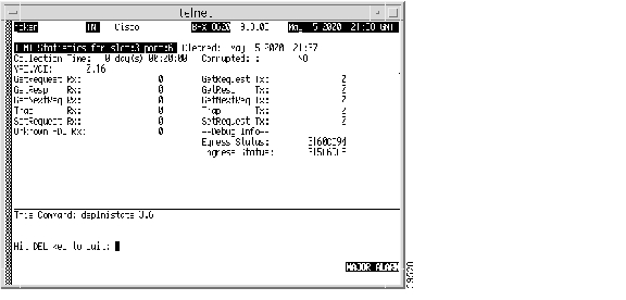
dspalms
sw150 TN Cisco IGX 8420 9.3.2R Dec. 14 2000 09:23 PSTAlarm summary (Configured alarm slots: None)Connections Failed: NoneTRK Alarms: NoneCircuit Line Alarms: NonePhysical Line Alarms: NoneCards Failed: 2Missing Cards: NoneRemote Node Alarms: 1 Unreachable, 2 Majors, 5 MinorsInterface Shelf Alarms: NoneFastPAD/Access Dev Alms: NoneLast Command: dspalmsNext Command:MAJOR ALARMExample
Display the current alarms on an IGX node with a Universal Routing Module (URM). Check the operational status of the embedded IOS-based router. When the router is not operational, the IOS field shows the router as unavailable and reports the URM slot number. A "Minor Alarm" is also displayed when the router is not operational.
dspalms
sw190 TRM Cisco IGX 8420 9.3.e8 Oct. 4 2000 10:38 GMTAlarm summary (Configured alarm slots:None)Connections Failed: NoneTRK Alarms: NoneCircuit Line Alarms: NonePhysical Line Alarms: NoneCards Failed: NoneMissing Cards: NoneRemote Node Alarms: NoneIOS Unavailable in 1 slotInterface Shelf Alarms: NoneFastPAD/Access Dev Alms: NoneLast Command:dspalmsNext Command:Minor Alarmdspapsln (display APS lines)
The dspapsln command displays the currently configured APS lines and their status.
Syntax
dspapsln
Attributes
Related Commands
addapsln, delapsln, cnfapsln, cnfapsln, dspapsln, dsplog, dspalms
Example
Display all the currently configured APS lines and their status.
dspapsln
alexa TRM genre BPX 8600 9.3 Apr. 13 2000 16:25 PDTActv Active Line Standby Line Current APS Last UserWork/Protect Line Alarm Status Alarm Status Alarm Status Switch Req2.1 3.1 PROT OK OK Loss of Sig(RED) Clear5.1 5.2 WORK OK LOS LOS Lockout6.3 6.4 NONE Deactivated APS Deactivated10.1 11.1 PROT OK OK Standard Mismatch ClearCommand: dspapslnExample
Display currently configured APS lines and their status.
dspapsln
sw117 TRM genre BPX 8620 9.3 Apr. 13 2000 16:25 PDTWork/Protect Actv Active Line Standby Line Current APS Last User(Work 1/Work 2) Line Alarm Status Alarm Status Alarm Status Switch Req2.2 3.2 WORK Loss of Sig (RED) Remote (YEL) Remote (YEL) ClearCommand: dspapslndspasich (display ASI channel routing entry)
Displays the ATM channel routing entries for an ASI card.
Syntax
dspasich <line> <channel>
Parameters
<line>
Specifies the line in the format slot.port.
<channel>
Specifies the channel in the format vpi.vci.
Attributes
Example: ASI Channel Routing Entry
dspasich 5.1 1 N
pubsbpx1 VT SuperUser BPX 15 9.3 Apr. 13 2000 21:09 GMTASI Channel Configuration Query & DisplaySlot.port.lcn:5.1.1Status: Added BF hdr: 4145 9002 8012 0501 8640 0000 2DEB[00] BF tp: 4 [11] VCI: 00000064 [22] UPC CDV: 0 [33] FST up: 0[01] Pri SDA: 5 [12] Con tp: VC [23] UPC CIR: 500 [34] FST dn: 0[02] Dst Prt: 1 [13] Rmt tp: ASI [24] UPC CBS: 1000 [35] FST fdn: 0[03] Dst lcn: 2 [14] Srv tp: VBR [25] UPC IBS: 0 [36] FST rmx: 0[04] BCF tp: 0 [15] Gen AIS: N [26] UPC MFS: 200 [37] Q max:64000[05] Qbin#: 12 [16] Mcst: 0 [27] CLP enb: Y [38] EFCI: 100[06] BF VPI: 64 [17] Mc grp: 1 [28] FST enb: N [39] CLP hi: 100[07] BF VCI: 0 [18] & msk: 0000000F [29] FST MIR: 500 [40] CLP lo: 100[08] Pl Cls: 0 [19] | msk: 06400640 [30] FST PIR: 500 [41] BCM: N[09] Rmt lp: N [20] Prt QBN: 2 [31] FST QIR: 500 [42] Inhibit:N[10] VPI: 00000064 [21] UPC GCR: 0 [32] QIR TO: 0 [43] UPC enb:YLast Command: dspasich 5.1 1 NNext Command:dspasm (display ASM card)
Displays BPX node alarms that, when active, produce an external alarm output (relay closure). These alarms are associated with powering and cooling the node as well as a statistics count.
For example, a minor alarm is generated when a fan speed drops below 2000 rpm. Because the single ASM card is always located in slot 15, you do not need to enter a card slot for this command. To configure the ASM alarms, use cnfasm (a SuperUser command).
Syntax
dspasm
Attributes
Related Commands
cnfasm
Example
Display the ASM card parameters.
dspasm
D1.jea TRM SuperUser BPX 8620 9.3 Apr. 13 2000 12:24 GMTASM Status: Active ASM AlarmsStatistics count: 7 Fan #1 RPM out of rangeStatistics timeouts: 0 Fan #2 RPM out of rangeCabinet temperature: 21 C Fan #3 RPM out of rangePower voltage A/B: 0.0 / 0.0 VPSU Ins Type Rev SerNum FailureA N N/A N/A N/A N/AB N N/A N/A N/A N/AFAN 1 2 30000 0000 0000 RPMLast Command: dspasmNext Command:dspatmcls (display ATM connection class)
Displays the current parameters for an ATM connection class template. There are ten number classes. The parameters and the values for each varies with the connection type (CBR, VBR, ABR, and ATFR).
Syntax
dspatmcls <class number>
Parameters
class number
Specifies the class whose current parameters you want to see.
Range: 1-10
Attributes
Related Commands
addcon, cnfatmcls, dspcls, cnfcls, dspcon, dspcons
Example
Display the parameters for configuration class 1.
dspatmcls 1
night TN SuperUser BPX 8620 9.3 Apr. 13 2000 13:22 GMTATM Connection ClassesClass: 1Type: VBRUPC SCR IBS MBS ABR PCR ABR PCRy 500/500 10/10 1000/1000 - 500/500 -/-ICR ICR TO Rate Up Rate Dn Rate FastDn Max Adjust CDVT[in cells]-/- - - - - - 64000/64000EFCI % Util FGCRA MFS CLP CLP Hi CLP Lo BCM100/100 100/100 n/n -/- y 100/100 100/100 n/nDescription: "Default VBR 500"Last Command: dspatmcls 1Next Command:Example
Display the parameters for configuration class 1.
dspatmcls 1
night TN SuperUser BPX 8620 9.3 Apr. 13 2000 13:22 GMTATM Connection ClassesClass: 3 Type: rt-VBRPCR(0+1) %Util CDVT(0+1) AAL5 FBTC SCR2000/2000 100/100 10000/10000 n 2000/2000MBS Policing1000/1000 3Description: "Default rt-VBR 2000"_____________________________________________Class: 4 Type: rt-VBRPCR(0+1) %Util CDVT(0+1) AAL5 FBTC SCR8000/8000 100/100 10000/10000 n 8000/8000MBS Policing1000/1000 3Description: "Default nrt-VBR 8000"Last Command: dspatmcls 1Next Command:dspbmpparm (display priority bumping parameters)
Displays the priority bumping parameters.
Syntax
dspbmpparm
Parameters
Attributes
Related Commands
cnfbmpparm
Example
Use dspbmpparm to view the priority bumping parameters. Priority bumping for the whole network is shown at the top of the display, and then at the bottom for a specific node.
igxr2 TN StrataCom IGX 8420 9.3.0K Jan. 26 2000 15:19 PDT1 Priority Bumping Enabled [ YES]2 Priority Bumping Bundle [ 10] (D)3 Priority Bumping Bands:Bumping Band 1 [ 2] (D)Bumping Band 2 [ 4] (D)Bumping Band 3 [ 6] (D)Bumping Band 4 [ 8] (D)Bumping Band 5 [ 10] (D)Bumping Band 6 [ 12] (D)Bumping Band 7 [ 14] (D)Priority Bumping Active on this node [ YES]Number of Priority Bumping Bands [ 7] (D)Last Command: dspbmpparmbpx1 TN StrataCom BPX 8620 9.3.0K Jan. 26 2000 14:20 PST1 Priority Bumping Enabled [ YES]2 Priority Bumping Bundle [ 10] (D)3 Priority Bumping Bands:Bumping Band 1 [ 2] (D)Bumping Band 2 [ 4] (D)Bumping Band 3 [ 6] (D)Bumping Band 4 [ 8] (D)Bumping Band 5 [ 10] (D)Bumping Band 6 [ 12] (D)Bumping Band 7 [ 14] (D)Priority Bumping Active on this node [ NO]Number of Priority Bumping Bands [ 0] (D)Last Command: dspbmpparmdspbmpstats (display priority bumping statistics)
Displays priority bumping operational statistics for the priority bumping feature.
Syntax
dspbmpstats
Attributes
Related Commands
dspbmpparm, cnfbmpparm, dsprrst s, rrtinf
Display Fields
Example (BPX)
dspbmpstats
sw67 TN StrataCom BPX 8620 9.3.0L Jan. 28 2000 18:57 PSTPB Routing StatisticLatest bumping band - Latest bumped band -Hwm bumping band - Lwm bumped band -Latest # bumping conns/req 0 Latest # bumped conns/req 0Hwm # bumping conns/req 0 Hwm # bumped conns/req 0Accum # bumping conns 0 Accum # bumped Lcons 0Avg # bumping conns/req 0.00 Accum # bumped VLcons 0Last Command: dspbmpstatsdspbob (display breakout box)
Shows the current state of all inputs from user equipment to the node the state of all outputs from the node to the user equipment. The display is real-time and updated at a user-specified interval. The display refreshes at the designated interval until the Delete key is pressed or until it times out.
See the cnfict description for information on configuring data interfaces. When used with Frame Relay T1/E1 applications, dspbob displays the message "This FRP does not support V.35 ports."
Displaying Signal Status for Port Concentrator Ports
If an FRM-2 or FRP-2 card connects to a Port Concentrator Shelf (PCS), you can specify up to 44 ports by using the port parameter. In this case, dspbob displays the signal status for ports on the PCS. The PCS relays any changes in signal states to the FRM-2 or FRP-2, so a slight delay occurs when signals are updated.
When used for PCS ports, dspbob has an optional parameter measuring port clock speed. Selection of this parameter temporarily interrupts all traffic on the logical port. The events that take place upon input of this parameter are:
1.
2.
3.
Syntax
dspbob <slot><port> [interval] [(measure clock speed) y | n ]
Parameters
Attributes
Related Commands
cnfict, dspcon, dspict
Example
See the breakout box display for channel 5.1.
dspbob 5.1
alpha TRM YourID:1 IGX 8420 9.3 Apr. 13 2000 11:29 PSTPort: 5.1Interface: V35 DCEClocking: Normal (255999 Baud)Inputs from User Equipment Outputs to User EquipmentLead Pin State Lead Pin State Lead Pin State Lead Pin StateRTS C Off CTS D OnDTR H Off DSR E OnTxD P/S Idle DCD F OffTT U/W Unused RI J OffTM K OffRxD R/T IdleRxC V/X ActiveTxC Y/a ActiveThis Command: dspbob 5.1Hit DEL key to quit:Example
See the breakout box display for Frame Relay connections.
dspbob 9.1
alpha TRM YourID:1 IGX 8420 9.3 Apr. 13 2000 11:29 PSTPort: 9.1Interface: FRI-V35 DTEClocking: NormalInputs from User Equipment Outputs to User EquipmentLead Pin State Lead Pin State Lead Pin State Lead Pin StateCTS D Off RTS C OnDSR E Off DTR H OnDCD F Off LT L Off(TM) n Off (RLB) N OffThis Command: dspbob 9.1Hit DEL key to quit:dspbpnv (display backplane NOVRAM)
Issue the dspbpnv command to see the NOVRAM setting for the backplane. For some operations, you must verify if the node has the new backplane or the old backplane. For example, in order for the BPX 8600 to operate at 19.2 Gbps with the BCC-4V, it must have the NOVRAM Word #2 set to 0001 (which indicates that the backplane version is new). If it instead has the NOVRAM Word# set to 0000 (indicating that the backplane version is old) the switch cannot run with a 19.2 Gbps peak throughput. If you visually verify that the backplane is a 19.2 Gbps backplane (see note below), but the backplane NOVRAM Word #2 has not been set to 0001, then issue the cnfbpnv command to program the NOVRAM.
Note
The following table details the bit fields for the BCC Backplane NOVRAM format. The display in the field Word 2 describes the backplane type.
Syntax
dspbpnv
Attributes
Related Commands
cnfbpnv
Example (BPX)
View the NOVRAM settings on a BPX 8620.
dspbpnv
sw217 TN Cisco BPX 8620 9.3.x5 June 11 2001 14:34 GMTBackPlane NOVRAM----------------WORD 0: 0x0096 WORD 1: 0x0065WORD 2: 0x0000 WORD 3: 0x3232WORD 4: 0x3037 WORD 5: 0x3632WORD 6: 0x0000 WORD 7: 0x0000WORD 8: 0x0000 WORD 9: 0x0000WORD 10: 0x0000 WORD 11: 0x0000WORD 12: 0x0000 WORD 13: 0x0000WORD 14: 0x0000 WORD 15: 0x9997Last Command: dspbpnv
dspbusbw (display cell bus bandwidth for UXM cards)
Displays the amount of bandwidth allocated on the cell bus on an IGX node. By default, the system allocates enough bus bandwidth for one OC-3 when the first line is upped by using the upln command. If there is not enough allocated cell bus bandwidth, the line is not upped. Cell bus bandwidth must be allocated before adding connections on the UXM card.
Syntax
dspbusbw <slot> [u]
Parameters
Display Fields
Attributes
Related Commands
cnfbusbw
Example
Display the amount of bandwidth allocated on the cell bus on the UXM card in slot 6 of the IGX node.
dspbusbw 6
Get updated bandwidth info from card (Y/N)? nsw199 TN StrataCom IGX 16 9.3 Apr. 13 2000 17:52 GMT1\NBus Bandwidth Usage for UXM card in slot 6 Last Updated on 04/07/98 12:03:00FPkts/sec Cells/sec UBUsMinimum Reqd Bandwidth: 0 0 0Average Used Bandwidth: 0 0 0Peak Used Bandwidth: 0 0 0Maximum Port Bandwidth: - 10866 3Allocated Bandwidth: 8(Cell Only): - 32000(Cell+Fpkt): 16000 24000(Fpkts / 2 + Cells) <= 32000Reserved Bandwidth: - 4000 1Last Command: dspbusbw 6Next Command: dspbusbw 6Get updated bandwidth info from card (Y/N)? ysw199 TN StrataCom IGX 16 9.3 Apr. 13 2000 17:53 GMT1\NBus Bandwidth Usage for UXM card in slot 6 Last Updated on 04/09/98 17:53:22FPkts/sec Cells/sec UBUsMinimum Reqd Bandwidth: 0 0 0Average Used Bandwidth: 0 0 0Peak Used Bandwidth: 0 0 0Maximum Port Bandwidth: - 10866 3Allocated Bandwidth: 8(Cell Only): - 32000(Cell+Fpkt): 16000 24000(Fpkts / 2 + Cells) <= 32000Reserved Bandwidth: - 4000 1Last Command: dspbusbw 6dspbuses (display bus status)
Displays the available Muxbus or cell bus bandwidth. The display does not dynamically receive updates and is therefore a snapshot. The dspbuses command lists the dedicated and pooled bandwidth units as well as the status of the available Muxbus.
As a safeguard against bus failure, each node is equipped with redundant System Buses: Bus A and Bus B. Either bus can be configured as the active bus with the other bus as standby. Use the cnfbus command to switch the active bus.
Each System Bus contains these buses:
•
•
•
•
In addition to showing which System Bus is active and which is standby, the dspbuses command also shows which sub-bus needs diagnostics or has failed. Bus status is displayed at the bottom of the screen. Table 4-3 shows the possible status displays and their meaning.
The remaining cell bus bandwidth available to assign to cards and circuits is displayed. This is primarily used when configuring the AIT card on the IGX node. You can assign CELLBUS bandwidth for the IGX node.
Available bandwidth falls into two categories:
•
Dedicated bandwidth is reserved by the system for specific purposes, such as Statistical Reserve for PCC traffic.•
Pooled bandwidth can be assigned to any use but primarily is used for an ATM trunk.Cell bus bandwidth is assigned in quantities of "switches," "slices," and "circuits" and the available bandwidth is displayed in three rows accordingly. A single DS0 circuit occupies 333 packets per second (pps) of cell bus bandwidth, a "slice" of bandwidth is equivalent to three DS0 circuits for a total of 1000 pps. A switch is eight slices for a total of 8000 packets/second of bus bandwidth.
In a newly installed node with no cards and no circuits installed, the total bus bandwidth that is available to be assigned is listed in the right column of the following table, which is the sum of the dedicated and pooled bandwidth. As cards and circuits are added to the node, the available bandwidth decreases accordingly.
Table 4-4 Bandwidth Units and Capacity
switch
8 slices or 8000 pps
20
slice
3 DS0s or 1000 pps
160
DS0
333 pps
480
Syntax
dspbuses
Attributes
Related Commands
cnfbus
Example (BPX)
dspbuses
bpx1 TN SuperUser BPX 15 9.3 Apr. 13 2000 13:22 GMTBus StatusBus A (slot 7): Active - OKBus B (slot 8): Standby - OKLast Command: dspbusesNext Command:Example (IGX)
dspbuses
sw197 TN SuperUser IGX 8420 9.3 Apr. 13 2000 04:10 GMTBus InfoBus Bandwidth usage in Fastpackets/second (Snapshot)Allocated = 86000 ( 8%)Available = 1082000 (92%)-----------Bus A: Active - OKBus B: Standby - OKLast Command: dspbusesExample (IGX)
Display status and bandwidth available. The status of Bus A and Bus B is displayed. In this example, both buses are OK and B is the active control bus (normal operation is for bus A to be the active bus).
dspbuses
alpha TRM YourID:1 IGX 8420 9.3 Apr. 13 2000 13:34 PSTBus InfoAvailable MUXBUS bandwidth (snapshot)Dedicated Pooled Units--------- ------ -----0 13 8000 pkts/sec5 104 1000 pkts/sec22 312 ds0 circuitsBus Status-----------Bus A: Standby - OKBus B: Active - OKLast Command: dspbusesNext Command:dspcdstats (display UXM card statistics)
The dspcdstats command displays the collected UXM card statistics for the selected node slot.
Syntax
dspcdstats <slot number>
Parameters
Attributes
Related Commands
cnfslotstats, dspsloterrs (for BXM)
Example (IGX)
Display UXM Card Statistics
dspcdstats 9
bolger TN Cisco IGX 8430 9.3.3q May 25 2001 12:23 PSTSlot 9Collection Time: 1 day(s) 03:15:51 Clrd: Date/Time Not SetType CountQBIN: Ingress Cells Rcv from ln 22QBIN: Ingress Cells Tx to net 22QBIN: Ingress Cells discarded 0QBIN: Ingress FPs Rcv from ln 68013QBIN: Ingress FPs Tx to net 68013QBIN: Ingress FPs discarded 0This Command: dspcdstats 9Example (IGX) Field Descriptions
dspcbause (display CBA block usage)
Queries the specified slot and displays information about the CBA blocks. While running this command, it periodically queries the card and the display continuously updates the CBA parameters, showing block usage among AutoRoute and VSI.
To display a summary of CBA usage on all active UXMs on the node, enter dspcbause with no parameters.
To display CBA usage on a specific active UXM card, enter dspcbause with the slot number parameter.
Syntax
dspcbause [slot_no] [interval]
Parameters
[slot_no]
Optionally specifies the slot number of a particular UXM card.
[interval]
Optionally specifies the interval in seconds. Default: 10 seconds.
Display Fields
Attributes
Example
dspcbause
Display CBA and CBA block use of Automatic Routing Management and VSI (on a node).
sw188 TRM Cisco IGX 8420 9.3.1c Aug. 17 2000 11:10 PSTVSI CBA allocation summary for all slots :Slot VSI LCNs CBA Blks Actual CBA Blksto be alloced alloced4 200 7 75 2000 63 63Last Command: dspcbauseNext Command:Example
Display CBA and CBA block use among AutoRoute and VSI (on a slot).
dspcbause 5
sw188 TRM Cisco IGX 8420 9.3.1c Aug. 17 2000 11:11 PSTCBA Usage for slot 5CBA Blocks allocated = 63 CBA Blocks used = 16CBA Block Bitmap:80 : 0 0 0 0 0 0 0 0 0 0 0 0 0 0 0 0 0 0 0 0 0 0 0 0140 : 0 0 0 0 0 0 0 0 0 0 0 0 0 0 0 0 0 0 0 0 0 0 0 0200 : 0 0 0 0 0 0 0 0 0 0 0 0 0 0 0 0 0 0 0 0 0 0 0 02C0 : 0 0 0 0 0 0 0 0 0 0 0 0 0 0 0 0 0 0 0 0 0 0 0 0380 : 0 0 0 0 0 0 0 0 0 0 0 0 0 0 0 0 0 0 0 0 0 0 0 0440 : 0 0 0 0 0 0 0 0 0 0 0 0 0 0 0 0 0 0 0 0 0 0 0 0500 : 0 0 0 0 0 0 0 0 0 0 0 0 0 0 0 0 0 0 0 0 0 0 0 05C0 : 0 0 0 0 0 0 0 0 0 0 0 0 0 0 0 0 0 0 0 0 0 0 0 0680 : 0 0 F8 FF 7 0 0 0 0 0 0 0This Command: dspcbause 5Hit DEL key to quit:dspcd (display card)
Displays the status, revision, serial number, and top assembly number of a card. If a back card is present, its type, revision, and serial number appear. The displayed information can vary with different card types and appears on a single-page display.
Syntax
dspcd <slot number>
Parameters
<slot number>
Specifies the slot number of the card for which you wish to see status and identifying information.
Attributes
Related Commands
dncd, dspcds, resetcd, upcd
Example (BPX) BXM-155
Display features supported (Support fields) on the BXM card in slot 2. The front card supports the Neighbor Discovery feature (NbrDisc) and the XLMI protocol (XL). Both the LMI Neighbor Discovery feature and XLMI protocol are required for AR-PNNI links in a hybrid network.
dspcd 1
BPX02 TN Cisco BPX 8620 9.3.3W Aug. 13 2001 11:24 PDTDetailed Card Display for BXM-155 in slot 1Status: ActiveRevision: FA21 Backcard InstalledSerial Number: A66165 Type: LM-BXMTop Asm Number: 80033333 Revision: BBQueue Size: 524280 Serial Number: 770491Supp:8 Pts, OC3, FST, VcShp Top Asm Number:Supp: VT,ChStLv 1,VSI(Lv 3,ITSM) Supp: 8 Pts,OC3,MMF,RedSlot:NOSupp: APS(FW), F4F5Support: LMIv 1,ILMIv 1,NbrDisc,XLSupp: OAMLp,TrfcGen,PPDPolic,OAM-E#Ch:32768,PG[1]:32736,PG[2]:32736PG[1]:1,2,3,4,PG[2]:5,6,7,8,#Sched_Ch:61440 #Total_Ch:61376Type: BXME, revision DXLast Command: dspcd 1
Table 4-6 Display Fields for Example (BPX) BXM-155
BXM Front Card Fields
Status
Displays the status of a card.
Active
Card in use, no failure detected.
Active—F
Card in use, failure detected.
Active—T
Card active, test in progress.
Active—F-T
Card active, minor failure detected, test in progress.
Standby
Card idle, no failure.
Standby—F
Card idle, failure detected.
Standby—T
Card idle, test in progress.
Standby—F-T
Card idle, failure detected, test in progress.
Failed
Card failed.
Down
Card downed by user.
Down—F
Card downed, failure detected.
Down—T
Card downed, failure detected, test in progress.
Mismatch
Mismatch between front card and back card.
Update *
Configuration RAM being updated from active control card.
Locked*
Old software version is being maintained in case it is needed.
Dnlding*
Downloading new system software from the active PCC adjacent node from WAN Manager.
Dnldr*
Looking to adjacent nodes or WAN Manager for either software to load or other software needs you have not specifically requested.
Program
Occurs when new firmware is being burned on the card.
Revision
The firmware/hardware version ID.
Serial Number
The serial number of the card.
Top Asm Number
The card's 800-level part number.
Queue Size
The sum of the sizes of the ATM cell queues in one direction. Queue size = size of HP+TS+BDATA+BDATB+CBR+VBR +SIG+ABR queues.
Support or Supp
The features that the card's firmware and hardware supports.
Pts
The number of physical ports supported by card hardware: OC3 | OC12 |T3 | E3
The card type supported
Indicates firmware supports Foresight.
VcShp
Indicates firmware supports VCshaping.
VT
Indicates firmware supports virtual trunks
ChStLv
The multilevel channel statistics level currently programmed 0-3. The statistics level is configured using the command cnfcdparm. Refer to cnfcdparm (configure card parameters), page 3-143 for more information about multilevel channel statistics.
VSI
The VSI attributes supported. Values are:
lv-VSI level supported by firmware. The level is 0, 1, 2, or 3; the level represents the resources supported, i.e. LCNs, VPI, etc.
ITSM-VSI level supported by firmware.
I = ILMI support.
T = topology support.
S = signalling, QBIN support.
M = multiple partition support.
V = VC merge support.
APS
The APS attributes supported. Values are:
APS(FW)-APS is supported by card firmware.
APS(HW1+1)-APS 1+1 is supported by card hardware.
APS(ChHlv)-The number of channels supported by card is halved in order to support APS 1:1.
F4F5
F4 AIS detection on trunks and F4 AIS to F5 AIS mapping on ports is supported by card firmware.
LMIv
LMI version supported by card firmware.
ILMIv
ILMI version supported by card firmware.
NbrDisc
ILMI neighbor discovery is supported by card firmware.
OAMLp
OAM loopback testing is supported by card firmware.
XL
XLMI protocol supported by card firmware.
TrfcGen
Traffic Generation testing is supported by card firmware.
PPDPolic
OAM-E
OAM Ping feature supported by card firmware.
#Ch
The total number of channels supported by all port groups.
PG[1]:8160 PG[2]:8160
The number of channels contained in each port group.
PG[1]:1,2,3,4,
PG[2]:5,6,7,8
The card physical ports.
#Sched_Ch
The number of scheduler channels supported by card.
#Total_Ch
The total number of channels reported by the BXM cards.
BXM Back Card Fields
Type
The type of backcard: LM-BXM, T3-3, E3-3, T3-2, E3-2, SMF, MMF, SMFLR, LMASM, STM1, UTP, STP.
Revision
The hardware version ID.
Serial Number
The serial number of the card.
Top Asm Number
(TAN) The 800-level part number of the card.
Supp
The resources and features this card supports. For example:
8 Pts,OC3,SMF,APS,RedSlot:2
Pts
The number of ports on the backcard
OC3
Supports SONET OC3 with SMF
Supp (cont.)
APS
Supports APS 1:1
RedSlot:<slot number>
If APS 1+1 supported by the backcard, and configured, this field shows the redundant card's slot number. Values are:
??- If APS 1+1 supported by the backcard, but not configured.
NO- If APS 1+1 is not supported by the backcard.
Example (IGX) UXM
Detailed Card Display for UXM card in slot 9.
dspcd 9
sbolger TN Cisco IGX 8430 9.3.3o May 17 2001 17:43 PSTDetailed Card Display for UXM in slot 9Status: Active Front Card Supports:Revision: CD02 Vtrunks, OAMLpbk & TrfcGen, ILMI ver 1,Serial Number: 284344 Neighbor Discovery, SIW, CGW, CellFwd,Top Asm Number: 28216402 Hot Standby, Trfc Shaping, IMA,Backplane Installed ChnStatLvl 1, NumChans = 8000,Backcard Installed NumRCMP = 8191, VSI ver 2, VSI CtrlrType: OC3Revision: ADSerial Number: 258051Top Asm Number: 28226303Ports: 4Line Mode: SMFLast Command: dspcd 9Next Command:
Example (BPX)
Displays Neighbor Discovery support under the Front Card Supports field for a BXM card in slot 13, and VC Merge support, designated by V in:
Supp: VT,ChStLv 1,VSI(Lv 3,ITSMV)
dspcd 13
ssw177 TN Cisco BPX 8620 9.3.c3 May 4 200123:39 GMTDetailed Card Display for BXM-155 in slot 13Status: ActiveRevision: FAL Backcard InstalledSerial Number: A66604 Type: LM-BXMTop Asm Number: 8000309303 Revision: BBQueue Size: 260090 Serial Number: A84438Support: 4 Pts, OC3, FST, VcShp Top Asm Number:Supp: VT,ChStLv 1,VSI(Lv 3,ITSMV) Supp:8 Pts,OC3,MMF,RedSlot:NOSupp: APS(FW)Support: LMIv 1,ILMIv 1,NbrDisc,XLSupport: OAMLp, TrfcGen, PPDPolic#Ch:32768,PG[1]:32736,PG[2]:32736PG[1]:1,2,PG[2]:3,4,#Sched_Ch:61440 #Total_Ch:61376Type: BXME, revision DXdspcderrs (display card errors)
Displays detailed card failure information resulting from card diagnostics testing at the local node.
This command displays a history of card failures associated with a specified slot. If no argument is specified, a summary is displayed, indicating which slots have failures recorded against them. The command displays the results of the self-tests and background tests as well as the total hardware errors.
To clear the card error counters, use the clrcderrs command. To obtain a hard copy of the report, use the prtcderrs command.
Syntax
dspcderrs [<slot>]
Parameters
Attributes
Related Commands
clrcderrs, prtcderrs
Example
Display card errors on the card in slot 11.
dspcderrs 11
sw83 TN SuperUser IGX 8420 9.3 Apr. 13 2000 17:56 PSTAIT in Slot 11 : 176767 Rev AEF Failures Cleared: Apr. 13 2000 11:25:29 PST----------------------------------- Records Cleared: Apr. 13 2000 13:14:03 PSTSelf Test Threshold Counter: 0 Threshold Limit: 300Total Pass: 0 Total Fail: 0 Total Abort: 0First Pass: Last Pass:First Fail: Last Fail:Hardware Error Total Events: 0 Threshold Counter: 0First Event: Last Event:Last Command: dspcderrs 11Next Command:dspcdred (display redundant cards)
The command dspcdred has the same functionality as the command dspyred; therefore, please use the command dspyred. For information about dspyred command usage, refer to dspyred (display Y-cable redundancy).
dspcds (display cards)
Displays the cards in a shelf, front and back, with their type, revision, and status. For front and back card sets, the status field applies to the cards as a set. A "T" opposite a card indicates that it is running a self-test or a background test. An "F" opposite a card indicates that it has failed a test.
If lines or connections have been configured for a slot, but no suitable card is present, the display lists the missing cards at the top of the screen.
If a special backplane is installed or if a card was previously installed, empty slots are identified as "reserved."
For a two-shelf node, the screen initially displays only the upper shelf with a "Continue?" prompt. Typing "y" to the prompt displays the cards in the lower shelf. For an IGX 8410 node, the card information appears in only the left column.
Syntax
dspcds [l]
Parameters
l
Directs the system to display status of the cards on just the lower shelf of an IGX 32 node.
Attributes
Related Commands
dncd, dspcd, resetcd, upcd
Display Cards Update and Status Display Fields
In the preceding messages, an asterisk (*) means an additional status designation for BCC or NPM cards. An "F" flag in the card status indicates that a non-terminal failure was detected. Cards with an "F" status are activated only when necessary (for example, when no other card of that type is available). Cards with a "Failed" status are never activated.
The "reserved for" logic in Release 9.2 reserves the slot for a BXM if SONET APS (Automatic Protection Switching) has been configured on the slot.
To support the Hitless Rebuild feature in Release 9.2, after a switchover has occurred and the standby updates are about to begin, the dspcds command shows the standby processor card as missing temporarily. This is a result of the delay in performing the full rebuild on the standby processor, which is necessary as part of the hitless rebuild sequence.
Following any processor card switchover, the new standby rebuilds, preserving the critical databases needed for a hitless rebuild. When database updates can start, the standby rebuilds again doing a normal standby rebuild. If there is a failure on the new active card that causes it to switch back before updates can start, the card taking over performs a hitless rebuild. Under most conditions, the second switchover is not necessary, and a full rebuild is done on the standby processor. As this process begins, the standby card briefly appears to be missing.
Example (URM on IGX)
Display the status of cards in an IGX node with Universal Router Module (URM) cards.
dspcds
sw175 TN Cisco IGX 8420 9.3.q6 Mar. 9 2000 05:21 GMTMissing Cards: 1 NPMFrontCard BackCard FrontCard BackCardType Rev Type Rev Status Type Rev Type Rev Status1 NPM FMR Active 9 FRM ESX FRI-T1 AL Standby2 Empty reserved for NPM 10 URM BA03 2FE P03 Standby3 Empty 11 URM BA04 2FE P03 Standby-T4 Empty 12 NTM EKJ Empty Standby5 UXM CAA Empty Standby 13 Empty6 URM BA04 Empty Standby 14 Empty7 UXM BDJ E1-IMA AC Standby-T 15 Empty8 Empty 16 URM BA03 2FE P03 StandbyLast Command:dspcdsExample (OC-12 on BPX)
Display status of cards on a BPX node. The two-port BME card with OC-12 interface is in slot 11.
dspcds
sw60 TN SuperUser BPX 15 9.3 Apr. 13 2000 11:36 GMTMissing Cards: 1 BCCFrontCard BackCard FrontCard BackCardType Rev Type Rev Status Type Rev Type Rev Status1 BNI-T3 CCF T3-3 BE Active 9 BNI-155 BDK MMF-2 CM Standby2 Empty 10 Empty3 ASI-T3 BJF T3-2 AA Standby 11 BME-622 K08 11LM-BXM P02AB Active4 ASI-E3 BMJ E3-2 BE Standby 12 ASI-155 BDK MMF-2 AB Standby5 BNI-E3 CMF E3-3 EY Standby 13 Empty6 Empty 14 Empty7 BCC BWF LMBCC AC Active 15 ASM ACA LMASM AC Active8 Empty reserved for CardLast Command: dspcdsdspcftst (display communication fail test pattern)
Displays the test pattern used for the communications fail test.
This test pattern is used to test the controller communication path to a node that does not respond to normal controller traffic. The test pattern defaults to an alternating 8-byte sequence of 00 and FF. Refer to cnfcftst command for other patterns and how to reconfigure this pattern.
Syntax
dspcftst
Attributes
Related Commands
cnfcftst
Example
dspcftst
sw83 TN SuperUser IGX 8420 9.3 Apr. 13 2000 17:57 PSTComm Fail Test Pattern.Byte 0: FF Byte 12: 00 Byte 24: FF Byte 36: 00 Byte 48: FFByte 1: FF Byte 13: 00 Byte 25: FF Byte 37: 00 Byte 49: FFByte 2: FF Byte 14: 00 Byte 26: FF Byte 38: 00 Byte 50: FFByte 3: FF Byte 15: 00 Byte 27: FF Byte 39: 00 Byte 51: FFByte 4: 00 Byte 16: FF Byte 28: 00 Byte 40: FF Byte 52: 00Byte 5: 00 Byte 17: FF Byte 29: 00 Byte 41: FF Byte 53: 00Byte 6: 00 Byte 18: FF Byte 30: 00 Byte 42: FF Byte 54: 00Byte 7: 00 Byte 19: FF Byte 31: 00 Byte 43: FF Byte 55: 00Byte 8: FF Byte 20: 00 Byte 32: FF Byte 44: 00 Byte 56: FFByte 9: FF Byte 21: 00 Byte 33: FF Byte 45: 00 Byte 57: FFByte 10: FF Byte 22: 00 Byte 34: FF Byte 46: 00 Byte 58: FFByte 11: FF Byte 23: 00 Byte 35: FF Byte 47: 00 Byte 59: FFLast Command: dspcftstNext Command:dspchan (display channel configuration)
Displays the configuration of IGX voice channels. This is primarily a debug command that allows you to inspect the data structure defining a channel. Parameters for voice and signaling processing on a CVM voice channel are displayed by this command. Table 4-8 lists the displayed CVM parameters. Many of these parameters are also displayed elsewhere.
Syntax
dspchan <channel>
Parameters
Attributes
Related Commands
cnfcdpparm
CVM Voice Channel Parameters
Example (IGX)
dspchan 7.1
sw83 TN SuperUser IGX 8420 9.3 Apr. 13 2000 18:06 PSTChannel Data Base for CDP card 7 chan. 000000 at address 30BF29ECVC Index -1 Onhk C 4In Loss 0 Onhk D 4Out Loss 0 Dial Type 0Chan Type 1 TX A bit 1Sig. Intg 96 TX B bit 1Xmt. dlay 5 TX C bit 0Smpl dlay 1 TX D bit 1Bk noise 67 RX A bit 1DSI smple 168 RX B bit 1Chan Util 40 RX C bit 0Onhk A 3 RX D bit 1Onhk B 3 Signaling TSP MODEThis Command: dspchan 7.1Continue?sw83 TN SuperUser IGX 8420 9.3 Apr. 13 2000 18:07 PSTChannel Data Base for CDP card 7 chan. 000000 at address 30BF29ECTX CODE 3 iec cancel 0RX CODE 3 iec nlp 1TX SIG 0 iec converg. 1RX SIG 0 iec erl lvl 1CLR CHN 0 iec Hregs. 1SIG RATE 0 iec tone dsbl 1PLY MSBhx 1 adpcm flag 0PLY LSBhx 90In use 0DPU -Last Command: dspchan 7.1Next Command:Example (BPX)
dspchan 11.1
sw53 TN Cisco BPX 8620 9.3.m0 Dec. 12 2000 12:16 GMTChannel Data Base for 11.1 on BXM at address 0x325C48DApcnfg_nm_chans 0 apc_metro 0pcnfg_bandwidth 353208 pcnfg_basis 0pcnfg_frst_indx 0 apc_t1_basis 0pcnfg_chan_cnt 5 apc_nni_port 0pcnfg_loop 0pcnfg_state 1pcnfg_cnfg 1pcnfg_hipri 0pcnfg_com_fail 0pcnfg_ptp_conn 0Last Command: dspchan 11.1dspchcnf (display channel configuration)
Displays configuration details for voice, data, ATM, or Frame Relay channels.
Voice Channels
When you specify a voice channel with dspchcnf, the display shows configuration details for all channels on the specified circuit line starting with the specified channel:
•
•
•
•
•
•
•
Data Channels
The data cards that support this command are the HDM, LDM, UVM, and CVM/CVP cards on the IGX node.
For data connections on the specified card and starting with the specified channel, the dspchcnf command displays configuration details for all channels on the specified data card (CDP, SDP, or LDP) starting with the specified channel:
•
•
•
•
•
•
Frame Relay Channels
The display includes configuration details for all channels on the specified FRP port starting with the specified channel. If you specify a Frame Relay port only with no DLCI, the display includes configuration details for all channels on the Frame Relay port specified. The display also indicates either Cisco parameters or standard Frame Relay parameters where appropriate.
When you specify a Frame Relay channel with dspchcnf, the display shows:
•
•
•
•
•
•
•
•
Syntax
dspchcnf <start_channel>
Parameters
Attributes
Related Commands
cnfdch, cnfchadv, cnfchdfm, cnfchdl, cnfcheia, cnfchgn, cnfchtp, cnfchutl, cnffrcon, cnfchpri
Example (UVM on IGX)
Display the channel configuration of line 7.1.1-24. The card in slot 7 is a UVM.
dpchcnf 7.1.1
sw109 VT cisco IGX 8420 9.3 Apr. 13 2000 18:59 PST% Adaptive Gain (dB) Dial Interface OnHk CondChannels Util Voice Fax In Out Type Type A B C D Crit7.1.1-24 40 Enabled Disabled 0 0 Inband 2W E&M 0 X - - a7.2.1-24 40 Enabled Disabled 0 0 Inband Unconfig ? ? - - aLast Command: dspchcnf 7.1.1Next Command:Example (CVM on IGX)
Show channel configuration of line 13. The card in slot 13 is a CVM.
dspchcnf 13.1
sw150 TN Cisco IGX 8420 9.3.2T Dec. 19 2000 23:32 PST% Adaptive Gain (dB) Dial Interface OnHk CondChannels Util Voice Fax In Out Type Type A B C D Crit13.1-24 60 Enabled - 0 0 Inband Unconfig ? ? - - aLast Command: dspchcnf 13.1Example (Data Channels on IGX)
Show data channels starting at 13.1.
dspchcnf 13.1
sw180 TN Cisco IGX 8420 9.3.o1 Nov. 30 2000 12:15 GMTMaximum EIA % DFM Pattern DFM Idle Code PreAgeChannels Update Rate Util Length Status Suppr (usec)13.1-8 2 100 8 Enabled - 0Last Command: dspchcnf 13.1Example (Frame Relay on IGX)
Show data channels starting at 13.1.
dspchcnf 9.1
sw108 VT Cisco IGX 8420 9.3.q2 Dec. 20 2000 12:29 GMTFrame Relay Channel Configuration Port: 9.1From MIR CIR VCQ Dep PIR Cmax ECNQ Th QIR FST %Utl9.1.918 59.5 59.5 61440 59.5 10 21504 59.5 n 1009.1.919 19.2 19.2 61440 19.2 10 21504 19.2 n 1009.1.920 19.2 19.2 61440 19.2 10 21504 19.2 n 100Last Command: dspchcnf 9.1dspchdlcnf (display channel dial type configurations)
Displays dial type configurations for all channels on a circuit line:
Syntax
dspchdlcnf <start_channel>
Parameters
<start_channel>
Specifies the channel at which the display begins.
For a CDP or CVM, the format is slot.channel.
For a UVM, the format is slot.line.channel.
Attributes
Related Commands
cnfchdl
Display Fields
Example
Display the dial type configuration for all channels beginning with 14.1.
dspchdlcnf 14.1
alpha TRM YourID:1 IGX 8420 9.3 Apr. 13 2000 09:45 PSTChannels Type Sig Delay Min Wink IntDigit Time Playout Delay14.1-24 Inband 12 141 300 -Last Command: dspchdlcnf 14.1Next Command:dspchec (display channel echo canceller configuration)
Displays the integrated echo canceller (IEC) parameters for one or more voice channels. The dspchec command does not apply to CAS or data channels. The specified channels must be on a CDP, CVM, or UVM. See Table 4-4 for what dspchec displays.
Syntax
dspchec <channel>
Parameters
<channel>
Specifies the channel or channels to display.
For a CVM or CDP, the format is slot.channel(s).
For a UVM, the format is slot.line.channel(s).
Attributes
Related Commands
cnfchec
Display Fields
Example
Display the echo canceller configuration for channel 7.1.
dspchec 7.1
pubsipx1 TN cisco IGX 8420 9.3 Apr. 13 2000 06:10 PDTEcho Echo Return Tone Conver- Non-Linear VoiceChannels Cancel Loss (.1 dBs) Disabler gence Processing Tmplt7.1 Enabled High 60 Enabled Enabled Enabled USA7.2-31 Disabled High 60 Enabled Enabled Enabled USALast Command: dspchec 7.1Next Command:dspchstatcnf (display statistics enabled for a channel)
Displays the configuration of enabled statistics for a channel to help debug problems with statistics gathering.
Use the cnfcdparm command to configure the channel statistics level (level 1, 2, or 3) on BXM and UXM cards.
The command output is a list of the connection statistics as set by the cnfchstats command, by Cisco WAN Manager, or by IGX features.
The Owner column identifies who or what set the statistic. If the Owner column shows "Automatic," the node's features set the statistic. If the node name appears under Owner, Cisco WAN Manager set the statistic. If the user name appears under Owner, the cnfchstats command executed from the command line interface set the statistic.
Syntax
dspchstatcnf <channel>
Parameters
<channel>
Specifies the channel whose statistics configuration you want to display.
Attributes
Related Commands
cnfchstats, dspchstathist, cnfcdparm
Example (FR channel)
dspchstatcnf 5.1.100.100
pubsbpx1 VT SuperUser BPX 15 9.3 Apr. 13 2000 23:13 GMTStatistics Enabled on Channel 5.1.100.100Statistic Samples Interval Size Peaks Owner------------------------------------ ------- -------- ---- ----- ----------41) AAL5 Cells Discarded for VCQ Full 1 30 4 NONE TFTP42) Average VCq Depth in Cells 1 30 4 NONE TFTP43) Cells lost due to Rsrc Overflow 1 30 4 NONE TFTP44) Cells discarded for SBIN full 1 30 4 NONE TFTP45) Cells Transmitted with EFCI(Port) 1 30 4 NONE TFTP46) Cells Transmitted(Port) 1 30 4 NONE TFTP47) Cells Received from Network 1 30 4 NONE TFTP48) Cells discarded for QBIN full 1 30 4 NONE TFTP49) Cells discarded when QBIN>CLP 1 30 4 NONE TFTP50) Cells Transmitted with CLP (Port) 1 30 4 NONE TFTP51) BCM Cells Received(Port) 1 30 4 NONE TFTPThis Command: dspchstatcnf 5.1.100.100Continue?dspchstathist (display statistics history for a channel)
Displays a history of statistics configured as enabled for a selected channel. This command is intended for debugging problems with statistics gathering. It displays the data for the number of samples specified in the configuration of the channel statistic. You select a statistic from the list in the dspchstathist display. Specify only an enabled statistic.
You can use the cnfdparm command to configure the channel statistics level on the BXM and UXM cards. Make a note of the statistics types enabled, the collection interval, and owner; you will need this information to obtain the statistics history. Use cnfchstats to enable a statistic if it is not already enabled.
Syntax
dspchstathist <channel> <stat> <owner> <interval>
Parameters
Attributes
Related Commands
cnfchstats, cnfchlevel, dspchstatcnf
Example
A display for channel 6.1 packets transmitted (1 second interval) history.dspchstathist 6.1 7 1 AUTO
gamma TRM SuperUser Rev: 9.3 Apr. 13 2000 13:53 PDTPackets Transmitted on Channel 6.1Interval: 1 Minute(s), Data Size: 4 Byte(s), NO Peaks, Owner: Automatic0 - 1699-1 - 1698-2 - 1698-3 - 1699-4 - 1698-5 - 1698-6 - 1698-7 - 1699-8 - 1697-9 - 1699Last Command: dspchstathist 6.1 7 1 AUTONext Command:dspchstats (display summary statistics for a channel)
Displays summary statistics. This command is intended for debugging problems with statistics gathering. It displays the data for the last five occurrences of the channel statistic.
The multilevel channels statistics feature provides additional levels of channel statistics configuration for the BXM/UXM cards. You can use the cnfcdparm command to configure the channel statistic level on the BXM and UXM cards. For more information see the cnfcdparm command description.
The examples show these statistics categories:
•
•
•
•
•
•
Syntax
dspchstats <channel> [interval]
Parameters
Attributes
Related Commands
cnfchstats, dspchstatcnf
Display Fields (Frame Relay Channel Statistics)
Table 4-10 displays 35 statistics are available for each Frame Relay PVC channel. Note that the statistic field name listed may be slightly different from the field name on the dspchstats screen.
Example (IGX)
Display the channel statistics for connection 14.1.1.
The system response shows these statistics categories:
•
•
•
•
•
•
dspchstats 14.1.1
igxr03 VT Cisco IGX 8430 9.3.2V Jan. 18 2001 13:07 PSTChannel Statistics: 14.1.1 Cleared: Jan. 15 2001 09:06 (|)MIR: 64/64 kbps Collection Time: 3 day(s) 04:09:55 Corrupted: NOFrames Avg Size Avg Util Packets Avg(bytes) (fps) (%) (pps)From Port: 0 0 0 0To Network: 0 0 0 0 0 0Discarded: 0 0 0 0From Network: 0 0 0 0 0 0To Port: 0 0 0 0Discarded: 0 0 0 0 0 0ECN Stats: Avg Rx VC Q: 0 ForeSight RTD --Min-Pk bytes rcvd: -- FECN Frames: 0 FECN Ratio (%) 0Minutes Congested: -- BECN Frames: 0 BECN Ratio (%) 0Frames rcvd in excess of CIR: 0 Bytes rcvd in excess of CIR: 0Frames xmtd in excess of CIR: 0 Bytes xmtd in excess of CIR: 0This Command: dspchstats 14.1.1Hit DEL key to quit:Example (BPX)
Display the channel statistics for connection 4.1.50.1.
dspchstats 4.1.50.1
night TN SuperUser BPX 15 9.3 Apr. 13 2000 02:46 GMTChannel Statistics for 4.1.50.1 Cleared: Apr. 13 2000 02:53 (|)MCR: 0 cps Collection Time: 0 day(s) 18:10:22 Corrupted: NOTraffic Cells CLP Avg CPS %util Discards: CellsFrom Port : 14710 0 0 0 VcQ > CLP: 0To Network : 14710 --- 0 0 VcQ Full : 0From Network: 14710 --- 0 0 Qbin Full: 0To Port : 14710 14710 0 0 Qbin> CLP: 0Failed : 14710OAM Cells RsrcOVL : 0VC Q : 0 Tx OAM : 29608 NonCompliant: 0Rx EFCI : 0 Rx AIS : 14710Tx EFCI : 0 Rx FERF: 0 ForeSight CellsRx BCM : 0 Adj Up : 0Tx BCM : 0 Adj Dn : 0AAL-5 Frames: 0 Adj Fdn: 0This Command: dspchstats 4.1.50.1Hit DEL key to quit:Example (IGX)
Display statistics for connection 13.1.100 with a 10-second interval between screen updates.
dspchstats 13.1.100 10
sw142 TN SuperUser IGX 16 9.3 Apr. 13 2000 14:38 PDTChannel Statistics: 13.1.100 Cleared: Apr. 13 2000 11:50 (/)MCR: 150 cps Collection Time: 0 day(s) 00:00:00 Corrupted: NOCells Avg Util(cps) (%)From Port: 0 0 0To Network: 0 0 0Discarded: 0 0 0From Network: 0 0 0To Port: 0 0 0Discarded: 0 0 0This Command: dspchstats 13.1.100Hit DEL key to quit:Example (UXM on IGX)
Display statistics for connection 9.2.1.100. The card in slot 9 is a UXM.
dspchstats 9.2.1.100
sw199 TN SuperUser IGX 16 9.3 Apr. 13 2000 09:25 PDTChannel Statistics: 9.2.1.100 SnapshotCollection Time: 0 day(s) 13:28:47 Clrd: 08/27/97 19:47:24Type CountCells Received from Port 0Cells Transmitted to Network 0Cells Received from Network 0Cells Transmitted to Port 0EOF Cells Received from Port 0Cells Received with CLP=1 0Cells Received with CLP=0 0Non-Compliant Cells Received 0Average Rx VCq Depth in Cells 0Average Tx Vcq Depth in Cells 0Cells Transmitted with EFCI=1 0Cells Transmitted with EFCI=0 0Ingress Vsvd Allowed Cell Rate 0Egress Vsvd Allowed Cell Rate 0OAM state (0:OK,1:FERF,2:AIS) 0Good Pdu's Received by the Sar 0Good Pdu's Transmitted by the Sar 0Rx pdu's discarded by the Sar 0Tx pdu's discarded by the Sar 0Invalid CRC32 pdu rx by the sar 0Invalid Length pdu rx by the sar 0Shrt-Lgth Fail detected by the sar 0Lng-Lgth Fail detected by the sar 0Last Command: dspchstats 9.2.1.100Example (BPX)
Display statistics for connection 2.1.1.1 (with a VPI of 1, and VCI of 1), and an interval of 1.
dspchstats 2.1.1.1 1
sw57 TRM StrataCom BPX 8620 9.3 Date/Time Not SetChannel Statistics for 2.1.1.1 Cleared: Date/Time Not Set (\) SnapshotMCR: 96000/96000 cps Collection Time: 0 day(s) 00:01:45 Corrupted: NOTraffic Cells CLP Avg CPS %util Chan Stat Addr: 30EBB36CFrom Port : 0 0 0 0To Network : 0 --- 0 0From Network: 0 0 0 0To Port : 0 --- 0 0NonCmplnt Dscd: 0 Rx Q Depth : 0 Tx Q Depth : 0Rx Vsvd ACR : 0 Tx Vsvd ACR : 0 Bkwd SECB : 0Bkwd Lost Cell: 0 Bkwd Msin Cell: 0 Bkwd BIPV : 0Fwd SECB : 0 Fwd Lost Cell : 0 Fwd Msin Cell : 0Fwd BIPV : 0Last Command: dspchstats 2.1.1.1 1Next Command:CD Minor AlarmExample (IGX)
Display statistics for connection 10.1.205.101 (with a VPI of 205 and VCI of 101).
dspchstats 10.1.205.101
m2a TN StrataCom IGX 8420 9.3 Apr. 13 2000 14:19 GMTChannel Statistics: 10.1.205.101Collection Time: 0 day(s) 23:02:58 Clrd: 05/13/98 14:33:00Type Count Traffic Rate (cps)Cells Received from Port 82978 From port 0Cells Transmitted to Network 82978 To network 0Cells Received from Network 82978 From network 0Cells Transmitted to Port 82978 To port 0EOF Cells Received from Port 0Cells Received with CLP=1 0Cells Received with CLP=0 82978Non-Compliant Cells Received 0Average Rx VCq Depth in Cells 0Average Tx Vcq Depth in Cells 0Cells Transmitted with EFCI=1 0Cells Transmitted with EFCI=0 82978This Command: dspchstats 10.1.205.101Segmentation, Assembly, and Reassembly (SAR) Statistics for BXM Card
Table 4-16 provides some statistics information for SAR on the BXM card. The switch software collects miscellaneous statistics regarding the Monarch SAR (Segmentation, Assembly, and Reassembly). Note that the object name typically maps to the screen field name on the dspchstats screen.
dspchuse (display channel usage)
Displays a summary of the channel distribution in a given slot of a BPX or IGX switch. It shows the distribution of channels between the following:
•
•
•
•
•
If you do not enter a slot number, a summary of channels allocated for all the BXM or UXM cards that are active will be displayed. You are then prompted to enter a slot number.
Syntax
dspchuse <slot>
Attributes
Display Fields
Example (BPX)
Display channel management summary for slot 11.
dspchuse 13
BPX02 TN Cisco BPX 8620 9.3.3 0 Aug. 13 2001 12:43 PDTChannel Management Summary for Slot 13max used avail netw pvc cnfg f4-f5 vsi mgmt vsi cnfcard 13: 61376 61277 99 542 332 0 3 60400port grp 1: 32736 30066 2670 0 66 0 0 30000port grp 2: 32736 31209 1527 542 266 0 1 30400pvc cnfg pvc used nw used f4-f5 vsi mgmt vsi min vsi maxphy if 1: 20 0 0 0 0 --- ---phy port: 20 0 0 0phy if 2: 26 0 0 0 0 --- ---phy port: 26 0 0 0part 3: 0 30000Last Command: dspchuse 13Continue? yBPX02 TN Cisco BPX 8620 9.3.3 0 Aug. 13 2001 12:46 PDTChannel Management Summary for Slot 13pvc cnfg pvc used nw used f4-f5 vsi mgmt vsi min vsi maxphy if 3: 0 0 0 0 0 --- ---phy if 4: 20 1 0 0 0 --- ---phy port: 20 1 0 0phy if 5: 10 1 0 0 0 --- ---phy port: 10 1 0 0phy if 6: 256 0 271 0 0 --- ---vtrk 1: 256 0 ---phy if 7: 0 0 0 0 0 --- ---phy if 8: 0 0 271 0 1 --- ---phy trk: 0 0 ---part 3: 0 30400Last Command: dspchuse 13dspclksrcs (display network clock sources)
Displays all clock sources for the network. The display for unreachable or failed clock sources flashes on and off.
Syntax
dspclksrcs
Attributes
Related Commands
cnfclksrc, dspcurclk
Example
Display the network clock sources.
dspclksrcs
bootzilla TRM YourID: Numba 1 IGX 8430 9.3 Apr. 13 2000 15:32 MSTNetwork Clock SourcesPrimarybootzilla CLN 15SecondaryNoneTertiaryNoneLast Command: dspclksrcsNext Command:dspclnerrs (display circuit line errors)
Displays the accumulated error count since the last time errors were reset. Table 4-17 lists the types of circuit line errors. The clrclnerrs command clears the error counters for circuit lines.
The dsplnerrs and dspclnerrs commands are the same.
Syntax
dspclnerrs [slot | slot.line]
Parameters
Attributes
Related Commands
clrclnerrs, prtclnerrs
Example
Display a summary of all circuit line errors.
dspclnerrs
sw151 TN SuperUser IGX 16 9.3 Apr. 13 2000 12:45 GMTTotal ErrorsCode Frame Out of Loss of Frame CRC Out ofCLN Errors Slips Frames Signal BitErrs Errors MFrames AIS-169 0 - 0 0 - 0 - -5.1 0 - 0 0 - 0 - -12 0 0 0 0 - 0 - -5.2 0 - 0 0 - 0 - -Last Command: dspclnerrsNext Command:Example
Display the circuit line errors for line 5.1 on the UFM card in slot 5.
dspclnerrs 5.1
sw151 TN SuperUser IGX 16 9.3 Apr. 13 2000 12:38 GMTCircuit Line 5.1 Status:Major - Out of Frm (RED) Clrd: 06/20/96 12:08:38Type Count ETS Status Type Count ETS StatusBipolar Err 0 0 Loss of Sig (RED) 0 -Frame Slips - - AIS (BLU) 0 -Out of Frms 0 0 Out of Frms (RED) 2 -Loss of Sig 0 0 Frm Err Rate(RED) - -Frame BitErrs - - AIS-16 (RED) - -CRC Err 0 0 Rmt Oof (YEL) 0 -AIS-16 - - Out of MFms (RED) -Out of MFms - - Rmt Oom (YEL) - -Local CGA (RED) - -Remote CGA (YEL) - -Last Command: dspclnerrs 5.1Next Command:SW MAJOR ALARdspclnstatcnf (display circuit line statistics configuration)
Displays statistics configured for a selected circuit line as enabled by the cnflnstats (or alias cnfclnstats) command, by Cisco WAN Manager, or by IGX features. (Note that the dsplnstatcnf command is an older alias for dspclnstatcnf.)
The Owner column identifies who or what set the statistic. If the Owner column shows "Automatic," the node's features set the statistic. If the node name appears under Owner, Cisco WAN Manager set the statistic. If the user name appears under Owner, the cnfchstats command executed from the command line interface set the statistic.
Syntax
dspclnstatcnf <line>
Parameters
<line>
Specifies the circuit line in the format slot or slot.line. If the card has only one line, you can enter just the slot.
Attributes
Related Commands
cnfclnstats
Example (IGX)
dspclnstatcnf 4.1
sw180 VT Cisco IGX 8420 9.3.p7 Dec. 12 2000 12:57 GMTStatistics Enabled on Circuit Line 4.1Statistic Samples Interval Size Peaks Owner----------------------------------- ------- -------- ---- ----- ----------1) Bipolar Violations 60 0 4 NONE AUTO3) Out of Frames 60 0 4 NONE AUTO4) Losses of Signal 60 0 4 NONE AUTO5) Frames Bit Errors 60 0 4 NONE AUTO6) CRC Errors 60 0 4 NONE AUTO29) Line Code Violations 60 0 4 NONE AUTO32) Line Parity Errors 60 0 4 NONE AUTO35) Path Parity Errors 60 0 4 NONE AUTO41) BIP-8 Code Violations 60 0 4 NONE AUTO98) Frame Sync Errors 60 0 4 NONE AUTOLast Command: dspclnstatcnf 4.11dspclnstathist (display statistics history for a circuit line)
Displays a history of statistics enabled for a circuit line, including the last five occurrences of the circuit line statistic. When you first enter dspclnstathist, you select the circuit line statistic from the displayed list.
Use the dspclnstatcnf to display the statistics enabled for the selected channel. Use cnfclnstats to enable a statistic.
Syntax
dspclnstathist <line> <statistic number> <interval> <owner>
Parameters
Attributes
Related Commands
cnfclnstats, dspclnstatcnf
Example
A display for T1 circuit line 14 bipolar violations (60-second interval) history.
dspclnstathist 14 1 60 AUTO
gamma TRM SuperUser Rev: 9.3 Apr. 13 2000 14:00 PDTBipolar Violations on Circuit Line 14Interval: 60 Minute(s), Data Size: 4 Byte(s), 10 S Peaks, Owner: Automatic0 - 0(0)-1 - 0(0)-2 - 0(0)-3 - 0(0)-4 - 0(0)Last Command: dspclnstathist 14 1 60 AUTONext Command:dspcls (display connection class)
Displays the current parameters for a connection class template. There are ten number classes. The parameters and the values for each varies with the type of connection (CBR, rt-VBR, nrt-VBR, ABR, and ATFR). Connection parameters for the rt-VBR and nrt-VBR connection classes display separately.
dspcls - Display ATM or Frame Relay Connection ClassesCannot be included in Jobs.Usage: dspcls atm | fr
Syntax
dspcls <atm | fr>
Parameters
Attributes
Related Commands
addcon, cnfcls, dspcon, dspcons
Example (IGX)
Display the parameters for ATM on IGX.
dspcls atm
-----------------------------------SCREEN 1------------------------------------sw180 TN Cisco IGX 8420 9.3.o1 Nov. 30 2000 13:01 GMTATM Connection ClassesClass: 1 Type: ABRSTDPCR(0+1) % Util MCR CDVT(0+1) AAL5 FBTC VSVD96000/96000 100/100 96000/96000 10000/10000 n nPolicing4Description: "Default ABR 96000"This Command: dspcls atmContinue? y-----------------------------------SCREEN 2------------------------------------sw180 TN Cisco IGX 8420 9.3.o1 Nov. 30 2000 13:06 GMTATM Connection ClassesClass: 2 Type: nrt-VBRPCR(0+1) % Util CDVT(0+1) AAL5 FBTC SCR1000/1000 100/100 10000/10000 n 1000/1000MBS Policing VC Qdepth CLP Hi CLP Lo1000/1000 3 1280/1280 80/80 35/35Description: "Default nrt-VBR 1000 "This Command: dspcls atmContinue? y-----------------------------------SCREEN 3------------------------------------sw180 TN Cisco IGX 8420 9.3.o1 Nov. 30 2000 13:06 GMTATM Connection ClassesClass: 3 Type: rt-VBRPCR(0+1) % Util CDVT(0+1) AAL5 FBTC SCR4000/4000 100/100 10000/10000 n 4000/4000MBS Policing VC Qdepth CLP Hi CLP Lo1000/1000 3 1280/1280 80/80 35/35Description: "Default rt-VBR 4000 "This Command: dspcls atmContinue? y-----------------------------------SCREEN 4------------------------------------sw180 TN Cisco IGX 8420 9.3.o1 Nov. 30 2000 13:03 GMTATM Connection ClassesClass: 4 Type: nrt-VBRPCR(0+1) % Util CDVT(0+1) AAL5 FBTC SCR8000/8000 100/100 10000/10000 n 8000/8000MBS Policing VC Qdepth CLP Hi CLP Lo1000/1000 3 1280/1280 80/80 35/35Description: "Default VBR nrt-8000 "This Command: dspcls atmContinue? y-----------------------------------SCREEN 5------------------------------------sw180 TN Cisco IGX 8420 9.3.o1 Nov. 30 2000 13:04 GMTATM Connection ClassesClass: 5 Type: nrt-VBRPCR(0+1) % Util CDVT(0+1) AAL5 FBTC SCR16000/16000 100/100 10000/10000 n 16000/16000MBS Policing VC Qdepth CLP Hi CLP Lo1000/1000 3 1280/1280 80/80 35/35Description: "Default nrt-VBR 16000 "This Command: dspcls atmContinue? y-----------------------------------SCREEN 6------------------------------------sw180 TN Cisco IGX 8420 9.3.o1 Nov. 30 2000 13:07 GMTATM Connection ClassesClass: 6 Type: nrt-VBRPCR(0+1) % Util CDVT(0+1) AAL5 FBTC SCR32000/32000 100/100 10000/10000 n 32000/32000MBS Policing VC Qdepth CLP Hi CLP Lo1000/1000 3 1280/1280 80/80 35/35Description: "Default nrt-VBR 32000 "This Command: dspcls atmContinue? y-----------------------------------SCREEN 7------------------------------------sw180 TN Cisco IGX 8420 9.3.o1 Nov. 30 2000 13:08 GMTATM Connection ClassesClass: 7 Type: nrt-VBRPCR(0+1) % Util CDVT(0+1) AAL5 FBTC SCR96000/96000 100/100 10000/10000 n 96000/96000MBS Policing VC Qdepth CLP Hi CLP Lo1000/1000 3 1280/1280 80/80 35/35Description: "Default nrt-VBR 96000 "This Command: dspcls atmContinue? y-----------------------------------SCREEN 8------------------------------------sw180 TN Cisco IGX 8420 9.3.o1 Nov. 30 2000 13:09 GMTATM Connection ClassesClass: 8 Type: CBRPCR(0+1) % Util CDVT(0+1) Policing VC Qdepth CLP Hi500/500 100/100 10000/10000 4 160/160 80/80CLP Lo35/35Description: "Default CBR 500 "This Command: dspcls atmContinue? y-----------------------------------SCREEN 9------------------------------------sw180 TN Cisco IGX 8420 9.3.o1 Nov. 30 2000 13:09 GMTATM Connection ClassesClass: 9 Type: CBRPCR(0+1) % Util CDVT(0+1) Policing VC Qdepth CLP Hi1000/1000 100/100 10000/10000 4 160/160 80/80CLP Lo35/35Description: "Default CBR 1000 "This Command: dspcls atmContinue? y-----------------------------------SCREEN 10-----------------------------------sw180 TN Cisco IGX 8420 9.3.o1 Nov. 30 2000 13:09 GMTATM Connection ClassesClass: 10 Type: CBRPCR(0+1) % Util CDVT(0+1) Policing VC Qdepth CLP Hi4000/4000 100/100 10000/10000 4 160/160 80/80CLP Lo35/35Description: "Default CBR 4000"Last Command: dspcls atmdspcnf (display configuration save/restore status)
Displays the status for the configuration save and restore processes on all nodes in the network.
The display lists the various nodes, the backup ID name of the saved configuration, the time and date saved, and the Cisco WAN Manager terminal it is saved on.
If the status displays "Reserved for Firmware," a firmware image is maintained in memory after it is loaded. Use the getfwrev 0.0 command to clear the firmware image.
If a configuration image is displayed, clear the old configuration image by using savecnf clear or loadcnf clear.
If an IGX node status displays "Reserved for Router Configuration," an IOS configuration file for the URM embedded router is stored in NPM memory. Starting with Release 9.3.30, the Universal Router Module (URM) Remote Router Configuration feature enables the transfer of an IOS configuration file from a TFTP server to the NPM. Use the clrrtrcnf command to clear the IOS configuration file from NPM memory. For additional information on the URM Remote Router Configuration feature, see the cnfrtr command description.
Caution
Syntax
dspcnf
Attributes
Related Commands
savecnf, loadcnf, runcnf
Fields Displayed
Example
dspcnf
bpx1 TN Cisco BPX 8620 9.3.h1 Mar. 9 2001 15:16 GMTNode Backup ID Revision Date/Time (GMT) Status-------- --------- -------- ----------------- ---------------------------------bpx1 cisco111 9.3.h1 03/08/01 23:32:16 Save on 172.29.10.72 completesw200 Reserved for firmware imagesw76 cisco111 9.3.j3 03/08/01 23:32:16 Save on 172.29.10.72 completemagneto cisco111 9.3.h1 03/08/01 23:32:16 Save on 172.29.10.72 completeLast Command: dspcnfExample
dspcnf
sw83 TN SuperUser IGX 8420 9.3 Apr. 13 2000 18:21 PSTNode Backup ID Revision Date/Time (GMT) Status-------- --------- -------- ----------------- ---------------------------------sw78 mark 9.2.00 02/22/97 16:36:26 Unreachablesw81 mark 9.2.00 02/22/97 16:36:26 Unreachablesw84 mark 9.2.00 02/22/97 16:36:26 Save on Cisco WAN Manager at sw78 completesw79 mark 9.2.00 02/22/97 16:36:26 Save on Cisco WAN Manager at sw78 completesw86 mark 9.2.00 02/22/97 16:36:26 Unreachablesw83 mark 9.2.00 02/22/97 16:36:26 Save on Cisco WAN Manager at sw78 completeLast Command: dspcnfdspcntrstats (display counter status statistics)
Displays counter status statistics for both BPX and IGX (such as Connection, Port, Trunk, and so on) for a given statistics object.
Syntax
dspcntrstats <stat_object_type><oid>
Parameters
<stat_object_type>
Specifies the object type for statistics display.
<oid>
Object ID. Identifies the object for statistics display.
Attributes
Related Commands
cnfcntrstats
Example (BPX)
Display Counter Statistics for Virtual Port 6 on card 3 in slot 4 of the BPX.
dspcntrstats 4 3.6
Counter Stats for Port 3.6RTC STATS Value RTC STATS ValueInv LMI PDU Rx : 0 Inv LMI len Rx : 0Unk LMI PDU Rx : 0 Inv LMI IE Rx : 0Inv Trans IDs : 0 Rx Clp 0 Cells : 0Rx Clp 0 Dscd : 0 Rx Clp 1 Dscd : 0Tx Clp 0 Cells : 0 Tx OAM Cells : 0Rx RM Count : 0 Tx RM Count : 0Lst Unk VpiVci : 0 Qbin 0 CTXL : 0Tx Q0 CDscd : 0 Egr QBIN0 CRx : 0Qbin 1 CTXL : 0 Tx Q1 CDscd : 0Egr QBIN1 CRx : 0 Qbin 2 CTXL : 0Tx Q2 CDscd : 0 Egr QBIN2 CRx : 0Qbin 3 CTXL : 0 Tx Q3 CDscd : 0This Command: dspcntrstats 4 3.6Next/previous page? (+/-/DEL key to quit):NODENAME TRM Cisco BPX 8620 9.3.10 Date/Time Not SetCounter Stats for Port 3.6RTC STATS Value RTC STATS ValueEgr QBIN3 CRx : 0 Qbin 9 CTXL : 0Tx Q9 CDscd : 0 Egr QBIN9 CRx : 0Qbin 10 CTXL : 0 Tx Q10 CDscd : 0Egr QBIN10 CRx : 0 Qbin 11 CTXL : 0Tx Q11 CDscd : 0 Egr QBIN11 CRx : 0Qbin 12 CTXL : 0 Tx Q12 CDscd : 0Egr QBIN12 CRx : 0 Qbin 13 CTXL : 0Tx Q13 CDscd : 0 Egr QBIN13 CRx : 0Qbin 14 CTXL : 0 Tx Q14 CDscd : 0Egr QBIN14 CRx : 0 Qbin 15 CTXL : 0Tx Q15 CDscd : 0 Egr QBIN15 CRx : 0This Command: dspcntrstats 4 3.6Previous page? (-/DEL key to quit):Example (IGX)
Display Counter Statistics for Trunk 5.2 of the IGX.
dspcntrstats 5.2
Enter Object Type:neelix TRM Cisco IGX 8420 9.3.10 May 31 2000 01:48 GMTCounter Stats for Trunk 5.2 (ltrk = 1)RTC STATS Value RTC STATS ValueTxntscdscd : 0 Txhpcdscd : 0Txvcdscd : 0 Txtscdscd : 0Txbdacdscd : 0 Txbdbcdscd : 0Txcbrcdscd : 0 Txabrcdscd : 0Txvbrcdscd : 0 VI: Cells transmitted : 0VI: Cells received : 0 TxQ10cdscd : 0TxQ11cdscd : 0 TxQ12cdscd : 0TxQ13cdscd : 0 TxQ14cdscd : 0TxQ15cdscd : 0
Example (IGX)
Display Counter Statistics for Port 5.1 on card 4 of the IGX.
dspcntrstats 4.5.1
neelix TRM Cisco IGX 8420 9.3.10 May 31 2000 01:48 GMTCounter Stats for Port 5.1RTC STATS Value RTC STATS ValuePORT: Unknwn VPI/VCI cnt: 0 VI: Cells rcvd w/CLP=1 : 0VI: OAM cells received : 0 VI: Cells tx w/CLP=1 : 0VI: Cells transmitted : 0 VI: Cells received : 0ILMI: Get Req PDUs rcvd : 0 ILMI: GetNxt Req PDUS rx: 0ILMI: GetNxt Req PDUS xmt:0 ILMI: Set Req PDUs rcvd : 0ILMI: Trap PDUs rcvd : 0 ILMI: Get Rsp PDUs rcvd : 0ILMI: Get Req PDUs xmt : 0 ILMI: Get Rsp PDUs xmt : 0ILMI: Trap PDUs xmt : 0 ILMI: Unknwn PDUs rcvd : 0LMI: Status messages xmt: 0 LMI: Updt Status msgs xmt:0LMI: Status Ack msgs xmt: 0 LMI: Status Enq msgs rcvd:0LMI: Status Enq msgs xmt: 0 LMI: Status msgs rcvd : 0LMI: Updt Status msg rcvd:0 LMI: Status Ack msg rcvd: 0This Command: dspcntrstats 4 5.1Next page? (+/DEL key to quit):Example (IGX)
Display Counter Statistics for Physical Line 5.2 of the IGX.
dspcntrstats 5.2
neelix TRM Cisco IGX 8420 9.3.10 May 31 2000 01:49 GMTCounter Stats for Physical Line 5.2 (l_physln = 1)RTC STATS Value RTC STATS ValueBpv : 0 Oof : 1Los : 1 Fer : 0CRC : 0 Lcv : 262140Pcvl : 2 Pcvp : 2Bcv : 3 Total Cells Tx to line : 0Total Cells Rx from line: 0 FSyncErr : 1This Command: dspcntrstats 5.2Hit DEL key to quit:dspcon (display connection)
Displays connection information for a specified channel. The information displayed includes:
•
•
•
•
•
•
•
•
•
•
•
•
•
•
•
•
•
•
The status that may be displayed includes:
Syntax
dspcon <channel>
Parameters
Attributes
Related Commands
addcon, cnfcos, cnfpref, cnfrtcost, dspcons
Example
Display connection information for voice channel 10.1.1.
dspcon 10.1.1
igxr03 VT Cisco IGX 8430 9.3.2V Jan. 18 2001 12:26 PSTConn: 10.1.1 igxr02 20.1.1 p Status:OKOwner: LOCAL Restriction: NONE COS: 0 Compression: NONEPath: igxr03 19.1--12.3igxr02Pref: Not Configuredigxr03 UVM: OK igxr02 UVM: OKLine 10.1 : OK OFFHK Line 20.1 : OKLast Command: dspcon 10.1.1dspcon (display data connections)
Displays connection information for a specified channel. The information displayed includes:
•
•
•
•
•
•
•
•
•
•
compression on or off)•
The status that may be displayed includes:
Syntax
dspcon <channel>
Parameters
channel
Specifies the channel. The command displays connection information for one channel at a time. The format for channel specification is slot.channel.
Attributes
Related Commands
cnfchec, cnfrtcost
Example
Display information for data channel 6.4.
dspcon 6.4
igxr03 VT Cisco IGX 8430 9.3.2V Jan. 18 2001 12:36 PSTConn: 6.4 igxr02 18.4 128 7/8 Status:OKOwner: REMOTE Restriction: NONE COS: 0 Compression: DFMPath: igxr03 19.2--12.4igxr02Pref: Not Configuredigxr03 HDM: OK igxr02 HDM: OKSDI: OK SDI: OKClock: OK Clock: OKLast Command: dspcon 6.4dspcon (display Frame Relay connections)
Displays connection information for a channel. The information displayed includes:
•
•
•
•
•
•
•
•
•
•
•
•
•
A failure that affects the connection flashes on the screen. For Frame Relay NNI ports, the NNI value indicates the A-bit value was received over the NNI from the remote network. The possible status messages are:
Syntax
dspcon <slot.port.DLCI>
Parameters
channel
Specifies the Frame Relay channel in the format slot.port.DLCI. The dspcon command displays information for one connection at a time.
Attributes
Related Commands
addcon, cnfcos, cnfpref, cnfrtcost, dspcons
Example
Display connection information for Frame Relay channel 14.1.1.
dspcon 14.1.1
igxr03 VT Cisco IGX 8430 9.3.2V Jan. 18 2001 13:09 PSTConn: 14.1.1 igxr02 27.1.1 fr Status:OKMIR CIR VC Q Depth PIR Cmax ECN QThresh QIR64/64 64/64 65535/65535 64/64 100/100 65535/65535 64/64Owner: LOCAL Restriction: NONE COS: 0 FST: n % Util: 25/25Pri: L Test-RTD: 0 msecPath: igxr03 19.2--12.4igxr02Pref: Not Configuredigxr03 UFM: OK igxr02 UFM: OKLine 14.1 : OK Line 27.1 : OKLast Command: dspcon 14.1.1dspcon (display ATM connections)
Displays connection information for a specified channel. The information displayed includes:
•
•
•
•
•
•
•
•
•
•
•
•
•
•
•
•
For Frame Relay NNI ports, the NNI value indicates the A-bit value received across the NNI from the remote network. The status that may be displayed includes:
In Release 9.2 switch software for an IGX 8400 routing hub, dspcon does the following:
•
•
In Release 9.2.20, rt-VBR and nrt-VBR connection service types display separately.
With Release 9.3.20, dspcon supports the Universal Router Module (URM) introduced on the IGX 8400. The URM provides IOS-based voice support and basic routing functions. It consists of an embedded UXM with one internal ATM port and an embedded IOS-based router. The URM embedded UXM has no physical line interfaces. Therefore, dspcon does not display line status information for the URM endpoints. For example, if a connection has one endpoint on the URM internal ATM port and the other on a UXM port, dspcon displays the line status information for the UXM endpoint but not for the URM endpoint. For the URM end point, dspcon displays port status information instead. This information includes port communication failure and IOS unavailable (if the router connected to the internal port is not able to provide services because IOS is not up and running).
Syntax
dspcon <channel>
Parameters
Attributes
Related Commands
addcon, cnfcon, cnfpref, cnfrtcost
Example (VBR on BPX)
Display connection information for channel 11.1.180.1000 (an nrt-VBR connection).
dspcon 11.1.180.1000
------------------------------------SCREEN 1-----------------------------------sw53 VT Cisco BPX 8620 9.3.2o Nov. 30 2000 11:23 GMTConn: 11.1.180.1000 sw180 15.1.53.1000 nrt-vbr Status:OKPCR(0+1) % Util CDVT(0+1) FBTC SCR MBS PLC50/50 100/100 250000/250000 n 50/50 1000/1000 3Owner: LOCAL Restriction: NONE COS: 0TestRTD: 0 msec Trunk Cell Routing Restrict: YPath: sw53 11.2-- 4.4sw108 4.2-- 5.1sw180Pref: Not Configuredsw53 BXM : OK sw180 URM : OKLine 11.1 : OK Port 15.1 : OKOAM Cell RX: Clear NNI : OKNNI : OKThis Command: dspcon 11.1.180.1000Continue? y------------------------------------SCREEN 2-----------------------------------sw53 VT Cisco BPX 8620 9.3.2o Nov. 30 2000 11:24 GMTConn: 11.1.180.1000 sw180 15.1.53.1000 nrt-vbr Status:OKPCR(0+1) % Util CDVT(0+1) AAL5 FBTC SCR50/50 100/100 250000/250000 n 50/50MBS Policing VC Qdepth CLP Hi CLP Lo1000/1000 3 1280/1280 80/80 35/35Trunk Cell Routing Restrict: YLast Command: dspcon 11.1.180.1000Example (CBR on BPX)
Display connection information for channel 11.1.108.61 (CBR).
dspcon 11.1.108.61
------------------------------------SCREEN 1-----------------------------------sw53 VT Cisco BPX 8620 9.3.2o Nov. 30 2000 11:29 GMTConn: 11.1.108.61 sw108 6.1.53.111 cbr Status:OKPCR(0+1) % Util CDVT(0+1) Policing50/50 100/100 10000/10000 4/4Owner: LOCAL Restriction: NONE COS: 0TestRTD: 0 msec Trunk Cell Routing Restrict: YPath: sw53 11.2-- 4.4sw108Pref: Not Configuredsw53 BXM : OK sw108 URM : OKLine 11.1 : OK Port 6.1 : OKOAM Cell RX: Clear NNI : OKNNI : OKThis Command: DSPCON 11.1.108.61Continue? y------------------------------------SCREEN 2-----------------------------------sw53 VT Cisco BPX 8620 9.3.2o Nov. 30 2000 11:29 GMTConn: 11.1.108.61 sw108 6.1.53.111 cbr Status:OKPCR(0+1) % Util CDVT(0+1) Policing VC Qdepth CLP Hi50/50 100/100 10000/10000 4 160/160 80/80CLP Lo35/35Trunk Cell Routing Restrict: YLast Command: DSPCON 11.1.108.61Example (ABR on BPX)
Display connection information for channel 12.1.1.100 (an ABR connection).
dspcon 12.1.1.100
ca20 LAN SuperUser BPX 15 9.3 Apr. 13 2000 10:31 PSTConn: 12.1.1.100 ca20SCR MBS MCR ABR PCR UPC FST CLP % util20000/20000 50/50 20000/20000 96000/96000 y y y 100/100ForeSight RTD: 0 msecPath: Route information not applicable for local connectionsca20 ASI-T3 : OK ca20 ASI-T3 : OKLine 12.1 : OK Line 12.2 : OKLast Command: dspcon 12.1.1.100Example (ABRSTD on BPX)
Display connection information for channel 11.1.0.1023 (an ABRSTD connection).
dspcon 12.1.1.100
------------------------------------SCREEN 1-----------------------------------sw53 VT Cisco BPX 8620 9.3.2o Nov. 30 2000 11:32 GMTConn: 11.1.0.1023 sw180 5.3.0.1023 abrstd Status:OKPCR(0+1) % Util MCR CDVT(0+1) FBTC FST VSVD FCES50/50 100/100 50/50 250000/250000 y n n nOwner: LOCAL Restriction: NONE COS: 0TestRTD: 0 msec Trunk Cell Routing Restrict: YPath: sw53 11.2-- 4.4sw108 4.2-- 5.1sw180Pref: Not Configuredsw53 BXM : OK sw180 UXM : OKLine 11.1 : OK Line 5.3 : OKOAM Cell RX: Clear NNI : OKNNI : OKThis Command: dspcon 11.1.0.1023Continue? y------------------------------------SCREEN 2-----------------------------------sw53 VT Cisco BPX 8620 9.3.2o Nov. 30 2000 11:32 GMTConn: 11.1.0.1023 sw180 5.3.0.1023 abrstd Status:OKPCR(0+1) % Util MCR CDVT(0+1) AAL5 FBTC VSVD50/50 100/100 50/50 250000/250000 y nPolicing4Trunk Cell Routing Restrict: YLast Command: dspcon 11.1.0.1023Example (ATFST on BPX)
Display connection information for channel 4.1.2.1 (an ATFST connection).
dspcon 4.1.2.1
sw53 TN SuperUser BPX 8620 9.3 Apr. 13 2000 13:40 GMTConn: 4.1.2.1 sw53 4.3.2.1 atfst Status: OKSCR MBS MCR ABR PCR UPC FST CLP % util25/25 1000/1000 25/25 25/25 y y y 100/100ForeSightRTD: 0 msecPath: Route information not applicable for local connectionssw53 BNI-T3 : OK sw53 BNI-T3 : OKLine 4.1 : OK Line 4.3 : OKOAM Cell RX: Clear NNI : OKNNI : OKLast Command: dspcon 4.1.2.1Example (CBR on IGX)
Display connection information for channel 12.1.1.* (a CBR VP tunnelling DAX connection).
dspcon 12.1.1.*
sw224 TRM IGX 8420 9.3 Apr. 13 2000 11:10 PSTConn: 12.2.1.* sw224 12.1.1.100 cbrvp Status:OKPCR(0+1) % Util CDVT(0+1) Policing1000/1000 100/100 10000/10000 4/4Pri: L Test-RTD: 0 msecPath: Route information not applicable for local connectionssw224 UXM: OK sw224 UXM: OKLine 12.2 : OK Line 12.1 : OKOAM Cell RX: Clear NNI: OKNNI: OKThis Command: dspcon 12.2.1.*Example (URM on IGX)
Display connection information for channel 11.1.1.100 on the internal ATM port in the Universal Router Module (URM).
dspcon 11.1.1.100
sw190 TRM Cisco IGX 8420 9.3.e9 Oct. 6 2000 05:31 GMTConn: 11.1.1.100 sw190 10.1.1.100 nrt-vbr Status:OKPCR(0+1) % Util CDVT(0+1) FBTC SCR MBS PLC1000/1000 100/100 10000/10000 n 1000/1000 1000/1000 3Pri:L Test-RTD:0 msecPath: Route information not applicable for local connectionssw190 URM: OK sw190 URM: OKPort 11.1 :OK Port 10.1 :OKOAM Cell RX:Clear NNI: OKNNI: OKThis Command:dspcon 11.1.1.100Continue?--------- Screen 2 ----------sw190 TRM Cisco IGX 8420 9.3.e9 Oct. 6 2000 05:31 GMTConn: 11.1.1.100 sw190 10.1.1.100 nrt-vbr Status:OKPCR(0+1) % Util CDVT(0+1) AAL5 FBTC SCR1000/1000 100/100 10000/10000 n 1000/1000MBS Policing VC Qdepth CLP Hi CLP Lo1000/1000 3 1280/1280 80/80 35/35Last Command:dspcon 11.1.1.100dspconcnf (display connection configuration)
Displays information for a connection's configuration:
•
•
•
•
•
•
•
The rt-VBR and nrt-VBR connection service types are displayed separately
Syntax
dspconcnf <channel>
Parameters
Attributes
Related Commands
addcon, dspcon, dspcons, delcon
Example (ABRSTD on BPX)
Display the configuration for 11.1.108.60 (for ABRSTD).
dspconcnf 11.1.108.60
sw53 VT Cisco BPX 8620 9.3.2o Nov. 30 2000 10:57 GMTConn: 11.1.108.60 sw108 6.1.53.110 abrstd Status:OKPCR(0+1) % Util MCR CDVT(0+1) AAL5 FBTC VSVD50/50 100/100 50/50 250000/250000 y nPolicing4Trunk Cell Routing Restrict: YLast Command: dspconcnf 11.1.108.60Example (RT-VBR on BPX)
Display the configuration for 11.1.108.60 (for RT-VBR).
dspconcnf 11.1.108.112
sw53 VT Cisco BPX 8620 9.3.2o Nov. 30 2000 11:02 GMTConn: 11.1.108.112 sw108 6.1.53.112 rt-vbr Status:OKPCR(0+1) % Util CDVT(0+1) AAL5 FBTC SCR50/50 100/100 250000/250000 n 50/50MBS Policing VC Qdepth CLP Hi CLP Lo1000/1000 3 1280/1280 80/80 35/35Trunk Cell Routing Restrict: YLast Command: dspconcnf 11.1.108.112dspcond (display conditioning criteria)
Displays the signaling bit patterns from the specified template. Refer to the description of the cnfcond command for the purpose of the conditioning template.
Syntax
dspcond <identifier>
Parameters
Attributes
Related Commands
cnfchtp, cnfcond
Example
Display the conditioning template identified as "a."
dspcond a
alpha TRM YourID:1 IGX 8420 9.3 Apr. 13 2000 09:56 PSTConditioning criterion a:Data Pattern01010100 - E101111111 - T1Signalling PatternA 0(40)/1B 1C 1D 1Last Command: dspcond aNext Command:dspcons (display connections)
Displays information about the connections on an IGX or BPX node. The Display Fields table lists all possible information headings that appear in the display. The actual headings that appear depend on the choice of selected optional parameters—including no parameters. Entering the command with no parameters displays all connections.
All parameters are displayed even though some parameters are meaningless on a BPX.
You can use dspcons to display those connections that have failed the OAM loopback test.
You can display the rt-VBR and nrt-VBR service types separately.
As you configure VP tunnelling connections on a node, you can display all the VP tunnelling connections on a particular node by using the dspcons -tun command. VP tunnelling connections are indicated by a connection type of "cbrvp", for example, in the Type column of the dspcons screen. For more information on VP tunnelling on UXM cards, see the IGX Installation and Configuration manual.
Syntax
dspcons [start_channel] [nodename] [state] [type]
[-g | +d | -v | -d | -f | -abit | -fabit | -atfr | -siw | -fail | -down | -tun | -siw ]]Parameters
Attributes
Related Commands
dspcon, addcon
Owner: from 3rd table
ABRSTD=OFF: from 3rd table
Display Fields
Example (BPX)
Display a summary of all connections on a BPX.
dspcons
sw53 VT Cisco BPX 8620 9.3.2o Nov. 30 2000 10:17 GMTLocal Remote Remote RouteChannel NodeName Channel State Type Avoid COS O11.1.0.1023 sw180 5.3.0.1023 Ok abrstd 0 L11.1.108.60 sw108 6.1.53.110 Ok abrstd 0 L11.1.108.61 sw108 6.1.53.111 Ok cbr 0 L11.1.108.112 sw108 6.1.53.112 Ok rt-vbr 0 R11.1.108.113 sw108 6.1.53.113 Ok nrt-vbr 0 R11.1.108.200 sw108 6.1.53.200 Ok cbr 0 R11.1.180.150 sw180 15.1.11.100 Ok ubr 0 R11.1.180.530 sw180 5.3.53.530 Ok ubr 0 L11.1.180.1000 sw180 15.1.53.1000 Ok nrt-vbr 0 L11.1.180.1001 sw180 15.1.53.1001 Ok abrstd 0 LLast Command: dspconsExample (BPX)
Show a summary of connections starting with 11.1.180.1.
dspcons 11.1.180.1
sw53 VT Cisco BPX 8620 9.3.2o Nov. 30 2000 10:37 GMTFrom Remote Remote Route11.1.180.1 NodeName Channel State Type Avoid COS O11.1.180.150 sw180 15.1.11.100 Ok ubr 0 R11.1.180.530 sw180 5.3.53.530 Ok ubr 0 L11.1.180.1000 sw180 15.1.53.1000 Ok nrt-vbr 0 L11.1.180.1001 sw180 15.1.53.1001 Ok abrstd 0 LLast Command: dspcons 11.1.180.1Example (IGX)
Display a summary of all connections on an IGX.
dspcons
sw108 VT Cisco IGX 8420 9.3.2o Nov. 30 2000 08:46 GMTLocal Remote RemoteChannel NodeName Channel State Type Compress Code COS6.1.20.3 sw180 4.1.20.3 Ok rt-vbr 06.1.53.110 sw53 11.1.108.60 Failed abrstd 06.1.53.111 sw53 11.1.108.61 Failed cbr 06.1.53.112 sw53 11.1.108.112 Failed rt-vbr 06.1.53.113 sw53 11.1.108.113 Ok nrt-vbr 06.1.53.200 sw53 11.1.108.200 Ok cbr 09.1.918 sw180 15.1.9.18 Ok atfx 09.1.919 sw180 15.1.9.19 Ok atft 09.1.920 sw180 15.1.9.20 Ok atfr 0This Command: dspconsContinue direction - Previous/Quit? (p/q)Example (BPX)
Display connections and A-bit status.
dspcons -abit
sw53 VT Cisco BPX 8620 9.3.2o Nov. 30 2000 10:42 GMTLocal Remote Remote Local RemoteChannel NodeName Channel State A-bit A-bit11.1.0.1023 sw180 5.3.0.1023 Ok OK OK11.1.108.60 sw108 6.1.53.110 Ok OK OK11.1.108.61 sw108 6.1.53.111 Ok OK OK11.1.108.112 sw108 6.1.53.112 Ok OK OK11.1.108.113 sw108 6.1.53.113 Ok OK OK11.1.108.200 sw108 6.1.53.200 Ok OK OK11.1.180.150 sw180 15.1.11.100 Ok OK OK11.1.180.530 sw180 5.3.53.530 Ok OK OK11.1.180.1000 sw180 15.1.53.1000 Ok OK OK11.1.180.1001 sw180 15.1.53.1001 Ok OK OKLast Command: dspcons -abitExample (IGX)
Display connections and A-bit status.
dspcons -abit
sw180 TN Cisco IGX 8420 9.3.o1 Nov. 30 2000 09:04 GMTLocal Remote Remote Local RemoteChannel NodeName Channel State A-bit A-bit4.1.2.2 sw108 4.3.1.2 Ok OK OK4.1.10.1 sw108 4.1.10.1 Ok OK OK4.1.20.1 sw108 6.1.20.1 Ok OK OK4.1.20.2 sw108 6.1.20.2 Ok OK OK4.1.20.3 sw108 6.1.20.3 Ok OK OK4.2.10.1 sw108 4.3.10.1 Ok OK OK5.3.0.11 sw180 5.3.0.50 Ok OK OK5.3.0.50 sw180 5.3.0.11 Ok OK OK5.3.0.1023 sw53 11.1.0.1023 Ok OK OK5.3.1.1 sw180 5.3.1.1 Ok OK OK5.3.10.1 sw108 3.3.10.1 Ok OK OK5.3.53.530 sw53 11.1.180.530 Ok OK OK14.1.10.1 sw108 3.1.10.1 Ok OK OKThis Command: dspcons -abitContinue direction - Next/Quit? (n/q)Example (IGX)
Display voice connections.
dspcons -f
igxr03 VT Cisco IGX 8430 9.3.2V Jan. 18 2001 12:20 PSTLocal Remote Remote OnlyChannel NodeName Channel State v Compress Code COS10.1.1 igxr02 20.1.1 Ok p 010.1.3-4 igxr02 20.1.3-4 Ok v VAD 210.1.5-6 igxr02 20.1.5-6 Ok t 010.1.9-10 igxr02 20.1.9-10 Ok a24 ADPCM 210.1.11-12 igxr02 20.1.11-12 Ok c24 VAD/ADPCM 210.1.13-14 igxr02 20.1.13-14 Ok a32 ADPCM 210.1.15-16 igxr02 20.1.15-16 Ok c32 VAD/ADPCM 210.1.19-20 igxr02 20.1.19-20 Ok l16v VAD/LDCELP 210.2.1 igxr02 20.2.1 Ok p 010.2.3-4 igxr02 20.2.3-4 Ok a24 ADPCM 210.2.5-6 igxr02 20.2.5-6 Ok a32 ADPCM 210.2.7 igxr02 20.2.7 Ok l16 LDCELP 210.2.9 igxr02 20.2.9 Ok l16v VAD/LDCELP 2Last Command: dspcons -vExample (IGX)
Display data connections.
dspcons -d
igxr03 VT Cisco IGX 8430 9.3.2V Jan. 18 2001 12:30 PSTLocal Remote Remote OnlyChannel NodeName Channel State d Compress Code COS6.1 igxr02 18.1 Ok 1024 7/8 06.2 igxr02 18.2 Ok 256 7/8 06.3 igxr02 18.3 Ok 256 7/8 06.4 igxr02 18.4 Ok 128 DFM 7/8 010.1.5-6 igxr02 20.1.5-6 Ok t 011.17-24 igxr02 21.17-24 Ok t 015.3 igxr01 12.4 Ok 128 DFM 7/8 015.4 igxr01 12.3 Ok 128 DFM 7/8 022.1 igxr02 19.1 Ok 16 DFM 7/8 022.2-8 igxr02 19.2-8 Ok 19.2 DFM 7/8 0Last Command: dspcons -dExample (IGX)
Display the connection with descriptors.
dspcons
sw180 TN Cisco IGX 8420 9.3.o1 Nov. 30 2000 09:38 GMTLocal Remote RemoteChannel NodeName Channel State Type Descriptor4.1.2.2 sw108 4.3.1.2 Ok cbr4.1.10.1 sw108 4.1.10.1 Ok cbr4.1.20.1 sw108 6.1.20.1 Ok nrt-vbr4.1.20.2 sw108 6.1.20.2 Ok nrt-vbr4.1.20.3 sw108 6.1.20.3 Ok rt-vbr4.2.10.1 sw108 4.3.10.1 Ok cbr5.3.0.11 sw180 5.3.0.50 Ok cbr5.3.0.50 sw180 5.3.0.11 Ok cbr5.3.0.1023 sw53 11.1.0.1023 Ok abrstd5.3.1.1 sw180 5.3.1.1 Ok cbr5.3.10.1 sw108 3.3.10.1 Ok cbr5.3.53.530 sw53 11.1.180.530 Ok ubr14.1.10.1 sw108 3.1.10.1 Ok rt-vbrThis Command: dspcons +dContinue direction - Next/Quit? (n/q)Example (IGX)
Display a summary of connections starting with 5.3.
dspcons 5.3
sw180 TN Cisco IGX 8420 9.3.o1 Nov. 30 2000 09:50 GMTLocal Remote RemoteChannel NodeName Channel State Type Compress Code COS5.3.0.11 sw180 5.3.0.50 Ok cbr5.3.0.50 sw180 5.3.0.11 Ok cbr5.3.0.1023 sw53 11.1.0.1023 Ok abrstd 05.3.1.1 sw180 5.3.1.1 Ok cbr5.3.10.1 sw108 3.3.10.1 Ok cbr 105.3.53.530 sw53 11.1.180.530 Ok ubr 014.1.10.1 sw108 3.1.10.1 Ok rt-vbr 014.1.15.5 sw108 3.1.15.5 Ok cbr 014.1.15.6 sw108 3.1.15.6 Ok cbr 014.1.15.7 sw108 3.1.15.7 Ok cbr 014.1.15.8 sw108 3.1.15.8 Ok cbr 014.1.15.9 sw108 3.1.15.9 Ok cbr 014.1.15.10 sw108 3.1.15.10 Ok cbr 0This Command: dspcons 5.3Continue direction - Next/Quit? (n/q)Example (IGX)
Display Frame Relay connections only.
dspcons -f
igxr01 TN Cisco IGX 8420 9.3.2V Jan. 18 2001 10:59 PSTLocal Remote Remote OnlyChannel NodeName Channel State f Compress Code COS9.1.1 igxr03 26.1.1 Ok fr 09.1.2 igxr03 26.1.2 Ok fr 09.1.3 igxr03 26.1.3 Ok fr 09.1.4 igxr03 26.1.4 Ok fr 09.1.5 igxr03 26.1.5 Ok fr 09.1.6 igxr03 26.1.6 Ok fr 09.1.7 igxr03 26.1.7 Ok fr 09.1.8 igxr03 26.1.8 Ok fr 09.1.9 igxr03 26.1.9 Ok fr 09.1.10 igxr03 26.1.10 Ok fr 09.1.11 igxr03 26.1.11 Ok fr 09.1.12 igxr03 26.1.12 Ok fr 09.1.13 igxr03 26.1.13 Ok fr 0Last Command: dspcons -fExample (BPX)
Displays all connections starting with 4.1.1.4.
dspcons 4.1.1.4
ca19 VT SuperUser BPX 15 9.3 Apr. 13 2000 19:44 GMTLocal Remote Remote RouteChannel NodeName Channel State Type Avoid COS O4.1.1.4 ca20 12.1.1.4 Ok CBR 0 R4.1.1.5 ca20 12.1.1.5 Ok rt-VBR 0 R4.1.1.6 ca20 12.1.1.6 Ok ABR 0 R4.1.1.7 ca20 12.1.1.7 Ok nrt-VBR 0 RLast Command: dspconsNext Command:Example (IGX)
Display only VP tunnelling connections on that node.
dspcons -tun
sw224 TRM StrataCom IGX 8420 9.3 Apr. 13 2000 11:10 PSTLocal Remote RemoteChannel NodeName Channel State Type Compress Code COS12.1.1.100 sw224 12.2.1.* Ok cbrvp12.2.1.* sw224 12.1.1.100 Ok cbrLast Command: dspconsdspconst (display connection state for line connections)
Displays the status of the circuit line(s) and continues to display the status until you press the Delete key. While the display is on the screen, the status is automatically updated. The update frequency is one second for each circuit line being displayed. (For example, if only one line is displayed, the update frequency is once per second, if three circuit lines are displayed, the update frequency is once per three seconds.) Table 4-18 shows the connection type. The cnfchtp command must be correctly configured.
Table 4-18 Types of Connection Status
+
off-hook
-
on-hook
m
slow modem
M
fast modem
F
FAX
blank
channel not connected
Syntax
dspconst [circuit line]
Parameters
Attributes
Related Commands
cnfchtp
Example
Display the condition state for the voice channels on the node.
dspconst
alpha TRM YourID:1 IGX 8420 9.3 Apr. 13 2000 09:55 PSTConnection status display+ offhook, - onhook, m slow modem, M fast modem, F FAX1 1 1 1 1 1 1 1 1 1 2 2 2 2 2 2 2 2 2 2 3 3CLN 1 2 3 4 5 6 7 8 9 0 1 2 3 4 5 6 7 8 9 0 1 2 3 4 5 6 7 8 9 0 114 +This Command: dspconstHit DEL key to quit:dspctrlrs (display all controllers on a BPX node)
Displays the controllers, such as an PNNI SES controller on a BPX node or an MPLS controller on the IGX.
Displays all the VSI controllers on a BPX node. You can also the dspnode command to display the VSI controllers on a BPX node. To add and delete a VSI controller such as a Label Switch Controller to a BPX node, use addshelf and delshelf.
The dspctrlrs command lists:
•
•
•
•
•
•
•
•
•
Syntax
dspctrlrs <slot.port><controller name string><partition_id><controller_id>
Parameters
Attributes
Related Commands
addctrlr, cnfctrlr, delctrlr, dspnode, addshelf
Example (IGX)
Display all the VSI Controllers attached to an IGX node.
dspctrlrs
arnold TN Cisco IGX 8430 9.3.1p Aug. 16 2000 17:09 PSTVSI Controller InformationCtrlrId PartId ControlVC Intfc Type CtrlrIPVPI VCIRange2 1 0 75-105 12.1 MPLS 0.0.0.03 2 0 40-70 12.1 MPLS 0.0.0.0Last Command: addctrlr 12.1 2 1 0 75Controller added successfully!Next Command:Example (BPX)
Display VSI controllers on a BPX node.
dspctrlrs
sw174 TRM StrataCom BPX 8620 9.3.10 Sep 20 2000 14:31 GMTBPX 8620 VSI controller informationCtrl Id Part Id Trunk Ctrlr Type Intfc Type Name1 1 2.1 VSI AAL5 SIMFDR0Last Command: dspctrlrsdspcurclk (display current clock sources)
Displays the current clock source. The display for dspcurclk contains:
•
•
•
•
•
Syntax
dspcurclk
Attributes
Related Commands
cnfclksrc, dspclksrcs
Example
Display the current clock source.
dspcurclk
bootzilla TRM YourID:1 IGX 8430 9.3 Apr. 13 2000 15:33 MSTCurrent Clock SourceSource Node: gammaSource Line: InternalClock Type:Clock Frequency: 1544015Path to Source:bootzilla 9--10gammaLast Command: dspcurclkNext Command:dspdnld (display download)
Displays the status of a download to a nodes.
This command displays the status of any software or firmware download operation from Cisco WAN Manager to the node controller card. You should be connected to the node being downloaded either directly or via a virtual terminal connection. The display download command shows:
•
•
•
•
This command can be used to check how far along the download has progressed. Blocks of data already downloaded appear highlighted; the remaining blocks appear dim. If there was no download initiated when this command was entered, the blocks of data appear as all zeros.
Syntax
dspdnld
Attributes
Related Commands
loadrev, getfwrev
Example (IGX)
dspdnld
sw83 TN SuperUser IGX 8420 9.3 Apr. 13 2000 18:23 PSTdl_dest: Active CC dl_source: Active CCdl_type: None dl_image: ROM30010800 30020800 30030800 30040800 30050800 30060800 30070800 3008080030090800 300A0800 300B0800 300C0800 300D0800 300E0800 300F0800 3010080030110800 30120800 30130800 30140800 30150800 30160800 30170800 3018080030190800 301A0800 301B0800 301C0800 301D0800 301E0800 301F0800 3020080030210800 30220800 30230800 30240800 30250800 30260800 30270800 3028080030290800 302A0800 302B0800 302C0800 302D0800 302E0800 302E3E7CLast Command: dspdnldNext Command:dspdutl (display data channel utilization)
Displays the percentage of channel utilization of data connections.
This command displays the percentage utilization for the data connections starting at the back slot (bslot) number you specify. All data connections for the node are displayed (maximum of 32).
The percentage is calculated by dividing the number of packets transmitted over the total number of packets allocated to the specified channel. Only transmit packet rates are used. If percentage use exceeds the use configured, the channel appears in reverse video.
Use the clear option to clear all slots. Use dsputl to display utilization for voice channels.
Syntax
dspdutl <start bslot> [clear]
Parameters
<start bslot>
Specifies the slot where the data card is located.
[clear]
Specifies that all data channel utilization buffers should be cleared after the display.
Attributes
Related Commands
dsputl
Example
dspdutl 13
sw150 TN SuperUser IGX 8420 9.3 Apr. 13 2000 20:07 GMTPercentage utilization Last Cleared: Date/Time Not Set SnapshotFromSlot 1 2 3 4 5 6 7 8 Slot 1 2 3 4 5 6 7 813 6 99 99Last Command: dspdutl 13Next Command:dspecparm (display echo canceller parameters)
Displays statistics configured as enabled for a selected CDP echo canceller. This command displays the Integrated Echo Canceller card parameters associated with the specified circuit line. Set these parameters by using the cnfecparm command.
Syntax
dspecparm <line>
Parameters
Attributes
Related Commands
cnfecparm
Display Fields
Examples
dspecparm 7
sw83 TN SuperUser IGX 8420 9.3 Apr. 13 2000 18:34 PSTIEC Line 7 Parameters1 CDP IEC Echo Return Loss High (.1 dBs) [ 60] (D)2 CDP IEC Echo Return Loss Low (.1 dBs) [ 30] (D)3 CDP IEC Tone Disabler Type [ G.164]4 CDP IEC Non-Linear Processing [Center Clipper]5 CDP IEC Non-Linear Processing Threshold [ 18] (D)6 CDP IEC Noise Injection [ Enabled]7 CDP IEC Voice Template [ USA]Last Command: dspecparm 7Next Command:dspeventq (display event queue)
Display information about any configured event queues from the fail event handler.
Syntax
dspeventq
Attributes
Related Commands
clreventq
Example
Display the contents of the fail event handler on the current node.
dspeventq
swstorm TN SuperUser BPX 8620 9.3 Apr. 13 2000 11:00 GMTQUEUE LENGTH THROTTLINGNUM NAMES MAX HIGH CURRENT POINT1 Fail_Xid 4 1 140002 Fail_ Q 4 0Last Command: dspeventqNext Command:dspfrcbob (display FRC/FRM breakout box)
Displays the current state of the signals on the FRM-2 or FRP-2 physical port. The display is real-time and updated according to the interval parameter. The display refreshes at a user-specified interval until either the Delete key is pressed or until a timeout occurs.
This command does not show inputs from the user equipment. It shows inputs from the Port Concentrator module to the FRI-2.
For the Inputs from the User Equipment, the display shows the signals as either On, Off, Active, or Inactive.
For the Outputs to User Equipment, the display shows the signals as either On, Off, Active, or Inactive.
X.21 State Names and Leads for DTC and DCE interfaces are also displayed as ON or OFF.
Syntax
dspfrcbob <slot.port> <interval>
Parameters
<slot.port>
Specifies the slot and port of an FRM-2/FRC-2 physical port.
Range: 1-4<interval>
Specifies the screen update interval in seconds.
Default: five seconds
Attributes
Related Commands
dspbob, dspfrcport
Example
Display the signals states for port 2 in slot 5.
dspfrcbob 5.2
bootzilla LAN SuperUser IGX 8430 9.3 Apr. 13 2000 15:09 GMTPhysical Port: 5.2Interface: FTI-X21 DCEClocking: Normal (512224 bps)Inputs from User Equipment Outputs to User EquipmentLead Pin State Lead Pin State Lead Pin State Lead Pin StateC 3/10 On I 5/12 OnT 2/9 Active R 4/11 ActiveX.21 State Name DTE Lead T C DCE Lead R I1 Ready 1 OFF 1 OFF13 S Send Data D ON 1 OFF13 R Receive Data 1 OFF D ON13 Data Transfer D ON D ONThis Command: dspfrcbob 6.2 1Hit DEL key to quit:dspfrcls (display Frame Relay classes)
Displays the configuration of a Frame Relay class. Network-wide classes are available to provide a shortcut for adding Frame Relay connections.
The */* in the PIR (Peak Information Rate) column means that if a connection is added using this Frame Relay class, the PIR for this connection will be equal to that of the port speed on which the connection was added. For example, if the port speed for port 6.1 = 64 Kbps, and if a connection 6.1.100 is adding using the Frame Relay class, it will have a value of 64 Kbps for the PIR parameter.
Syntax
dspfrcls
Attributes
Related Commands
addcon, cnffrcls
Example
Display the Frame Relay class configurations. The screen display is the same as that for the cnffrcls command.
dspfrcls
sw83 TN SuperUser IGX 8420 9.3 Apr. 13 2000 13:43 GMTFrame Relay Connection Classes# MIR CIR VC Q Depth PIR Cmax ECN QThresh1 9.6/9.6 9.6/9.6 65535/65535 */* 10/10 65535/65535QIR: 9.6/9.6 FST: n % Util: 100/100 Description: "Default 9.6"2 19.2/19.2 19.2/19.2 65535/65535 */* 10/10 65535/65535QIR: 19.2/19.2 FST: n % Util: 100/100 Description: "Default 19.2"3 16/16 16/16 65535/65535 */* 10/10 65535/65535QIR: 16/16 FST: n % Util: 100/100 Description: "Default 16"4 32/32 32/32 65535/65535 */* 10/10 65535/65535QIR: 32/32 FST: n % Util: 100/100 Description: "Default 32"5 56/56 56/56 65535/65535 */* 10/10 65535/65535QIR: 56/56 FST: n % Util: 100/100 Description: "Default 56"This Command: dspfrclsContinue?dspfrcport (display FRC-2/FRM-2 port configuration)
Displays physical port configuration for FRM-2 or FRP-2 ports connected to a Port Concentrator.
The screen displayed with this command includes fields for standard Frame Relay ports on the FRM card. Only the fields in the following table have meaning for a Port Concentrator.
Syntax
dspfrcport <slot.port> <interval>
Parameters
slot.port
Specifies the physical slot and port of the Frame Relay card set.
Range: 1-4interval
Specifies the screen update interval in seconds.
Default: five seconds
Attributes
Related Commands
dspfrcport, dspbob
Display Fields
Example
Display the configuration of port 3.1.
dspfrcport 3.1
tecate LAN SuperUser IGX 8420 9.2 Apr. 13 2000 10:25 PSTPhysical Port: 3.1 [ACTIVE]Interface: FRI-X.21 DCE Configured Clock: 512 KbpsClocking: Normal Measured Rx Clock: 512 KbpsPort Type FR Min Flags / Frames 1Port ID 1022Port Queue Depth 65535 OAM Pkt Threshold 3 pktsECN Queue Threshold 65535 T391 Link Intg Timer 6 secDE Threshold 100 % N391 Full Status Poll 10 cylSignalling Protocol None ForeSight (CLLM) NoAsynchronous Status No CLLM Status Tx Timer 0 msecT392 Polling Verif Timer 15 IDE to DE Mapping YesN392 Error Threshold 3 Interface Control TemplateN393 Monitored Events Count 4 Lead ICommunicate Priority No State ONUpper/Lower RNR Thresh 75%/ 25% Concentrated Link Util 88%Last Command: dspfrcport 3.1Next Command:dspfwrev (display firmware revision)
Displays the status of card firmware revision image loaded in the controller card's RAM.
This command displays the revision level and an indication of the length of the firmware in the controller card. It might require two screens to display all the parameters (see example).
You can use this command while firmware is downloading to a node to get an idea of how far along the downloading process has progressed. The blocks already downloaded appear normal. Blocks that are yet to be downloaded appear shaded.
If no getfwrev command was issued, nothing displays. If "Configuration image present" displays, use the loadcnf clear command to clear this status.
Syntax
dspfwrev
Attributes
Related Commands
getfwrev, burnfwrev
Example
dspfwrev
gamma TRM SuperUser Rev: 9.3 Apr. 13 2000 14:28 PDTFirmware Size StatusF.D.A 256 K CompleteFile Address Length CRC Burn AddressFile Address Length CRC Burn Address1 800800 410 22996DDA1 800800 410 22996DDA3 805E60 480 85CB29EA4 80A630 70 57A938AE4 80A630 70 57A938AE6 810000 10000 338E45F67 820000 4400 959901138 835000 1810 875771B29 8368A0 15D0 4C597B97This Command: dspfwrevContinue?_________________________________________________gamma TRM SuperUser Rev: 9.3 Apr. 13 2000 14:29 PDTFirmware Size StatusF.D.A 256 K CompleteFile Address Length CRC Burn Address10 838000 20F0 0F4898D211 83A100 1E20 175F4B3912 83C000 2FC0 F39B030213 83F000 1B0 E755FE4E14 83FFFE 2 A1F4726DLast Command: dspfwrevNext Command:dsphitless (display statistical history of hitless rebuilds)
Displays the statistical history of hitless rebuilds that may have occurred within the configured thresholding period. (This thresholding period is described in the cnfnodeparm command definition, under Index #42, Maximum Hitless Rebuild Count, and Index #43, Hitless Counter Reset Time parameters.)
Hitless rebuild is a modified control software restart on the processor card that prevents a full configuration rebuild of the node.
Normally, if it is necessary to restart the control software, and a switchover is not possible, then the node does a full rebuild. A node with many connections may take two hours to restore itself fully to the network. In the meantime, communications are broken with some nodes and some network connections are not routed or are not on their preferred routes.
The Hitless Rebuild feature provides the ability for a node to effectively rebuild without affecting user traffic. Hitless rebuild avoids resetting the line or trunk cards, or interfering with user traffic in any way during the control software restart. During most software restarts, the interface cards are not reset to preserve their configurations. Even if the standby processor card is failed or absent and the active card must abort, a full rebuild is avoided. This substantially decreases the time it takes for the BPX software to settle into its normal operating state after a rebuild.
Certain databases containing configuration data (such as current and preferred routes) are stored in BRAM (battery-backed RAM) so that they survive system initializations and power outages. A statistical history of hitless rebuilds is also stored in BRAM so that this history survives a full rebuild. Two records of hitless rebuilds are maintained: one contains information within the current thresholding window. When a full rebuild occurs, the hitless rebuild statistics from the current window are moved to a saved area, and a new current window begins. Optional parameters allow you to display either a summary screen or a detailed screen giving the history of hitless rebuilds. There are two versions of each screen, one for the current window and one for the saved previous window.
The Hitless Rebuild feature is internal to the switch software on a node. If there is a problem with the node, switch software takes care of it; no user intervention is needed.
As part of the Hitless Rebuild feature, the Autobus diagnostic feature on the node is disabled because it requires the node to undergo a series of full rebuilds causing the node to be out of the network for a long duration of time.
Syntax
dsphitless [-d] [-p] [-c] [-s]
Parameters
-d
Detailed screen. Default: summary screen
-p
Previous window. Default: Active window
-c
Clear statistics for current window
-s
Standby statistics
Attributes
Related Commands
cnfnodeparm, resetcd, switchcc, dspcds, dsplog
Example
dsphitless
sw99 TN SuperUser BPX 8620 9.3 Apr. 13 2000 14:59 GMTcurrent hitless rebuild count: 7high water mark: 9cnf max before full rebuild: 10cnf reset timer: 24 hoursmost recent hitless rebuild: 08/27/98 14:27:09oldest hitless still in count: 08/27/98 11:42:18Hitless stats cleared: 07/29/98 12:00:05Action when cnf max is exceeded: full rebuildLast Command: dsphitlessNext Command:Example
dsphitless d p
sw99 TN SuperUser BPX 15 9.3 Apr. 13 2000 14:59 GMT1 04/07/98 14:27:09 software abort 10000032 04/07/98 13:58:46 software abort 10000033 04/07/98 13:32:24 software abort 10000034 04/07/98 12:57:36 software abort 10000035 04/07/98 12:28:29 software abort 10000036 04/07/98 12:07:16 software abort 10000037 04/07/98 11:42:18 software abort 1000003Last Command: dsphitless d pNext Command:Software Revisions and Interoperability
The Hitless Rebuild feature requires Release 9.2 or later switch software, and works on both the BPX and IGX platforms. This feature is local to a node. Hitless rebuild functions correctly on nodes running software that contains the feature, even in a network with mixed software releases, some of which do not have the feature.
Hitless rebuild will operate during upgrades, but will not operate during a downgrade. If a failure occurs that would normally result in a controller card switchover, but the switchover needs to be suppressed due to the different software releases running on the two processors, then a hitless rebuild will be done instead.
If a backoff must be done from an upgrade, then a full rebuild will occur. A backoff refers to the state where the new switch software revision has been loaded as the secondary image, and the decision is made to go back to the original revision.
There are no operational problems if, during an upgrade, the new release of software has the Hitless Rebuild feature and the older release does not. Hitless Rebuild will just operate on the processor card with the newer release.
Most aspects of a full rebuild and a hitless rebuild function the same way. For example, initial synchronization between the switch and Cisco WAN Manager and the loss of statistics information will remain the same.
Safe Switchover
Sometimes shortly after a switchover, the new active processor card will run some diagnostics and detect a failure, causing it to switch back to the original active card. The Hitless Rebuild feature improves this situation under most conditions. Following any processor card switchover, the new standby will rebuild, preserving the key databases needed for a hitless rebuild (11 seconds). When database updates can start, the standby will rebuild again doing a normal standby rebuild (11 seconds). If there is a failure on the new active card that causes it to switch back before updates can start, the card taking over will do a hitless rebuild. If the active processor card fails while still updating its standby, it will perform a hitless rebuild.
Action Taken If the Control Card Fails
During any active control card failure, a decision must be made about the type of initialization to undertake. Table 4-19 shows the possible conditions, and the corresponding actions.
When a controller card switchover to the new card occurs, the new standby card (unless shown differently in Table 4-19) performs a hitless rebuild. These databases are maintained, allowing the card to take over without affecting traffic until the updates are started. After the updates have started, the new standby card does a full rebuild to get ready to receive the updates.
When the threshold is exceeded and the node is to enter degraded mode, a hitless rebuild occurs first. After the hitless rebuild completes the node enters degraded mode.
How Memory is Managed During Hitless Rebuilds
Full rebuilds result in the complete initialization of all RAM memory regions. Before the Hitless Rebuild feature, there was no need to save any databases in RAM through an initialization. All databases were rebuilt from configuration stored in BRAM. For a rebuild to be hitless, databases containing certain types of critical information related to trunks, connections, and so on, must survive intact in RAM.
Configuration data that must survive a hitless rebuild is moved to regions where it remains intact. These "hitless regions" regions are managed by a memory management algorithm.
When logged into a node, you can see the changes by using the Profiler. The commands dspprf and dspprfhist show some statistics related to memory usage. Refer to the service commands for descriptions of dspprf and dspprfhist commands. You must have service-level privileges to use the debug, or service-level commands.
Errors and Alarm Handling
The Hitless Rebuild feature does not cause many changes to errors or alarms. However, most of the conditions that cause a hitless rebuild will themselves generate errors or alarms. There are no changes to these.
The Hitless Rebuild feature introduces two new events, indicating the end of a hitless rebuild or a full rebuild. These will be logged into the local event log on the node (which you can view with dsplog).
Corresponding Robust Card Alarm messages are sent from the node to Cisco WAN Manager, and these generate traps that are sent to Cisco WAN Manager's RTM proxy. The traps make the information available to external network management systems that register for traps on Cisco WAN Manager.
As always, the Robust Alarm mechanism does not guarantee that all alarm state transitions will result in messages being sent to Cisco WAN Manager. The mechanism guarantees that "current state" information is sent; however, when multiple transitions occur close together, only the last one is guaranteed. During a rebuild, a few changes may occur quickly.
The Robust Card Alarm messages sent to Cisco WAN Manager have the following values:
•
•
•
•
•
•
•
Consistency Checking
When a hitless rebuild is completed, the node goes through consistency checks to verify the databases. Some of these include topology checking, and verification of LCONS and VIA LCONS to have valid end points.
During normal switch operation, or during normal switchovers into hot standby processor cards, the Hitless Rebuild feature should have no impact on the performance of switch software.
Normal switchcc
The following chart shows the steps for a normal switchcc. The standby is ready (in Standby state). Up to step 4 the new standby (card 7) can do a hitless rebuild if necessary. A standby card rebuild is not the same as an active card rebuild. This is the same for both normal and hitless rebuilds.
The normal abort case is almost identical to this case. In step 1, the abort causes an automatic switch. The remaining steps are the same.
Abort—Standby not Ready
All the action is on the part of the active card (see Table 4-20).
CommBus Failure
In the case of a CommBus failure, the active card is no longer certain of the state of any other card. In particular, it can make no assumptions about the state of the standby BCC.
0
Active BCC
Standby BCC—Any
1
Commbus failure detected.
2
Enter Degraded Mode if feature is enabled; otherwise, a full rebuild will occur
dspict (display interface control template)
Displays interface control template information for data channels and Frame Relay ports:
•
•
•
ON.
OFF.
Following a local input.
Following a remote input.For Frame Relay ports, the entire port configuration screen is displayed (see dspfrport command). Any RTS to CTS delay is also shown.
Syntax
dspict <port> <template>
Parameters
Attributes
Related Commands
cnfict, cpyict
Example
Display the active interface control template for channel 25.1.
dspict 25.1 a
beta TRM YourID:1 IGX32 9.3 Apr. 13 2000 17:33 MSTData Channel: 25.1Interface: RS232 DCEClocking: NormalInterface Control Template for Connection while ACTIVELead Output Value Lead Output ValueRI OFF DSR ONCTS ON SRxD ONDCR OFF DCD ONSCTS ON SDCD ONSQ ONLast Command: dspict 25.1 aNext Command:Example
Display the Frame Relay data channel 9.1 interface control template.
dspict 9.1 a
alpha TRM YourID:1 IGX 8420 9.3 Apr. 13 2000 10:26 PSTPort: 9.1 [ACTIVE ]Interface: FRI-V35 DTE Configured Clock: 256 KbpsClocking: Normal Measured Rx Clock: 0 KbpsPort ID 7Port Queue Depth 65535 OAM Pkt Threshold 3 pktsECN Queue Threshold 65535 T391 Link Intg Timer 6 secDE Threshold 100 % N391 Full Status Poll 10 cylSignalling Protocol None ForeSight (CLLM) NoAsynchronous Status No CLLM Status Tx Timer 0 msecT392 Polling Verif Timer 15 Interface Control TemplateN392 Error Threshold 3 Lead StateN393 Monitored Events Count 4 RTS ONCommunicate Priority No DTR ONUpper/Lower RNR Thresh 75%/ 25%Min Flags / Frames 1Last Command: dspict 9.1 aNext Command:dspjob (display job)
Displays information about a job:
•
•
•
•
•
This command requires at least the same privilege level as the person who created the job.
Syntax
dspjob <job_number>
Parameters
Attributes
Related Commands
addjob, deljob, dspjob
Example (IGX)
Display job number 2.
dspjob 2
alpha TRM YourID:1 IGX 8420 9.3 Apr. 13 2000 14:17 PSTJob 1 testLast Execution Results: None Status: IdleNext Execution Time: 08/17/97 20:20:30 Interval: 1 days1: prtlog- Failure Reaction: Repeat 2 Times and Abort Exec. Results: NoneLast Command: dspjob 1Next Command:dspjobs (display jobs)
Displays information on each job:
•
•
•
•
•
To see details of an individual job, use the dspjob command.
Syntax
dspjobs
Related Commands
addjob, deljob, dspjob
Attributes
Example (IGX)
Display a summary of all jobs stored at the node.
dspjobs
alpha TRM YourID:1 IGX 8420 9.3 Apr. 13 2000 14:16 PSTJob Description Next Execution Status Interval Access Group1 test 08/17/97 20:20:30 Idle 1 days Group 1Last Command: dspjobsNext Command:dsplancnf (display LAN interface connection)
Displays the addresses and configuration for the LAN Ethernet. The dsplancnf screen displays configuration fields showing the type of network capability and if it is ready or unavailable.
Syntax
dsplancnf
Attributes
Related Commands
cnflan (SuperUser)
Display Fields
Example (BPX)
Display the LAN configuration for the current node.
dsplancnf
pubsbpx1 TN SuperUser BPX 8620 9.3 Apr. 13 2000 13:23 GMTActive IP Address: 204.179.31.104IP Subnet Mask: 255.255.255.0IP Service Port: 5120Default Gateway IP Address: NoneMaximum LAN Transmit Unit: 1500Ethernet Address: 00.C0.43.00.21.F0Type State Type StateLAN READY TUNL READYTCP UNAVAILUDP READYTelnet READYTFTP READYTimeHdlr READYSNMP READYLast Command: dsplancnfdsplanip (display LAN IP addresses)
Displays the LAN IP address and subnet mask of the local node and the LAN IP address of all other nodes reachable from a given node in the network, including feeder nodes. Feeder nodes are displayed with a blank node name, and they appear immediately beneath the hub node to which they are attached.
Similar to the dspnwip command, the dsplanip command supports Out-of-Band network management which enables management traffic to be sent over IP to the switches' LAN Ethernet interface, thereby reducing the load on trunk bandwidth and node processor times.
Service-Affecting Alarms and Out-of-Band Network Management Features
The service-affecting alarms feature enhances reporting of switch alarm conditions to Cisco WAN Manager, and to a customer network management system (NMS) through the Cisco WAN Manager RTM Proxy. Robust Alarm messages are generated from existing switch events that could affect service.
Out-of-Band network management enables management traffic to be sent over IP to switches' LAN Ethernet interface to Cisco WAN Manager, thereby reducing the load on trunk bandwidth and node processor times. For WAN Manager to be able to manage a switch out of band, these things must be done:
•
•
•
•
•
To change the LAN IP address of a routing node, use the cnflan command. The Out-of-Band Network Management software detects a change to the LAN IP address on a routing or feeder note and forwards an update message to Cisco WAN Manager.
The service-affecting alarms and out-of-band network management features in Release 9.2 can interoperate in mixed networks of one or more nodes running switch software Release 9.1 or 8.5.
Syntax
dsplanip
Attributes
Related Commands
dspphyslns, dsptrks
Example (BPX)
Display the LAN IP address of local node, and all other reachable nodes in network.
dsplanip
sw248 TN StrataCom BPX 15 9.3 Apr. 13 2000 18:28 GMTActive LAN IP Address: 172.29.9.155Active LAN IP Subnet Mask: 255.255.255.0NodeName LAN IP Addresssw252 172.29.9.159172.29.9.175sw263 172.29.9.167172.29.9.163sw8 172.29.9.124sw248 172.29.9.155172.29.9.134172.29.9.173Last Command: dsplanipdsplm (display load model table)
Verify target node load models by issuing the chklm and dsplm commands. These commands compare sections of the current node's database with all other nodes in the network. These commands are useful before a software upgrade since ideally, the network should be alarm free at the time of the software upgrade. If this is not possible, at least the reason for all major alarms should be identified and noted, and then suitable reconfiguration should be made in order to remove the alarm.
Issue the chklm command on every node in the network sequentially. When complete, return to the first node and run the dsplm command. The P in the output stands for pass, which indicates that everything is in order. Any failures are indicated by an F in the dsplm command output screen.
Note
Syntax
dsplm
Attributes
Related Commands
chklm
Display Fields
Example (BPX)
Display the load mode; table.
dsplm
sw217 TN Cisco BPX 8620 9.3.x3 June 8 2001 07:49 GMTNd T L C LC V GL PB1 P P P P P P -3 P P P P P P -Last Command: dsplmdsplmistats (display Annex G LMI statistics)
Displays Annex G LMI statistics for the trunk that connects an IGX/AF interface shelf to the BPX core switch shelf. To execute this command from the access shelf itself, you must Telnet to the IGX/AF. The dsplmistats command provides information to help you analyze problems that might arise while you set up a tiered network.
Syntax
On an access shelf:
dsplmistatsOn an IGX node:
dsplmistats <trunk_number>On a BPX node:
dsplmistats <slot.port>[.vport] [clear]Parameters
Attributes
Example (IGX/AF)
Display the LMI statistics for the trunk attached to the hub.
dsplmistats
batman SuperUser IGX/AF 9.3 Apr. 13 2000 18:04 PSTAnnex G LMI Statistics for slot:1 port:1VPI.VCI: 0.0 Lmi enabled Lmi polling enabledInvalid Pdu Rx: 0 Status Polling Timer (T396) : 10Invalid Pdu Len Rx: 0 Status Enquiry Timer (T393) : 10Unknown Pdu Type Rx: 0 Max Status Enquiry Retry (N394): 5Unknown IE Type Rx: 0 Update Status Timer (T394) : 10Bad Transaction Rx: 0 Max Update Status Retry (N395) : 5Status Rx: 1384 Spc Polling Timer : 3Status Enq Tx: 1384 Spc Retry Timer : 0Status Enq Rx: 1384 Spc Retry Counter : 1Status Tx: 1384 Node Status Retry Timer : 0Status Ack Rx: 8 Node Status Retry Counter : 0Update Status Tx: 8 Node Status Polling Timer : 2Update Status Rx: 8Status Ack Tx: 8Last Command: dsplmistatsNext Command:Example (BXM on BPX)
Display LMI statistics for port 6 on the BXM card in slot 3.
dsplmistats 3.6
Functional Description of LMI Statistics for BXM Card
An internal firmware command provides the capability for the controller card to fetch ILMI/LMI statistics on ILMI/LMI sessions on the BXM card. The BXM must be firmware-capable. Refer to LMI Statistics and Descriptions in Table 4-21 for dsplmistats (ATM) for BXM Card.
dsplnalmcnf (display line alarm configuration)
Displays alarm configuration by alarm type. Each alarm type includes:
•
•
•
•
•
•
The alarm threshold, alarm time, and alarm are set by using the cnflnalm command.
Syntax
dsplnalmcnf
Attributes
Related Commands
cnflnalm, dspclnerrs, dsptrkerrs
Example
View the line alarm threshold configured for a node.
dsplnalmcnf
alpha TRM YourID:1 IGX 8420 9.3 Apr. 13 2000 10:51 PSTLine Alarm ConfigurationMinor MajorViolation Rate Alarm Time Clear Rate Alarm Time Clear1) Bpv 10E-7 10 min 3 min 10E-3 10 sec 10 sec2) Fs .01% 10 min 3 min .1% 10 sec 10 sec3) Oof .0001% 10 min 3 min .01% 10 sec 10 sec4) Vpd 2% 5 min 3 min 5% 60 sec 10 sec5) Tsdp .01% 5 min 3 min .1% 60 sec 10 sec6) Ntsdp .01% 5 min 3 min .1% 60 sec 10 sec7) Pkterr .01% 10 min 3 min .1% 125 sec 10 sec8) Los .0001% 10 min 3 min .01% 10 sec 10 secThis Command: dsplnalmcnfContinue?---------------alpha TRM YourID:1 IGX 8420 9.3 Apr. 13 2000 10:51 PSTLine Alarm ConfigurationMinor MajorViolation Rate Alarm Time Clear Rate Alarm Time Clear9) Fer .01% 10 min 3 min .1% 200 sec 10 sec10) CRC .01% 10 min 3 min .1% 200 sec 10 sec11) Pkoof .01% 10 min 3 min .1% 200 sec 10 sec12) Oom .001% 10 min 3 min .1% 10 sec 10 sec13) Ais16 .0001% 10 min 3 min .01% 10 sec 10 sec14) Bdapd .001% 5 min 3 min .1% 60 sec 10 sec15) Bdbpd .001% 5 min 3 min .1% 60 sec 10 sec16) Badclk .1% 10 min 3 min 1% 50 sec 10 secThis Command: dsplnalmcnfContinue?alpha TRM YourID:1 IGX 8420 9.3 Apr. 13 2000 10:52 PSTLine Alarm ConfigurationMinor MajorViolation Rate Alarm Time Clear Rate Alarm Time Clear17) Pccpd .001% 5 min 3 min .1% 60 sec 10 sec18) Lcv 10E-6 10 min 3 min 10E-2 10 sec 10 sec19) Pcvl 10E-6 10 min 3 min 10E-2 10 sec 10 sec20) Pcvp 10E-6 10 min 3 min 10E-2 10 sec 10 sec21) Bcv 10E-6 10 min 3 min 10E-2 10 sec 10 sec22) Rxvpd 1% 5 min 3 min 4% 60 sec 10 sec23) Rxtspd .01% 5 min 3 min .1% 60 sec 10 sec24) Rxntspd .01% 5 min 3 min .1% 60 sec 10 secThis Command: dsplnalmcnfContinue?----------------alpha TRM YourID:1 IGX 8420 9.3 Apr. 13 2000 10:52 PSTLine Alarm ConfigurationMinor MajorViolation Rate Alarm Time Clear Rate Alarm Time Clear25) Rxbdapd .001% 5 min 3 min .1% 60 sec 10 sec26) Rxbdbpd .001% 5 min 3 min .1% 60 sec 10 sec27) Rxhppd .001% 4 min 3 min .1% 60 sec 10 sec28) Atmhec .1% 10 min 3 min 1% 120 sec 10 sec29) Plcpoof .01% 10 min 3 min .1% 200 sec 10 sec30) Rxspdm .01% 4 min 2 min .001% 10 sec 5 secLast Command: dsplnalmcnfNext Command:dsplncnf (display line configuration)
Displays the configuration of a line. The display fields that actually contain data depend on the type of line.
Syntax
dsplncnf <line number>
Parameters
Attributes
Related Commands
cnfln (obsolete name: cnfcln)
Display Fields
Example (IGX)
Displays the configuration for an IMA line in slot 5. The dsplncnf shows the same screen as cnfln without prompting for configuration.
dsplncnf 5.1
sw225 TRM StrataCom IGX 8420 9.3.a6 Mar. 10 2000 05:55GMTLN 5.1(4) Config E1/119 UXM slot:5Line DS-0 map: 1-15,17-31IMA Group Member(s): 1-4Retained links: 4IMA Protocol Option: EnabledIMA Max. Diff. Dly: 200 msec.IMA Clock Mode: CTCLoop clock: NoLine coding: HDB3Line CRC: YesLine recv impedance: 75 ohmIdle code: 54 hexHCS Masking: YesPayload Scramble: YesVC Shaping: NoLast Command: dsplncnf 5.1Example (IGX)
Displays configuration for line 1 of the UVM in slot 20. The "cnfg" field shows "External," so all DS0s terminate on line 1. Also, CAS switching is off, and SVC caching is on.
dsplncnf 20.1
igxr02 VT Cisco IGX 8430 9.3.2V Jan. 18 2001 13:51 PSTLN 20.1 Config T1/24 UVM slot:20Loop clock: NoLine framing: D4Line coding: ZCSLine encoding: u-LAWLine T1 signalling: ABLine cable type: ABAMLine length: 0-133 ft.Line 56KBS Bit Pos: msbLine pct fast modem: 20Line cnfg: ExternalLine cnf slot.line: --Line CAS-Switching: OffLine SVC-Caching: OffLast Command: dsplncnf 20.1Example (IGX)
Display configuration for line 12 of the CVM in slot 12.
dsplncnf 12
sw150 TN Cisco IGX 8420 9.3.2T Dec. 19 2000 23:09 PSTLN 12 Config T1/24 CVM slot:12Loop clock: NoLine framing: D4Line coding: ZCSLine encoding: u-LAWLine T1 signalling: ABLine cable type: ABAMLine length: 0-133 ft.Line 56KBS Bit Pos: msbLine pct fast modem: 20Line SVC-Caching: OffLast Command: dsplncnf 12Example (BPX)
Show card in slot 11 as a BXM in a BPX node.
dsplncnf 11.2
sw53 VT Cisco BPX 8620 9.3.2o Dec. 5 2000 09:47 GMTLN 11.1 Config OC3 [353208cps] BXM slot: 11Loop clock: 0 Idle code: 7F hexLine framing: --coding: --recv impedance: --E1 signalling: --encoding: -- cable type: --T1 signalling: -- length: --HCS Masking: YesPayload Scramble: Yes56KBS Bit Pos: -- Frame Scramble: Yespct fast modem: -- Cell Framing: STS-3CThis Command: dsplncnf 11.2Example (IGX)
Show the UXM OC-3 card in slot 5 of an IGX node.
dsplncnf 5.3
sw180 TN Cisco IGX 8420 9.3.o1 Dec. 5 2000 09:42 GMTLN 5.3 Config OC3 UXM slot:5Loop clock: NoLine framing: STS-3CIdle code: 7F hexHCS Masking: YesPayload Scramble: YesFrame Scramble: YesLast Command: dsplncnf 5.3dsplnerrs (display line errors)
Displays the accumulated error count since the last time errors were reset. The clrlnerrs command clears the error counters for circuit lines by resetting all error counts to 0.
Syntax
dsplnerrs [line_number]
Parameters
line number
Specifies the circuit for the error count display. Otherwise, a summary screen for all lines appears.
Attributes
Related Commands
clrclnerrs, prtclnerrs
Display Fields: Line Error Types
Example
dsplnerrs
sw108 VT Cisco IGX 8420 9.3.2o Dec. 5 2000 10:12 GMTTotal Statistical ErrorsCode Frame Out of LossOf Frame CRC Out ofCLN Errors Slips Frames Signal BitErs Errors MFrms AIS-163.1 0 - 0 0 0 0 - -3.2 0 - 0 0 0 0 - -3.3 0 - 0 0 0 0 - -4.1 0 - 0 0 0 0 - -4.3 0 - 0 0 0 0 - -Last Command: dsplnerrsdsplns (display lines)
Displays basic configuration and status information for all the lines on the node. The dsplns command is the same as the dspclns command.
The dsplns information includes the line number, the type of line, and the line alarm status. The line type shows whether the line is J1, T3, E3, T1, E1, or OC-3 and shows the number of configured DS0s. This command also shows the primary line in an IMA line configuration and the line alarm status. Line alarm status categories include:
•
Alarm Information Signal
•
Remote Out of Frame
•
Remote Out of Packet Frame
•
Loss of Multiframe
With Release 9.3.20, the dsplns command supports the Universal Router Module (URM) introduced on the IGX 8400 to provide IOS-based voice support and basic router functions. It consists of an embedded UXM with one internal ATM port and an embedded IOS-based router. The internal ATM port has no physical line interfaces. However, switch software resource management uses one entry from the line database for each active URM port. Consequently, the number of physical lines available in the node is reduced by the number of active URM ports.
The dsplns command accounts for the active URM ports. The dsplns command displays:
•
•
•
Syntax
dsplns [s | d]
Parameters
Attributes
Related Commands
dnln, dsptrks, upln, dspphyslns
Example (BPX)
Display circuit lines on the node.
dsplns
sw53 VT Cisco BPX 8620 9.3.2o Dec. 5 2000 09:29 GMTLine Type Current Line Alarm Status11.1 OC3 Clear - OK11.8 OC3 Clear - OKLast Command: dsplnsExample (IGX)
Display the lines within an IMA configuration. Line 5.1 designates the primary line (the line first added to the configuration) and (8) designates that eight lines are grouped together to form this IMA line. The overall IMA group alarm status is shown in the dsplns display. The dspphyslns command shows the alarm status on each of the 8 physical lines within the IMA group.
dsplns
sw225 TN StrataCom IGX 8420 9.3.l3 Feb. 2 2000 10:15 GMTLine Type Current Line Alarm Status5.1(8) E1/238 Clear - OKLast Command: dsplnsExample (URM on IGX)
Display the line detail and summary information for an IGX node with two active Universal Router Module (URM) ports. The summary screen is displayed by answering "yes" (y) to the prompt. The number of "Available Lines" is the "Total Lines" minus the "Active Lines" and the "Active Router Ports".
dsplns
sw180 TN Cisco IGX 8420 9.3.2a July 20 2000 15:33 GMTLine Type Current Line Alarm Status4.1 T3/636 Clear - OK4.2 T3/636 Clear - OK5.3 OC3 Clear - OK5.4 OC3 Clear - OK7.1 E1/30 Clear - OKThis Command:dsplnsDisplay the summary lines output?--------------------- Screen 2 --------------------sw180 TN Cisco IGX 8420 9.3.2a July 20 2000 15:34 GMTLine Summary:Active Lines 5Active Router Ports 2Available Lines 57Total Lines 64Last Command:dsplnsExample (URM on IGX)
Display the detail for the activated lines on an IGX node with active URM ports.
dsplns d
sw180 TN Cisco IGX 8420 9.3.2a July 20 2000 15:33 GMTLine Type Current Line Alarm Status4.1 T3/636 Clear - OK4.2 T3/636 Clear - OK5.3 OC3 Clear - OK5.4 OC3 Clear - OK7.1 E1/30 Clear - OKLast Command:dsplns dExample (URM on IGX)
Display the line summary for an IGX node with active URM ports.
dsplns s
sw180 TN Cisco IGX 8420 9.3.2a July 20 2000 15:33 GMTLine Summary:Active Lines 5Active Router Ports 2Available Lines 57Total Lines 64Last Command:dsplns sdsplnstathist (display statistics data for a line)
Displays a history of statistics configured as enabled for a selected line. This command displays the last five occurrences of the line statistic. You select the line statistic from the list displayed when you enter the command. Use the dsplnstatcnf to display the statistics enabled on the selected channel. Use cnflnstats to enable a statistic. (Note that dspclnstathist is the same as dsplnstathist.)
Syntax
dsplnstathist <line> <statistic number> <interval> <owner>
Parameters
Attributes
Related Commands
cnflnstats, dsplnstatcnf
Example (BPX)
dsplnstathist 11.8
-------------------------------------SCREEN 1-----------------------------------sw53 TN Cisco BPX 8620 9.3.m0 Dec. 12 2000 12:27 GMTLine Statistic Types1) Loss of Frames 39) Path FEBE2) Loss of Signal 40) Section BIP8 Err. Secs.19) HCS Errors 41) Line BIP24 Err. Secs.28) YEL Transitions 42) Line FEBE Err. Secs.30) Alarm Indication Signal 43) Path BIP8 Err. Secs.31) Loss of Cell Delineation 44) Path FEBE Err. Secs.32) Loss of Pointer 45) Section BIP8 Severely Err. Secs.33) OC3 Path AIS 46) Section Sev. Err. Framing Secs.34) OC3 Path YEL 47) Line BIP24 Severely Err. Secs.35) Section BIP8 48) Line FEBE Severely Err. Secs.36) Line BIP24 49) Path BIP8 Severely Err. Secs.37) Line FEBE38) Path BIP8This Command: dsplnstathist 11.8Continue? y-------------------------------------SCREEN 2-----------------------------------sw53 TN Cisco BPX 8620 9.3.m0 Dec. 12 2000 12:27 GMTLine Statistic Types50) Path FEBE Severely Err. Secs.51) Line Unavailable Secs.52) Line Farend Unavailable Secs.53) Path Unavailable Secs.54) Path Farend Unavailable Secs.55) HCS Correctable Error56) HCS Correctable Error Err. SecsThis Command: dsplnstathist 11.8Statistic Type:dspload (display connection loading)
Displays both the used and available bandwidth (both in the transmit and receive directions) for each trunk at the specified node. The "transmit" direction is from the node specified and to the node at the other end of the trunk. In the screen display, the numbers of disabled trunks appear in dim, reverse video on the screen.
The dspload display reflects the static load model stored by the node and used to determine the bandwidth available for new connections and reroutes. The display does not represent changes due to the dynamic utilization of the trunks. Some types of connections, such as voice connections using adaptive voice and data connections using Data Frame Multiplexing (DFM), suppress packets. In contrast, Frame Relay connections may generate additional packets when bandwidth permits.
When this command is executed at a local node in structured networks, the information displayed is for any node on the intra-domain lines belonging to the same domain. The node uses the terminating and through routed connections' calculated load to calculate the trunk load. The connection type (v, c, a, or d) or baud rate (9.6 Kbps, 56 56 Kbps, and so on) and other factors determine its basic load. The calculated trunk load may also be modified by using the cnfchutl command for connections that use VAD, DFM, or Frame Relay.
A certain amount of bandwidth is reserved for each trunk (when using cnftrk). The reserved bandwidth is available only for high priority packets (for example, PCC traffic). The node cannot route connections using this reserved bandwidth. The following loading, in packets per second, is calculated for each trunk in each direction:
total trunk capacity = current load + open space + statistical reserve
Syntax
dspload [nodename] [line number] [-cos]
Parameters
nodename
Specifies the local node.
line number
Specifies the physical line whose loading information is displayed.
-cos
Displays loading based on all cos band values.
Attributes
Related Commands
dsptrkutl, cnfcmparm
Example (IGX)
Display the load for all trunks that terminate on the current node.
dspload
alpha TRM YourID:1 IGX 8420 9.3 Apr. 13 2000 11:54 PSTTrunk loads for node 'alpha'Units Used Available Reserved Cmax In Use Cmax In UsePLN Xmt Rcv Xmt Rcv Xmt Rcv Xmt Rcv XmtA RcvA XmtB RcvB10 Pkts Pkts 1760 1744 8304 8320 600 600 0 0 0 014 Pkts Pkts 504 504 6896 6896 600 600 20 20 0 0Last Command: dsploadNext Command:Example (IGX)
Display the load for the trunk in slot 10 of the current node. If the dspload arguments include a trunk number, detailed information for each of the packet types on that line appears. Additional categories of information for Frame Relay loads on the trunk include Cmax In Use, Cmax Available, and Cmax Capacity.
dspload 10
sw151 TN SuperUser IGX 16 9.3 Apr. 13 2000 17:05 GMTConfigured Trunk Loading: TRK sw151 10--10 sw150Load Type Xmt-p Rcv-p lclNTS 2016 2016 Conid In Use 11TS 432 432 Conid Available 1760Voice 208 208 Total Capacity 1771BData A 0 0BData B 0 0 Line type is TerrestrialCBR 0 0 Line supports BData Loadrt-VBR 0 0 Line does not use ZCSnrt-VBR 50 50ABR 0 0 Traffic class:Total In Use 2656 2656 V TS NTS FR FST CBR nrt-VBR ABR rt-VBRReserved 992 992Available 76352 76352Total Capacity 80000 80000Last Command: dspload 10Next Command:Example (BPX)
Displays the load for trunk 1 in slot 1 of the current node based on load type (CBR, ABR, etc.). The trunk queue delay is also displayed if routing with delay is enabled. The dspload screen displays the bandwidth used by rt-VBR and nrt-VBR connections on a trunk.
dspload 1.1
sw203 TN SuperUser BPX 8620 9.3 Apr. 13 2000 17:05 GMTConfigured Trunk Loading: TRK sw203 1.1-- 1.1 sw242Load Type Xmt-c Rcv-c lclNTS 0 0 Conid In Use 1068TS 0 0 Conid Available 703Voice 0 0 Total Capacity 1771BData A 0 0BData B 0 0 Trunk cost: 26CBR 23100 23100 Trunk V Qdelay: 2.5 msecrt-VBR 14300 14300 Trunk NTS Qdelay: 31.9 msecnrt-VBR 14300 14300 Trunk end doesn't support complex gatewayABR 18901 18901 Trunk is TerrestrialTotal In Use 56301 56301 Trunk does not use ZCSReserved 1000 1000 Trunk end doesn't support complex gatewayAvailable 38699 38690 Traffic class: V TS NTS FR FST CBR nrt-VBR ABRTotal Capacity 96000 96000 rt-VBRLast Command: dspload 1.1Next Command:Example (BPX)
Displays the "cos based" load for trunk 1 in slot 1 of the current node. The -cos option displays the load categorized by bands. This is applicable and meaningful only when the Priority Bumping option is enabled.
dspload 1.1 -cos
sw67 TRM StrataCom BPX 8620 9.3.a7 Mar. 2 200013:52 GMTConfigured Trunk Loading: TRK sw67 1.1--13.1 sw66Band: CoS Xmt-c Rcv-cB0 : 0- 1 50 50 Conid In Use+Avail: 1+1770= 1771B1 : 2- 3 0 0 VPC conids: 0/256B2 : 4- 5 0 0B3 : 6- 7 0 0 Trunk is TerrestrialB4 : 8- 9 0 0 Trunk supports cell routingB5 :10-11 0 0 Trunk does not use ZCSB6 :12-13 0 0 Trunk end doesn't support complexgatewayB7 :14-15 0 0 Traffic: V TS NTS FR FST CBRNRT-VBR ABRTotal In Use 50 50 RT-VBRReserved 5000 5000 Lcn/GwLcn bmap, oe: 00/00,00/00Available 90950 90950Total Capacity 96000 96000Last Command: dspload 1.1 -cosdsplog (display event log)
Displays the event log for a node. Events affecting the node are displayed in chronological order with the most recent events at the top of the log. The display includes a description of the event, the date and time of the event, and the alarm class of the event. A Continue? prompt is displayed if more than one screen is required to display all the log entries. Events generating alarms are marked Major or Minor, and events clearing alarms are marked Clear.
When you enter parameters with the dsplog command, they may all be used and entered in any order (except the <i> parameter, which cannot be used with <p>).
The dsplog entries show the virtual trunk number of a trunk, for example, slot.port.vtrk.
For UXM cards with ATM Forum IMA compliant trunks, a trunk is displayed in dsptrks as:
<slot>.<primary_port>x<num ports>
For example, an IMA trunk would display in the TRK column in the dsptrks display as:
5.1x4
In this case, 5.1x4 indicates an ATM Forum-compliant IMA trunk 5.4 which consists of four physical lines. To see all physical lines belonging to this IMA trunk, you can enter the dspphyslns command.
For IMA trunks, you can configure nonconsecutive physical lines.
To support ATM Forum compliant IMA trunks, the UXM card must have Model B firmware. (Model A firmware supports Cisco proprietary IMA protocol trunks, but not the ATM Forum-compliant trunks.)
The dsplog displays an SES interface shelf (feeder) when it is added to or removed from an IGX 8400 routing hub.
When you execute the dsplog command a message tells you when a Hitless Rebuild of the node occurred. See Example 2, which shows even log entries indicating that a hitless rebuild has occurred.
When a hitless rebuild occurs, event log entries indicating the occurrence of the rebuild will be logged. You view these event log entries by using dsplog.
Whenever the polling type changes, this event is logged in the event log (displayed by using dsplog command) on the switch.
Degraded Mode Conditions
Related to degraded mode conditions, which may occur when a node has exhausted its internal resources due to excessive messaging (among other possible causes) which leads the node to abort, the node either switches to the standby CC if it is available, or else it goes to into the degraded mode, assuming that this mode has been enabled. A node indicates that it is in degraded mode by: displaying degraded on the console screen; remote nodes generating degraded mode alarms; remote nodes showing the degraded mode as unreachable/degraded (UNDeg). The abort that put the node into degraded mode is logged in the switch software log, which you can display by using the dsplog command.
After a node enters the degraded mode, communication is halted with the rest of the network. All the network nodes immediately transition to communication break with the node in degraded mode.
The communication break generates a Minor Alarm for the network nodes. Each node inserts a special communication break message into the local event log (dsplog). For a locally attached Cisco WAN Manager, the message is also inserted into the Cisco WAN Manager event log. This message indicates the communication break was caused by a degraded mode at the remote node.
In addition to the log entries, a Communication Break Robust Alarm trap is generated to Cisco WAN Manager. This trap contains a new alarm type (code 997), which indicates the communication break was caused by a degraded mode at the remote node.
After a node exits the degraded mode, communication resumes with the rest of the network. All the network nodes clear communication break with the node.
The clearing of the communication break clears the Minor Alarm for the network nodes. Communication break clear messages are inserted into the local and Cisco WAN Manager event logs. A Communication break Robust Alarm trap is generated with the clear alarm type (code 998). The log messages and the robust trap for the communication break clear do not indicate that the communication break was caused by the node being in a degraded mode.
Display Fields: APS Alarms
The dsplog command displays SONET APS (Automatic Protection Switching) events and alarms shown in Table 4-22. APS alarms are also propagated to Cisco WAN Manager. APS events are indicated in the table by "Info" class type.
Table 4-22 APS Alarms Displayed with dsplog Command
Minor
APS standard mismatch
In a two-card APS 1+1 configuration, one card is programmed for GR-253 and the other card is programmed for ITUT.
Minor
APS card missing
Indicates that either a BXM front card or back card supporting this APS line is detected as missing by a BXM.
Clear
APS OK
APS line is up with no alarms
Clear
APS deactivated
APS line is down
Minor
APS lines looped
APS line is looped
Minor
APS remote signal failure
A remote signal indicates that there is a problem with the far end signaling information in the K1K2 bytes.
Minor
APS channel mismatch
Can happen only in bidirectional mode and indicates that there is a problem with the underlying APS channel protocol. The receive K2 channel number does not equal the transmit K1 channel number.
Minor
APS protection switch byte failure
Protection switch byte failure or PSB. In bidirectional mode, indicates that there is an invalid K1 byte. The receive K1 request does not match the reverse request and is less than the transmit K1 request. In all modes, a PSB alarm indicates that K1/K2 protocol is not stable.
Minor
APS far end protection failure
Far end protection failure indicates that the far end's protection line is failing. When there is signal failure on the protection channel, the remote end sees Far End Protection Fail.
Minor
APS architecture mismatch1
Architecture mismatch means that the APS configuration on one end of the line does not match the APS configuration at the other side of the line. Specifically, GR-253 at one end and ITUT at the other or 1+1 at one end and 1:1 at the other.
Info
APS Init/Clear/Revert
A BXM APS event indicating that the BXM APS has been initialized or a clear switch has occurred or a revert switch has occurred.
Info
Cannot perform a Clear/Revert switch
A BXM APS event indicating that the BXM APS was unable to perform a clear/revert switch.
Info
APS manual switch
A BXM APS event indicating that the BXM APS has performed a user requested manual switch.
Info
Cannot perform a manual switch
A BXM APS event indicating that the BXM APS was unable to perform a user requested manual switch.
Info
APS signal degrade LoPri switch
A BXM APS event indicating that the BXM APS performed a switch due to a low-priority signal degrade condition. An automatically initiated switch due to a "soft failure" condition resulting from the line BER exceeding a preselected threshold (cnfapsln).
Info
Cannot perform a signal degrade LoPri switch
A BXM APS event indicating that the BXM APS was unable to perform a switch due to a low-priority signal degrade condition.
Info
APS signal degrade HiPri switch
A BXM APS event indicating that the BXM APS performed a switch due to a high-priority signal degrade condition. An automatically initiated switch due to a "soft failure" condition resulting from the line BER exceeding a preselected threshold (cnfapsln).
Info
Cannot perform a signal degrade HiPri switch
A BXM APS event indicating that the BXM APS was unable to perform a switch due to a high-priority signal degrade condition.
Info
APS signal failure LoPri switch
A BXM APS event indicating that the BXM APS performed a switch due to a low-priority signal failure condition. An automatically initiated switch due to a signal failure condition on the incoming OC-N line including loss of signal, loss of frame, AIS-L defects, and a line BER exceeding 10-3.
Info
Cannot perform a signal failure LoPri switch
A BXM APS event indicating that the BXM APS was unable to perform a switch due to a low-priority signal failure condition.
Info
APS signal failure HiPri switch
A BXM APS event indicating that the BXM APS performed a switch due to a high-priority signal failure condition. An automatically initiated switch due to a signal failure condition on the incoming OC-N line including loss of signal, loss of frame, AIS-L defects, and a line BER exceeding 10-3.
Info
Cannot perform a signal failure HiPri switch
A BXM APS event indicating that the BXM APS was unable to perform a switch due to a high-priority signal failure condition.
Info
APS forced switch
A BXM APS event indicating that the BXM APS has performed a user requested forced switch.
Info
Cannot perform a forced switch.
A BXM APS event indicating that the BXM APS was unable to perform a user requested forced switch.
Info
APS lockout switch
A BXM APS event indicating that the BXM APS has performed a user requested switch that prevents switching from working line to protection line from taking place.
Info
Cannot perform a lockout switch
A BXM APS event indicating that the BXM APS was unable to perform a user requested lockout of protection switch.
Info
WTR switch
A BXM APS event indicating that the BXM APS performed a switch due to a Wait to Restore time-out. A state request switch due to the revertive switch back to the working line because the wait-to-restore timer has expired.
Info
Cannot perform a WTR switch
A BXM APS event indicating that the BXM APS was unable to perform a switch due to a WTR condition.
Info
Exercise switch
Not supported.
Info
Cannot perform an exercise switch
Not supported.
Info
Reverse switch
A BXM APS event indicating that the BXM APS performed a switch due to a reverse request. A state request switch due to the other end of an APS bidirectional line performing an APS switch.
Info
Cannot perform a reverse switch
A BXM APS event indicating that the BXM APS was unable to perform a switch due to a reverse switch request.
Info
No Revert switch
A BXM APS event indicating that the BXM APS performed a switch due to a Do Not Revert. A state request due to the external user request being cleared (such as a forced switch) while using non-revertive switching.
Info
Cannot perform a No Revert switch
A BXM APS event indicating that the BXM APS was unable to perform a switch due to a Do Not Revert switch request.
Minor
Standby line section trace
APS standby line alarm
Minor
Standby line path trace
APS standby line alarm
Minor
Standby line path yellow alarm
APS standby line alarm
Minor
Standby line path AIS
APS standby line alarm
Minor
Standby line loss of pointer
APS standby line alarm
Minor
Standby line loss of cell
APS standby line alarm
Minor
Standby line pclp yellow alarm
APS standby line alarm
Minor
Standby line plcp out of frame alarm
APS standby line alarm
Minor
Standby line yellow alarm
APS standby line alarm
Minor
Standby line alarm indication signal (AIS)
APS standby line alarm
Minor
Standby line out of frame alarm (LOF)
APS standby line alarm
Minor
Standby line loss of signal alarm (LOS)
APS standby line alarm
1 Architecture mismatch indicates that one side supports APS 1+1, and the other end of line is configured for 1:1, or the directional or revertive parameter does not match. Firmware cannot bring the two ends into compliance on the fly—the user must correct the configuration error.
1 There is no APS power supply alarm.
Syntax
dsplog <r> <p> <t> <i>
Parameters
Attributes
Related Commands
dspabortlog, dspswlog, clrogs, dspphyslns, dsptrks
Example (BPX)
Displays the log in reverse order, oldest entries first.
dsplog r
sw215 TRM Cisco BPX 8620 9.3.r7 Mar. 16 2000 08:49 PSTLeast recent log entries (most recent at bottom)Class Description Date TimeInfo Log Cleared Date/Time Not SetInfo BCC 8 Restarted due to a Primary Revision Change Date/Time Not SetInfo CC 8 Starting rebuild due to Primary Revision Change Date/Time Not SetInfo Full Rebuild Occurred Date/Time Not SetInfo Invalid Login Attempt via Control Port (Local) Date/Time Not SetInfo BCC 8 downloading Flash with Revision 9.3.r7 Date/Time Not SetInfo ASM Inserted Date/Time Not SetInfo ASM 15 Activated Date/Time Not SetInfo Polling type changed to 2 Date/Time Not SetClear LMASM 15 Inserted - Activated Date/Time Not SetMinor Fan #1 RPM out of range Date/Time Not SetMinor Fan #2 RPM out of range Date/Time Not SetMinor Fan #3 RPM out of range Date/Time Not SetThis Command: dsplog rExample (BPX)
Displays the log in pages. Use "n" for next, "p" for previous, and "q" to quit out of the log.
dsplog p
sw215 TRM Cisco BPX 8620 9.3.r7 Mar. 16 2000 08:50 PSTSnapshot of log entries (most recent at top)Class Description Date TimeInfo AXIS shelf on TRK 2.1: Added 03/16/00 08:48:07Info BCC 8 downloaded Flash with Revision 9.3.r7 03/16/00 08:47:58Clear TRK 2.1 OK 03/16/00 08:47:51Clear TRK 2.1 Activated 03/16/00 08:47:51Info BNI-T3 2 Activated 03/16/00 08:47:51Info BCC 8 downloading Flash with Revision 9.3.r7 03/16/00 08:47:25Info Port 3.1 Activated 03/16/00 08:47:25Info BCC 8 Restarted due to a Primary Revision Change 03/16/00 08:47:21Clear LN 3.1 OK 03/16/00 08:47:21Clear LN 3.1 Activated 03/16/00 08:47:21Info ASI-T3 3 Activated 03/16/00 08:47:21Clear Fan #3 RPM out of range 03/16/00 08:46:58Clear Fan #2 RPM out of range 03/16/00 08:46:58This Command: dsplog pContinue direction - Next/Previous/Quit? (n/p/q)Example (BPX)
Displays the log by timestamp.
dsplog t 2000 3 16 8 46 58
sw215 TRM Cisco BPX 8620 9.3.r7 Mar. 16 2000 08:52 PSTSnapshot of log entries (most recent at top)Class Description Date TimeClear Fan #3 RPM out of range 03/16/00 08:46:58Clear Fan #2 RPM out of range 03/16/00 08:46:58Clear Fan #1 RPM out of range 03/16/00 08:46:58Info T3-2 3 Inserted 03/16/00 08:46:55Info ASI-T3 3 Inserted 03/16/00 08:46:55Info MMF-2 14 Inserted 03/16/00 08:46:53Info BNI-155 14 Inserted 03/16/00 08:46:53Info Time changed from: Date/Time Not Set 03/16/00 08:46:52Info SMF-2 6 Inserted Date/Time Not SetInfo BNI-155 6 Inserted Date/Time Not SetInfo Name change from NODENAME to sw215 Date/Time Not SetInfo LM-BXM 11 Inserted Date/Time Not SetInfo BXM 11 Inserted Date/Time Not SetThis Command: dsplog t 2000 3 16 8 46 58Example (BPX)
For service level privilege and above. Displays log entries, software error entries, and aborts. This example shows a dsplog screen where notification is given when high-priority mode is in use by the High Priority! string on the screen. The local event log indicates when the high-priority mode is entered and exited.
These strings are logged:
•
•
When in local high-priority mode, using the vt command to execute commands on another node provides a high-priority virtual terminal session. If you log into a control port at high priority, and then use the vt command to remotely log into another node with high priority VT, then both nodes will be at a high priority. The local node operates at the control port high priority, while the remote node serves you at a priority just below the network handler. When using the high-priority vt command, the screen shows High Priority VT and the local event log shows these strings.
•
•
Similar to the console screen, the Cisco WAN Manager and maintenance log show only the normal VT strings.
dsplog i
sw215 TRM Cisco BPX 8620 9.3.r7 Mar. 16 2000 09:00 PSTMost recent log entries (most recent at top)Class Description Date TimeInfo BCC 8 Restarted due to a Software Abort 03/16/00 08:59:38Info Abort 9000000 Data:00000001 PC:30200A30/USR1 9.3.r7 03/16/00 08:59:19Info User Cisco logged in (Local) 03/16/00 08:59:03Info Hitless Rebuild Occurred 03/16/00 08:59:01Info CC 8 Starting rebuild due to Software Abort 03/16/00 08:59:00Info User Cisco logged in (Local) 03/16/00 08:59:02Info User Service logged out (Local) 03/16/00 08:58:51Info User Service logged in (Local) 03/16/00 08:58:34Info User SuperUser logged out (Local) 03/16/00 08:58:29Info User SuperUser logged in (Local) 03/16/00 08:57:22Info Invalid Login Attempt via Control Port (Local) 03/16/00 08:57:03Info User Cisco logged out (Local) 03/16/00 08:56:57Info Error 1015 Data:DEADBEEF PC:302B74A6/USR1 9.3.r7 03/16/00 08:56:53Last Command: dsplog idspmode (display mode)
Displays the mode of the card. The mode applies only to a UFM-U back card. The UFM-U back cards are the UFI-12V.35, UFI-12X.21, and UFI-4HSSI. A card mode is a combination of maximum port speeds and for specific port numbers. For a description of the UFM-U modes, see the UFM-U description in the Cisco IGX 8400 Series Reference.
Syntax
dspmode <slot>
Parameters
Attributes
Related Commands
cnffrport, cnfmode, dspmodes
Display Fields
Table 4-23 lists the maximum port speeds and active ports for each card mode.
Example (UFM-U on IGX)
Display the mode of the UFM-U in slot 13.
dspmode 13
sw180 TN SuperUser IGX 16 9.3 Apr. 13 2000 01:39 GMTUFMU Card Mode ConfigurationSlot Number Configured Mode Available Ports Currently Activated Ports13 1 [111111111111] [100000000000]Last Command: dspmode 13Next Command:dspmodes (display modes)
Displays the ports that are active with each mode of an unchannelized UFM. The mode applies only to a UFM-U back card. The UFM-U back cards are the UFI-12V.35, UFI-12X.21, and UFI-4HSSI.
A card mode is a combination of maximum port speeds and specific port numbers. Refer to the dspmode definition for the table that lists the maximum port speeds and active ports for each mode. For a description of the UFM-U modes, see the UFM-U description in the Cisco IGX documentation.
The dspmodes command takes no parameters. Also, note that only the first three modes apply to a UFI-4HSSI.
Syntax
dspmode
Related Commands
cnffrport, cnfmode, dspmode
Attributes
Example (IGX)
Display the possible modes.
dspmodes
sw180 TN SuperUser IGX 16 9.3 Apr. 13 2000 01:39 GMTUFMU Card Mode ConfigurationSlot Number Configured Mode Available Ports Currently Activated Ports13 1 [111111111111] [100000000000]Last Command: dspmode 13Next Command:dspnds (display all nodes)
Displays the name, type, and alarm status of all nodes within the network of the node executing the command. The remote node alarm is provided. You can use the vt command to reach the remote node and obtain the alarm information.
If a node is in alarm, its name is highlighted and the alarm type (major/minor), is displayed. A major alarm will be a flashing word. A junction node is identified with "Yes" printed under the Jct column.
Syntax
dspnds [+n | -p | -d | domain]
Parameters
Related Commands
dspnw
Attributes
Example
Display the alarm status of all nodes within the network.
dspnds
alpha TRM YourID:1 IGX 8420 9.3 Apr. 13 2000 09:42 PSTNodeName Alarmalpha MAJORbeta MAJORgamma MAJORLast Command: dspndsNext Command:dspnebdisc (display neighbor discovery)
Displays the Neighbor Device's topology information. You can display the neighbor information for all ports on an interface card in a specified slot or for all ports on all interface cards in the switch.
Syntax
dspnebdisc <slot number>
Attributes
Example (BPX)
Display the neighbor information for all ports in the BPX. The protocol field displays the protocol running on the BXM port.
sw52 TN Cisco BPX 8620 9.3.30 Jan. 30 2001 20:05 GMTNode Neighbor DiscoveryPort Enable State NbrIpAddress Protocol NbrIfName2.2 No FAILED N/A X-LMI N/A2.3 Yes FAILED 10.1.1.50 X-LMI atmVirtual.01.1.1.01Last Command: dspnebdiscExample (IGX)
Use the dspnebdisc command to display all the neighbor's information discovered by the IGX via the ELMI Neighbor Discovery procedure.
dspnebdisc
top TN Cisco IGX 8420 9.3.10 July 25 2000 09:31 GMTPort Neighbor DiscoveryPort Enable State IpAddress IfIndex/IfName5.1 Yes ACTIVE 2.2.2.2 117.1 Yes INACTIVE 0.0.0.0 07.2 No ACTIVE 2.2.2.2 27.3 Yes ACTIVE 0.0.0.0 07.4 No INACTIVE 0.0.0.0 07.5 Yes ACTIVE 1.1.1.1 57.6 No INACTIVE 0.0.0.0 07.7 No INACTIVE 0.0.0.0 07.8 No INACTIVE 0.0.0.0 07.9 No ACTIVE 0.0.0.0 07.10 No INACTIVE 0.0.0.0 07.11 No ACTIVE 0.0.0.0 0This Command: dspnebdiscExample (UXM on IGX)
Display the neighbor information for all ports on all UXM cards in the IGX.
•
•
•
•
dspnebdisc
igxf1 VT Cisco IGX 8420 9.3.10 July 26 2000 23:32 PSTPort Neighbor DiscoveryPort Enable State IpAddress IfIndex/IfName4.2 Yes FAILED N/A N/A4.3 Yes ACTIVE 172.29.200.154 ATM3/IMA05.1 Yes INACTIVE 0.0.0.0 05.5 Yes INACTIVE 0.0.0.0 06.1 No ACTIVE 0.0.0.0 06.2 Yes INACTIVE 0.0.0.0 06.4 Yes INACTIVE 0.0.0.0 09.1 Yes FAILED N/A N/A9.4 No ACTIVE N/A N/A10.1 Yes INACTIVE 0.0.0.0 010.2 No ACTIVE 0.0.0.0 010.3 No INACTIVE 0.0.0.0 0This Command: dspnebdiscdspnode (display node)
Displays a summary of the interface shelves.
The dspnode command can isolate the shelf where an alarm has originated. For example, when you execute dspalms, the display indicates the number of shelves with alarms but does not identify the shelves. Therefore, execute dspnode on the IPX/BPX core switch shelf to determine which interface shelf generated the alarm.
To execute a command from an IGX/AF itself, you must either Telnet to the shelf or use a control terminal attached to the shelf.
Use the dspnode command to display the VSI controllers on a BPX node. You can display the control_VPI and control_VCI_start of the particular controller.
If the BPX cannot communicate LMI messages to its feeders, then the LMI status at the feeders must be maintained to keep the connections "active" to their external devices. If the BPX hub is flooded with network messages, then LMI/ILMI communication with its feeders may be interrupted. LMI normally runs a keep-alive between the hub and feeder. If the keep-alive fails, then the other end changes the status of all connections to "failed." If the outage is due to a network message flood, then it is desirable to override this mechanism to keep the connection status as "active."
Syntax
dspnode
Attributes
Related Commands
addshelf, delshelf, dsptrks
Example (BPX)
Display information about the loopbacks on feeders to the BPX node.
dspnode
sazu TN StrataCom BPX 8620 9.3 Apr. 13 2000 11:11 GMTBPX Interface Shelf InformationTrunk Name Type Alarm10.2 sw157 IPX/AF MAJ (L)Last Command: dspnodeExample (BPX)
dspnode
sw167 TN Cisco BPX 8620 9.3.2T Dec. 18 2000 21:47 PSTBPX 8620 Interface Shelf InformationTrunk Name Type Part Id Ctrl Id Control_VC AlarmVPI VCIRange1.1 sw250 AXIS - - - - MIN12.1 sw156 IGX 8400/ - - - - OKLast Command: dspnodeExample (BPX)
dspnode
bpx03 VT Cisco BPX 8620 9.3.2V Jan. 19 2001 08:37 PSTBPX 8620 Interface Shelf InformationTrunk Name Type Part Id Ctrl Id Control_VC AlarmVPI VCIRange5.1 SES1 AAL/5 2 2 0 40-54 OK5.3 VSI VSI 1 1 0 40-54 OKLast Command: dspnodeExample (IGX)
dspnode
sw150 TN Cisco IGX 8420 9.3.2Q Dec. 13 2000 08:01 PSTIGX Interface Shelf InformationTrunk Name Type Alarm3.1 sw134 IGX 8400/AF OKLast Command: dspnodedspnw (display network)
Displays the network topology in tabular form. Alarms appear in a column, and added trunks (by addtrk) appear to the right to the node name. Each trunk entry shows the local back card slot number and the node name and back card slot number on the other end of the line.
Conventions:
•
•
•
If the network has more nodes and trunk connections than are currently on the screen, a "Continue?" prompt appears. Press the Return key to display other parameters, or enter "n" to exit the command.
Syntax
dspnw [+b | -b] [+z | -z]
Parameters
Attributes
Related Commands
dspnds, prtnw
Example (IGX)
dspnw
------------------------------------SCREEN 1-----------------------------------sw150 TN Cisco IGX 8420 9.3.2R Dec. 14 2000 09:18 PSTNodeName Alarm Packet Linesw1976.1-4.1/sw94sw29013.1-4.2/sw69sw167 Minor4.2-4.2/sw147 9.1-9.1/sw694.1-4.1/sw147 3.1-2.1/sw692.1-2.1/sw58 2.2-2.2/sw582.3-2.3/sw58 14.1-11.1/sw6411.2-12.2/sw69This Command: dspnwContinue? y------------------------------------SCREEN 2-----------------------------------sw150 TN Cisco IGX 8420 9.3.2R Dec. 14 2000 09:18 PSTNodeName Alarm Packet Linesw6411.1-14.1/sw167 2.1-6.1/sw1472.3-6.3/sw147 2.5-6.5/sw1471.2-1.2/sw94 5.1-14.5/sw945.2-14.6/sw94This Command: dspnwContinue? y------------------------------------SCREEN 3-----------------------------------sw150 TN Cisco IGX 8420 9.3.2R Dec. 14 2000 09:19 PSTNodeName Alarm Packet Linesw147 Minor4.1-4.1/sw167 2.1-3.1/sw946.1-2.1/sw64 6.3-2.3/sw646.5-2.5/sw64 1.3-3.1/sw694.2-4.2/sw167 10.2-11.2/sw949.2-11.2/sw69 2.2.1-2.2.1/sw942.2.2-2.2.2/sw94 2.2.3-2.2.3/sw942.2.4-2.2.4/sw94 5.2-14.3/sw942.2.23-2.2.23/sw94 2.2.5-2.2.5/sw942.2.6-2.2.6/sw94 2.2.12-2.2.12/sw942.2.24-2.2.24/sw94 2.2.7-2.2.7/sw942.2.8-2.2.8/sw94 2.2.9-2.2.9/sw942.2.10-2.2.10/sw94 2.2.11-2.2.11/sw94This Command: dspnwContinue? y------------------------------------SCREEN 4-----------------------------------sw150 TN Cisco IGX 8420 9.3.2R Dec. 14 2000 09:19 PSTNodeName Alarm Packet Linesw147 Minor2.2.13-2.2.13/sw94 2.2.14-2.2.14/sw942.2.15-2.2.15/sw94 2.2.16-2.2.16/sw942.2.17-2.2.17/sw94 2.2.18-2.2.18/sw942.2.19-2.2.19/sw94 2.2.20-2.2.20/sw942.2.21-2.2.21/sw94 2.2.22-2.2.22/sw942.2.30-2.2.30/sw94 2.2.25-2.2.25/sw942.2.26-2.2.26/sw94 2.2.27-2.2.27/sw942.2.28-2.2.28/sw94 2.2.29-2.2.29/sw942.2.31-2.2.31/sw94 2.2.32-2.2.32/sw94This Command: dspnwContinue? y------------------------------------SCREEN 5-----------------------------------sw150 TN Cisco IGX 8420 9.3.2R Dec. 14 2000 09:19 PSTNodeName Alarm Packet Linesw581.3-1.3/sw69 10.1-9.1/sw943.1-2.1/sw94 9.1-11.1/sw692.1-2.1/sw167 2.2-2.2/sw1672.3-2.3/sw167 12.1-11.1/sw945.1-3.3/sw150 1.2.1-1.2.1/sw691.2.2-1.2.2/sw69 1.2.3-1.2.3/sw691.2.4-1.2.4/sw69 1.2.5-1.2.5/sw691.2.6-1.2.6/sw69This Command: dspnwContinue? y------------------------------------SCREEN 6-----------------------------------sw150 TN Cisco IGX 8420 9.3.2R Dec. 14 2000 09:20 PSTNodeName Alarm Packet Linesw1505.3-4.1/sw69 14.2.6-4.6.6/sw698.1-5.2/sw94 14.2.3-4.6.3/sw6914.2.1-4.6.1/sw69 14.3-4.8/sw6914.2.2-4.6.2/sw69 14.2.7-4.6.7/sw6914.2.4-4.6.4/sw69 14.2.5-4.6.5/sw693.3-5.1/sw58 14.2.13-4.6.13/sw6914.2.8-4.6.8/sw69 14.2.9-4.6.9/sw6914.2.10-4.6.10/sw69 14.2.11-4.6.11/sw6914.2.12-4.6.12/sw69 14.2.14-4.6.14/sw699.1-14.1/sw94This Command: dspnwContinue? y------------------------------------SCREEN 7-----------------------------------sw150 TN Cisco IGX 8420 9.3.2R Dec. 14 2000 09:20 PSTNodeName Alarm Packet Linesw943.1-2.1/sw147 1.2-1.2/sw644.1-6.1/sw197 2.1-3.1/sw589.1-10.1/sw58 14.3-5.2/sw14714.5-5.1/sw64 2.2.23-2.2.23/sw14711.1-12.1/sw58 1.1-2.3/sw692.2.1-2.2.1/sw147 2.2.2-2.2.2/sw1472.2.3-2.2.3/sw147 2.2.4-2.2.4/sw14711.2-10.2/sw147 5.2-8.1/sw15014.6-5.2/sw64 2.2.12-2.2.12/sw1472.2.9-2.2.9/sw147 2.2.5-2.2.5/sw1472.2.6-2.2.6/sw147 2.2.7-2.2.7/sw1472.2.8-2.2.8/sw147 14.1-9.1/sw150This Command: dspnwContinue? y------------------------------------SCREEN 8-----------------------------------sw150 TN Cisco IGX 8420 9.3.2R Dec. 14 2000 09:20 PSTNodeName Alarm Packet Linesw943.1-2.1/sw147 1.2-1.2/sw644.1-6.1/sw197 2.1-3.1/sw589.1-10.1/sw58 14.3-5.2/sw14714.5-5.1/sw64 2.2.23-2.2.23/sw14711.1-12.1/sw58 1.1-2.3/sw692.2.1-2.2.1/sw147 2.2.2-2.2.2/sw1472.2.3-2.2.3/sw147 2.2.4-2.2.4/sw14711.2-10.2/sw147 5.2-8.1/sw15014.6-5.2/sw64 2.2.12-2.2.12/sw1472.2.9-2.2.9/sw147 2.2.5-2.2.5/sw1472.2.6-2.2.6/sw147 2.2.7-2.2.7/sw1472.2.8-2.2.8/sw147 14.1-9.1/sw150Last Command: dspnwdspnwip (display network IP interface)
Displays the IP address for each node in the network. The IP address is used to route TFTP messages transferring bulk statistics between the node and the WAN Manager Statistics Master.
Syntax
dspnwip
Attributes
Related Commands
cnfwip
Example
Display network IP addresses.
dspnwip
axiom1 TN bootzilla IGX 32 9.3 Apr. 13 2000 18:18 GMTActive Network IP Address: 169.134.90.106Active Network IP Subnet Mask: 255.255.255.0NodeName IP Addressaxiom1 169.134.90.111169.134.90.105169.134.90.101axiom2 169.134.90.102axiom3 169.134.90.103axiom1 169.134.90.106Last Command: dspnwipNext Command:dspoamseg (display connection OAM segment status)
Displays the segment status of an Extended PVC (XPVC) segment in a hybrid AutoRoute (AR)-PNNI network.
The BPX 8600 supports an XPVC that spans over an AR-PNNI, or AR-PNNI-AR, hybrid network. The Cisco WAN Manager (CWM) is used to add, modify, and delete XPVCs. The CWM is also used to display XPVC connection details and monitor XPVC status.
The AR BXM and PNNI AXSM interface cards allow Enhanced UNI (EUNI) and Enhanced NNI (ENNI) port types that support XPVC segments. XPVC segments terminating on EUNI/ENNI ports are automatically programmed as "non-segment" endpoints. Non-segment endpoints do not loop back OAM segment loopback cells. With non-segment endpoints, OAM loopback cells are passed through to the adjacent network. Consequently, the CWM test procedures, such as test delay, cannot identify a faulty XPVC segment. When end-to-end XPVC testing fails, the faulty Automatic Routing Management or PNNI network and faulty XPVC segment must be identified.
You use the cnfoamseg command to change the segment status of an XPVC segment from "non-segment" to "segment". When the XPVC segment status is "segment", OAM segment loopback cells are looped back at the terminating EUNI/ENNI endpoint. This allows CWM test procedures to be executed on each XPVC segment to isolate a fault. You use the dspoamseg command to display the current segment status of an XPVC segment.
Syntax
dspoamseg <connection_channel>
Parameters
connection channel
Specifies the XPVC segment channel to be configured. Channel is specified in the following format:
slot.port.vpi.vci
Attributes
Related Commands
cnfoamseg
Example
Display the segment status for the XPVC segment channel 9.1.10.500.
dspoamseg 9.1.10.500
bpx1 TN Cisco BPX 8620 9.3.2X Feb. 7 2001 16:40 GMTConnection segment statusThe Connection is : Non-SegmentLast Command: dspoamseg 9.1.10.500dspospace (display open space for a route)
Displays the open space for a connection route.
Syntax
dspospace <connection | group>
Parameters
Attributes
Example
Display the open space for the ATM Frame Relay connection 4.1.1. The line interface card is a UFM-8C.
dspospace 4.1.1
sw110 TN SuperUser IGX 16 9.3 Apr. 13 2000 19:11 GMTOpen Space for 4.1.1 SnapshotDomainLocal: sw110 8--10.3sw86 6.2-- 6.1sw81ms_cur_pkts: 524272 ms_cur_cells: 12576sm_cur_pkts: 4368 sm_cur_cells: 11296Last Command: dspospace 4.1.1Next Command:dsppcs (display port concentrator shelf)
Displays status and level information for either a specific Port Concentrator Shelf or all Port Concentrators attached to the node. When the command has a specific slot number for an argument, information appears for each concentrated link. The information for each concentrated link is:
•
–
–
–
–
•
•
•
The first example shows the results when a slot number is specified. When the command executes without a specified slot, a general status statement and the firmware revision for each port appear as shown in the second example.
Syntax
dsppcs [slot]
Parameters
Attributes
Related Commands
cnffrport, dspfrcport, dspfrcbob, dspportstats
Example
Display PCS information for port 6.
dsppcs 6
singha TN SuperUser IGX32 9.2 July 7 1997 14:04 GMTDetailed Port Concentrator Display For FRP in slot 6Link Number: 1 Link Number: 3Status: Failed Status: OKTest Status: No Test Test Status: PassedFW Revision: FW Revision: P3Boot PROM Date: Boot PROM Date: 11/9/95Boot PROM Revision: Boot PROM Revision: P3Link Number: 2 Link Number: 4Status: Failed Status: OKTest Status: No Test Test Status: PassedFW Revision: FW Revision: P3Boot PROM Date: Boot PROM Date: 11/9/95Boot PROM Revision: Boot PROM Revision: P3Last Command: dsppcs 6Next Command:Example
Display information for all Port Concentrator Shelves.
dsppcs
singha TN SuperUser IGX32 9.2 July 7 1997 14:02 GMTPort Concentrator StatusSlot.Port Status FW Revision6.1 Failed6.2 Failed6.3 OK P36.4 OK P3Last Command: dsppcsNext Command:dspphyslnerrs (display physical line errors)
Displays the accumulated line error counts, by failure type, for the specified physical lines. If no slot number is entered with the command, a one-line summary of errors for al physical lines at the local node is displayed. If a slot number is entered with the command, a detailed analysis is displayed.
The summary for physical lines include the cell count in the transmit and receive directions, and error counts associated with the port. The display indicates the date and time that the statistics were cleared and the statistics collection time since they were last cleared. Cells transmitted indicates the amount of data transmitted out the port to the user device. Cells received indicates the amount of data received from the user device at the port. Corrupted statistics result from channel/port loopbacks or port tests. A yes in this field indicates that such a loopback or port test has occurred since the statistics were last cleared.
The clrphyslnerrs command resets all error counts to 0. Table 4-24 contains a brief description of each error.
Physical line statistics are displayed on the dspphyslnstats, dspphyslnstathist, and dspphyslnerrs screens. These commands accept only physical line numbers (that is, slot.port).
Syntax
dspphyslnerrs [slot | slot.port]
or
dspphyslnerrs <slot.port> (for virtual physical lines)Parameters
[slot | slot.port]
Specifies a physical line for the error display.
For a specific single physical line: slot
For multi-physical line cards: slot.port
Attributes
Related Commands
clrphyslnerrs, prtphyslnerrs
Example
Display a summary of all physical line errors at the local IGX node.
dspphyslnerrs
sw150 VT Cisco IGX 8420 9.3.2T Dec. 18 2000 22:28 PSTTotal Statistical ErrorsCode Out of LossOf Frame CRCPHYSLN Errors Frames Signal BitErs Errors3.1 - 0 0 0 03.3 - 0 0 0 05.3 0 0 0 0 08.1 0 0 0 0 09.1 0 0 0 0 014.2 0 0 0 0 014.3 0 0 0 0 0Last Command: dspphyslnerrsExample
Display a detailed description of the errors for physical line 4.2 (an OC-3 trunk).
dspphyslnerrs 4.2
sw108 VT Cisco IGX 8420 9.3.2o Dec. 5 2000 10:25 GMTPHYSLN 4.2 Clear - OK Clrd:12/04/00 17:26:01Statistical Alarm Count ETS Status Integrated Alarm Count ETS StatusBipolar Err 0 0 Loss of Sig (RED) 0 -Out of Frms 0 0 AIS (BLU) 0 -Loss of Sig 0 0 Out of Frms (RED) 0 -Frame BitErrs 0 0 Remote (YEL) 0 -CRC Err 0 0 Loss of Cell 0 -Line Code Errs 0 0 Loss of Pointer 0 -P-bit Parity Errs 0 0 Path AIS 0 -C-bit Parity Errs 0 0 Path Yellow 0 -BIP-8 Code Errs 0 0 Frame Sync 0 -Frame Sync Errs 0 0 Remote Framing 0 -Rmt Path Trace 0 -Rmt Section Trace 0 -Last Command: dspphyslnerrs 4.2Example
Display a detailed description of the errors for physical line 3.1 (an E3/T3 trunk).
dspphyslnerrs 3.1
sw150 VT Cisco IGX 8420 9.3.2T Dec. 18 2000 22:29 PSTPHYSLN 3.1 Clear - OK Clrd:12/18/00 20:52:07Statistical Alarm Count ETS Status Integrated Alarm Count ETS StatusOut of Frms 0 0 Loss of Sig (RED) 0 -Loss of Sig 0 0 AIS (BLU) 0 -Frame BitErrs 0 0 Out of Frms (RED) 0 -CRC Err 0 0 Remote (YEL) 0 -Line Code Errs 0 0 Loss of Cell 0 -P-bit Parity Errs 0 0 Loss of Pointer 0 -BIP-8 Code Errs 0 0 Frame Sync 0 -Frame Sync Errs 0 0 Remote Framing 0 -Rmt Path Trace 0 -Last Command: dspphyslnerrs 3.1Example
Display a detailed description of the errors for physical line 11.3 (an E1 trunk).
dspphyslnerrs 11.3
sw228 TN SuperUser IGX 16 9.3 Apr. 13 2000 17:59 PSTPHYSLN 11.3 Status:Clear - OKClrd: 08/27/97 13:33:15Type Count ETS Status Type Count ETS StatusOut of Frms 0 0 Loss of Sig (RED) 0 -Loss of Sig 0 0 AIS (BLU) 0 -Frame BitErrs 0 0 Out of Frms (RED) 0 -CRC Err 0 0 Frm Err Rate(RED) 0 -AIS-16 (RED) 0 -Rmt Oof (YEL) 0 -Loss of Cell 1 -Last Command: dphyslnerrs 11.3Example
Display a detailed description of the errors for physical line 7.1 (a T1 IMA trunk).
dspphyslnerrs 7.1
igxr03 VT Cisco IGX 8430 9.3.2V Jan. 18 2001 14:44 PSTPHYSLN 7.1 Clear - OK Clrd:01/14/01 17:50:01Statistical Alarm Count ETS Status Integrated Alarm Count ETS StatusBipolar Err 0 0 Loss of Sig (RED) 0 -Out of Frms 0 0 AIS (BLU) 0 -Loss of Sig 0 0 Out of Frms (RED) 0 -Frame BitErrs 0 0 Rmt Oof (YEL) 0 -CRC Err 0 0 Loss of Cell 0 -Line Code Errs 0 0 IMA Line Failures 0 -P-bit Parity Errs 0 0 IMA Failures 0 -C-bit Parity Errs 0 0BIP-8 Code Errs 0 0Frame Sync Errs 0 0Last Command: dspphyslnerrs 7.1dspphyslns (display physical line status)
Displays a list of physical lines and their current alarm status. at the local IGX node. If no slot number is entered, a one-line summary for all physical lines at the local node is displayed. If a specific slot number is entered with the command, all physical lines on that slot only are displayed.
You can configure nonconsecutive physical lines on the same IMA trunk or line. Use dspphyslns to display all physical lines belonging to a particular IMA trunk.
IMA physical line alarms are maintained differently than other types of logical (physical and virtual) trunks. Each IMA trunk has a configurable number of retained links. If the number of non-alarmed lines is less than the number of retained links, the logical (physical and virtual) trunks on the IMA trunk or line are placed into major alarm.
To illustrate this, a line has the current configuration: IMA trunks 4.5-8, with the number of retained links set at 2. If 4.5 and 4.6 go into LOS (loss of signal), physical line alarms are generated for these two physical lines. The logical trunks 4.5-8 do not go into alarm because the two retained links are still healthy. In this situation, the bandwidth on the logical trunk is adjusted downward to prevent cell drops, and the connections on those trunks are rerouted. If a third line goes into alarm, the logical trunk is then failed.
Syntax
dspphyslns [slot]
Parameters
Display Fields
Attributes
Related Commands
dspphyslnstathist, clrphyslnerrs, prtphyslnerrs
Example
Display a summary of physical lines.
dspphyslns
sw150 VT Cisco IGX 8420 9.3.2T Dec. 18 2000 22:12 PSTPHYSLN Type Current Line Alarm Status Trk/Line3.1 E3/530 Clear - OK 3.1-T3.3 E3/530 Clear - OK 3.3-T5.3 OC3 Clear - OK 5.3-T8.1 T3/636 Clear - OK 8.1-T9.1 OC3 Clear - OK 9.1-T14.2 OC3 Clear - OK 14.2.1(14)14.3 OC3 Clear - OK 14.3-TLast Command: dspphyslnsExample
Display the physical lines on card 4.
dspphyslns 4
sw108 VT Cisco IGX 8420 9.3.2J Oct. 31 2000 13:35 GMTPHYSLN Type Current Line Alarm Status Trk/Line4.2 OC3 Clear - OK 4.2-T4.4 OC3 Clear - OK 4.4-TLast Command: dspphyslns 4Example
Display a detailed description of the type and current alarm status for the physical lines in slot 7 (a T1 IMA trunk).
dspphyslns 7
igxr03 VT Cisco IGX 8430 9.3.2V Jan. 18 2001 14:16 PSTPHYSLN Type Current Line Alarm Status Trk/Line7.1 T1/24 Clear - OK 7.1(8)-T7.2 T1/24 Clear - OK 7.1(8)-T7.3 T1/24 Clear - OK 7.1(8)-T7.4 T1/24 Clear - OK 7.1(8)-T7.5 T1/24 Clear - OK 7.1(8)-T7.6 T1/24 Clear - OK 7.1(8)-T7.7 T1/24 Clear - OK 7.1(8)-T7.8 T1/24 Clear - OK 7.1(8)-TLast Command: dspphyslns 7Example
Display a detailed description of the type and current alarm status for the physical lines in slot 5.
dspphyslns 5
sw225 TN StrataCom IGX 8420 9.3.l3 Feb. 2 2000 10:11 GMTPHYSLN Type Current Line Alarm Status Trk/Line5.1 E1/30 Clear - OK 5.1(8)-L5.2 E1/30 Clear - OK 5.1(8)-L5.3 E1/30 Clear - OK 5.1(8)-L5.4 E1/30 Clear - OK 5.1(8)-L5.5 E1/30 Clear - OK 5.1(8)-L5.6 E1/30 Clear - OK 5.1(8)-L5.7 E1/30 Clear - OK 5.1(8)-L5.8 E1/30 Clear - OK 5.1(8)-LLast Command: dspphyslns 5dspphyslnstatcnf (display statistics enabled for a physical line)
Displays statistics (see Table 4-25)configured as enabled for a selected line on a UXM card by the cnfphyslnstats command, by Cisco WAN Manager, or by node features. (The older command dsplnstatcnf is an alias for the IGX only.)
The Owner column identifies who or what set the statistic. If the Owner column shows "Automatic," the node's features set the statistic. If the node name appears under Owner, Cisco WAN Manager set the statistic. If the user name appears under Owner, the cnfchstats command executed from the command line interface set the statistic.
The dspphyslnstatcnf command also provides additional physical line statistics (which support the ATM Forum-compliant IMA protocol. See these the IMA physical line statistics under the command cnfphyslnstats in Table 3-28 on page 3-306.
Syntax
dspphyslnstatcnf <line>
Parameters
Attributes
Related Commands
cnfphyslnstats
Example
Display statistics enabled for a physical line on an IGX.
dspphyslnstatcnf 5.1
sw180 VT Cisco IGX 8420 9.3.p7 Dec. 12 2000 12:38 GMTStatistics Enabled on Physical Line 5.1Statistic Samples Interval Size Peaks Owner----------------------------------- ------- -------- ---- ----- ----------1) Bipolar Violations 60 0 4 NONE AUTO3) Out of Frames 60 0 4 NONE AUTO4) Losses of Signal 60 0 4 NONE AUTO5) Frames Bit Errors 60 0 4 NONE AUTO6) CRC Errors 60 0 4 NONE AUTO29) Line Code Violations 60 0 4 NONE AUTO32) Line Parity Errors 60 0 4 NONE AUTO35) Path Parity Errors 60 0 4 NONE AUTO41) BIP-8 Code Violations 60 0 4 NONE AUTO98) Frame Sync Errors 60 0 4 NONE AUTOLast Command: dspphyslnstatcnf 5.1dspphyslnstathist (display statistics data for a physical line)
Displays a history of statistics configured as enabled for a selected physical line on an active IMA trunk or line on a UXM card.
This command displays the last five occurrences of the line statistic for a physical line on an active IMA trunk on a UXM card. Select the line statistic from the list displayed when you first enter this command. Use the dspphyslnstatcnf to display the statistics enabled on the selected channel. Use cnfphyslnstats to enable a statistic.
Syntax
dspphyslnstathist <line> <statistic number> <interval> <owner>
Parameters
Attributes
Related Commands
cnfphyslnstats, dspphyslnstatcnf
Example
Display statistics for a physical line on an IGX.
dspphyslnstathist 5.1
------------------------------------SCREEN 1----------------------------------sw180 VT Cisco IGX 8420 9.3.p7 Dec. 12 2000 13:04 GMTLine Statistic Types1) Bipolar Violations 37) Severely Err Secs - Path3) Out of Frames 38) Severely Err Frame Secs4) Losses of Signal 40) Unavail. Seconds5) Frames Bit Errors 41) BIP-8 Code Violations6) CRC Errors 42) Cell Framing Errored Seconds29) Line Code Violations 43) Cell Framing Sev. Err Secs.30) Line Errored Seconds 44) Cell Framing Sec. Err Frame Secs31) Line Severely Err Secs 45) Cell Framing Unavail. Secs.32) Line Parity Errors 62) Total Cells Tx to line33) Errored Seconds - Line 69) Total Cells Rx from line34) Severely Err Secs - Line 98) Frame Sync Errors35) Path Parity Errors 141) FEBE Counts36) Errored Secs - Path 143) Cell Framing FEBE Err SecsThis Command: dspphyslnstathist 5.1Continue? y------------------------------------SCREEN 2----------------------------------sw180 VT Cisco IGX 8420 9.3.p7 Dec. 12 2000 13:06 GMTLine Statistic Types144) Cell Framing FEBE Sev. Err. Secs. 202) Section BIP8 Err. Secs.151) Yellow Alarm Transition Count 203) Line BIP24 Err. Secs.152) Cell Framing Yel Transitions 204) Line FEBE Err. Secs.153) AIS Transition Count 205) Path BIP8 Err. Secs.193) Loss of Cell Delineation 206) Path FEBE Err. Secs.194) Loss of Pointer 207) Section BIP8 Severely Err. Secs.195) OC3 Path AIS 208) Section Sev. Err. Framing Secs.196) OC3 Path YEL 209) Line BIP24 Severely Err. Secs.197) Section BIP8 210) Line FEBE Severely Err. Secs.198) Line BIP24 211) Path BIP8 Severely Err. Secs.199) Line FEBE 212) Path FEBE Severely Err. Secs.200) Path BIP8 213) Line Unavailable Secs.201) Path FEBE 214) Line Farend Unavailable Secs.This Command: dspphyslnstathist 5.1Continue? y------------------------------------SCREEN 3----------------------------------sw180 VT Cisco IGX 8420 9.3.p7 Dec. 12 2000 13:06 GMTLine Statistic Types215) Path Unavailable Secs. 228) INVMUX: Tx Failure Count216) Path Farend Unavailable Secs. 229) INVMUX: Rx Failure Count217) HCS Uncorrectable Error218) HCS Correctable Error219) INVMUX: line violations220) INVMUX: Severely Err. Secs.221) INVMUX: Farend Sev. Err. Secs.222) INVMUX: Unavailable Secs.223) INVMUX: Farend Unavail Secs.224) INVMUX: Tx Unusable Seconds225) INVMUX: Rx Unusable Seconds226) INVMUX: Farend Tx Unusable Secs.227) INVMUX: Farend Rx Unusable Secs.This Command: dspphyslnstathist 5.1Statistic Type:dspport (display port)
Displays the status of all ports in a node, all ports on a specified interface card, or the detailed information for a single specified port. The more specific the port address in the command, the more detail is provided. For a full description of the port configuration parameters, see the cnfport command. (The dspport command is the same as the alias command dspfrport).
Sample commands:
dspport
Display the states of all ports in the node.dspport 8
Display the port states for interface card in slot 8.dspport 8.1
Display the configuration for port 1 of the interface card in slot 8.dspport 2.1.1
Display the configuration for virtual port 1.1 of the BXM card in slot 2.Syntax
dspport <slot.port> [.vport]
Parameters
slot.port
Specifies the physical slot and port of the Frame Relay or ATM card set.
Range: 1-4[.vport]
Optional virtual port number (BXM only).
Attributes
Related Commands
cnfport, upport, dnport, addport, delport
Example (BPX)
Display port 13.1 of a BXM.
dspport 13.1
BPX02 TN Cisco BPX 8620 9.3.3W Aug. 13 2001 12:35 PDTPort: 13.1 [ACTIVE ] Bandwidth/AR BW: 353208/353208Interface: LM-BXM CAC Override: EnabledVPI Range: 0 - 255 CAC Reserve: 0Type: UNI %Util Use: DisabledShift: SHIFT ON HCF (Normal Operation)SIG Queue Depth: 640 Port Load: 0 %F4-F5 Mapping: Yes F4-F5 Used Chans: 0Protocol: NONE Protocol by Card: NoLast Command: dspport 13.1Next Command:Example (IGX)
Display port 9.3 of a UXM.
cnfport 9.3 N i 10 16 y y 30 3 4 N y 200 0 y y y
bolger TN Cisco IGX 8430 9.3.3o May 16 2001 09:33 PSTPort: 9.3 [ACTIVE ]Interface: OC3 CAC Override: DisabledType: UNI %Util Use: DisabledSpeed: 353208 (cps) GW LCNs: 200SIG Queue Depth: 640 Reserved BW: 0 (cps)Alloc Bandwidth: 353208 (cps) VC Shaping: EnabledProtocol: ILMI Protocol run on the card: YesVPI.VCI: 10.16 Advertise Intf Info: YesILMI Polling Enabled YTrap Enabled YT491 Polling Interval 30N491 Error Threshold 3N492 Event Threshold 4Last Command: cnfport 9.3 N i 10 16 y y 30 3 4 N y 200 0 y y yExample (IGX)
Display port for IMA port 8.1 of a UXM.
dspport8.1
bolger TN Cisco IGX 8430 9.3.3o May 15 2001 18:42 PSTPort: 8.1 [FAILED ]IMA Port Grp: 1-2Interface: E1-IMA CAC Override: DisabledType: NNI %Util Use: EnabledSpeed: 8905 (cps) GW LCNs: 200SIG Queue Depth: 640 Reserved BW: 0 (cps)Alloc Bandwidth: 8905 (cps) VC Shaping: EnabledProtocol: ILMI Protocol run on the card: YesVPI.VCI: 10.16 Advertise Intf Info: YesILMI Polling Enabled YTrap Enabled YT491 Polling Interval 30N491 Error Threshold 3N492 Event Threshold 4Last Command: dspport 8.1Example (IGX)
Display port for UFM-C port 8.1
dspport 8.1
sw176 TN Cisco IGX 8420 9.3.a5 Apr. 27 2001 09:54 PDTPort: 8.1 [FAILED]Interface: T1D Configured Clock: 320 KbpsClocking: None Measured Rx Clock: NonePort ID - Min Flags / Frames 1Port Queue Depth 65535 OAM Pkt Threshold 3 pktsECN Queue Threshold 65535 T391 Link Intg Timer 10 secDE Threshold 100 % N391 Full Status Poll 6 cylSignalling Protocol Cisco LMI EFCI Mapping Enabled NoAsynchronous Status No CLLM Enabled/Tx Timer No/ 0 msecT392 Polling Verif Timer 15 IDE to DE Mapping YesN392 Error Threshold 3 Channel Speed 64N393 Monitored Events Count 4 Line Number 1Communicate Priority No Channel Range 1-5Upper/Lower RNR Thresh 75%/ 25%Last Command: dspport 8.1Example (IGX)
Display port 9 for UXM card; shows all ports on slot 9.
dspport 9
bolger TN Cisco IGX 8430 9.3.3m Apr. 27 2001 09:09 PSTPort configuration for ATM 9Port Chan Speed Interface State Protocol Type2 2 353208 (cps) OC3 INACTIVE NONE UNI3 3 353208 (cps) OC3 ACTIVE ILMI UNILast Command: dspport 9Example (IGX)
Display port 25.1 of a URM.
dspport 25.1
bolger TN Cisco IGX 8430 9.3.3o May 16 2001 09:37 PSTPort: 25.1 [ACTIVE ]Interface: INTERNAL CAC Override: DisabledType: UNI %Util Use: EnabledSpeed: 353208 (cps) GW LCNs: 200SIG Queue Depth: 640 Reserved BW: 0 (cps)Alloc Bandwidth: 353208 (cps) VC Shaping: EnabledProtocol: ILMI Protocol run on the card: YesVPI.VCI: 10.16 Advertise Intf Info: YesILMI Polling Enabled YTrap Enabled YT491 Polling Interval 30N491 Error Threshold 3N492 Event Threshold 4Last Command: dspport 25.1Example (IGX)
Display port 9.1 on a UFM-U card.
dspport 9.1
sw108          TN    Cisco           IGX 8420  9.3.c2    May  16 2001 16:38 GMTPort
9.1               [ACTIVE  ]
Interface V35 DCE Configured Clock 256 KbpsClocking Normal Measured Rx Clock 256 KbpsPort ID 0 Min Flags / Frames 1Port Queue Depth 65535 OAM Pkt Threshold 3 pktsECN Queue Threshold 65535 T391 Link Intg Timer 10 secDE Threshold 100 % N391 Full Status Poll 6 cylSignalling Protocol None EFCI Mapping Enabled NoAsynchronous Status No CLLM Enabled/Tx Timer No/ 0 msecT392 Polling Verif Timer 15 IDE to DE Mapping YesN392 Error Threshold 3 Interface Control TemplateN393 Monitored Events Count 4 Lead CTS DSR DCDCommunicate Priority No State ON ON ONLast Command: dspport 9.1dspportids (display port IDs)
Displays port IDs. The port ID is a user-specified identifier for a particular Frame Relay port where several virtual circuits share the same physical interface. The port ID can be any numeric value in the range 1-1024.
The command for specifying a port ID is cnffrport. Note that a Port Concentrator does not use port IDs.
Syntax
dspport IDs
Attributes
Related Commands
cnffrport
Example
Display the port IDs throughout the network.
dspportids
alpha TRM YourID:1 IGX 8420 9.3 Apr. 13 2000 15:55 PSTFrame Relay Port IDsID Node7 alpha |9 alpha |Last Command: dspportidsNext Command:dspportq (display ARM port queue configuration)
Displays the Automatic Routing Management port queue configuration for an ASI or BXM card on a BPX, or a UXM card on an IGX. After you enter this command with the required slot and physical port number parameters, the display shows the detailed port queue configuration information.
Syntax
dspportq <slot.port>[<.vport>]
Parameters
slot.port[.vport]
Specifies the card slot, physical, and optional virtual port number (BXM only).
Attributes
Related Commands
cnfportq
Display Parameters (ASI)
Display Parameters (UXM)
Display Parameters (BXM)
Example (IGX)
Display the port queue configuration for IGX port 5.3.
dspportq 5.3
sw180 TN Cisco IGX 8420 9.3.o9 Dec. 5 2000 14:05 GMTPort: 5.3 [ACTIVE ]Interface: OC3Type: UNISpeed: 353208 (cps) Alloc Bandwidth: 353208 (cps)CBR Queue Depth: 600 rt-VBR Queue Depth: 5000CBR Queue CLP High Threshold: 80% rt-VBR Queue CLP High Threshold: 80%CBR Queue CLP Low Threshold: 60% rt-VBR Queue CLP Low Threshold: 60%CBR Queue EFCI Threshold: 60% rt-VBR Queue EFCI Threshold: 60%nrt-VBR Queue Depth: 5000 ABR Queue Depth: 20000nrt-VBR Queue CLP High Threshold: 80% ABR Queue CLP High Threshold: 80%nrt-VBR Queue CLP Low Threshold: 60% ABR Queue CLP Low Threshold: 60%nrt-VBR Queue EFCI Threshold: 60% ABR Queue EFCI Threshold: 20%Last Command: dspportq 5.3Example (BPX)
Display the port queue configuration for BPX port 11.1.
dspportq 11.1
sw53 VT Cisco BPX 8620 9.3.2o Dec. 5 2000 14:07 GMTPort: 11.1 [ACTIVE ]Interface: LM-BXMType: UNIAR Bandwidth: 353208 (cps)SVC Queue Pool Size: 0QUEUE DEPTH CLP HI CLP LO EFCI VC SHAPE/EPDCBR 600 80% 60% 60% DISABLEDrt-VBR 5000 80% 60% 60% DISABLEDnrt-VBR 5000 80% 60% 60% DISABLEDUBR/ABR 20000 80% 60% 20% DISABLEDLast Command: dspportq 11.1dspports (display ports)
Displays either all of the ports on the node, or if a slot is specified, all of the ports on the specified slot.
Syntax
dspports [<slot>]
Attributes
Related Commands
dspport, addport, upport, dnport, delport
Example (BPX)
Display the status of all the ports on the BXM card.
dspports
sw167 TN Cisco BPX 8620 9.3.2T Dec. 19 2000 21:19 PSTPort StatesPort State5.1 ACTIVE5.2 ACTIVE6.3 ACTIVE6.4 ACTIVE6.5 ACTIVE6.6 ACTIVE6.7 ACTIVE6.8 ACTIVELast Command: dspportsExample (BPX)
Display the status of BXM card slot 6.
dspports 3
sw167 TN Cisco BPX 8620 9.3.2T Dec. 19 2000 21:22 PSTPort configuration for ATM 64Port VPI Min/Max Bandwidth Interface State Protocol Type6.3 0 / 255 353208 (cps) LM-BXM ACTIVE NONE UNI6.4 0 / 255 353208 (cps) LM-BXM ACTIVE NONE UNI6.5 0 / 255 353208 (cps) LM-BXM ACTIVE NONE UNI6.6 0 / 255 353208 (cps) LM-BXM ACTIVE NONE UNI6.7 0 / 255 353208 (cps) LM-BXM ACTIVE NONE UNI6.8 0 / 255 353208 (cps) LM-BXM ACTIVE NONE UNILast Command: dspports 6dspportstatcnf (display statistics enabled for FR port)
Displays statistics configured as enabled for a selected Frame Relay port.
These are the statistics set by the cnfportstats command, by Cisco WAN Manager, or by node features. The owner column shows what set the statistic. If the Owner column is Automatic, it was set by feature; if it is node name, it was set by Cisco WAN Manager; if it is user, it was set with the cnfportstats command.
Syntax
dspportstatcnf <line>
Parameters
Attributes
Related Commands
cnfportstats
Example
Display port statistics enabled.
dspportstatcnf 8.1
gamma            Cisco WAN Manager       YourID           Rev:  9.3  Apr. 13 2000 13:47
PDT
Statistics Enabled on Port 8.1Statistic Samples Interval Size Peaks Owner------------------------------------ ------- -------- ---- ----- ----------Frames Received 5 60 4 1 M betaFrames Received 5 60 4 1 M betaBytes Received 5 60 4 1 M betaLast Command: dspportstatcnf 8.1dspportstathist (display statistics history for an FR port)
Displays a history of statistics configured as enabled for a selected Frame Relay port. This command displays the data for the last five occurrences of the port statistic.You select the port statistic from the list displayed when you first enter the command. Use cnfportstats to enable a statistic.
Syntax
dspportstathist <line> <statistic number> <interval> <owner>
Parameters
Attributes
Related Commands
cnfportstats, dspportstatcnf
Example (UXM on IGX)
dspportstathist 4.1
sw144 TN Cisco IGX 8420 9.3.10 Date/Time Not SetPort Statistic Types34) PORT: Unknwn VPI/VCI cnt 48) PORT: # of cells rcvd35) VI: Cells rcvd w/CLP=1 49) PORT: # of cells xmt36) VI: OAM cells received 51) INVMUX: HEC cell errors37) VI: Cells tx w/CLP=1 52) INVMUX: LCP cell errors39) VI: Cells received w/CLP=0 53) INVMUX: Cell Hunt Count40) VI: Cells discarded w/CLP=0 54) INVMUX: Bandwidth Change Count41) VI: Cells discarded w/CLP=1 55) ILMI: Get Req PDUs rcvd42) VI: Cells transmitted w/CLP=0 56) ILMI: GetNxt Req PDUS rx43) VI: OAM cells transmitted 57) ILMI: GetNxt Req PDUS xmt44) VI: RM cells received 58) ILMI: Set Req PDUs rcvd45) VI: RM cells transmitted 59) ILMI: Trap PDUs rcvd46) VI: Cells transmitted 60) ILMI: Get Rsp PDUs rcvd47) VI: Cells received 61) ILMI: Get Req PDUs xmtThis Command: dspportstathist 4.1Continue?sw144 TN Cisco IGX 8420 9.3.10 Date/Time Not SetPort Statistic Types62) ILMI: Get Rsp PDUs xmt 75) LMI: Invalid LMI PDU length rcvd63) ILMI: Set Req PDUs xmt 76) LMI: Unknown LMI PDUs rcvd64) ILMI: Trap PDUs xmt 77) LMI: Invalid LMI IE rcvd65) ILMI: Unknwn PDUs rcvd 78) LMI: Invalid Transaction IDs66) LMI: Status messages xmt 79) INVMUX: Unavailable Seconds67) LMI: Updt Status msgs xmt 80) INVMUX: Near End Fail Count68) LMI: Status Ack msgs xmt 81) INVMUX: Last Proto Fail Code69) LMI: Status Enq msgs rcvd 82) INVMUX: Slowest Link70) LMI: Status Enq msgs xmt 86) Q2 Cells Tx71) LMI: Status msgs rcvd 87) Tx Q2 CDscd72) LMI: Updt Status msg rcvd 88) Egr CRx Q273) LMI: Status Ack msg rcvd 89) Q3 Cells Tx74) LMI: Invalid LMI PDUs rcvd 90) Tx Q3 CDscdThis Command: dspportstathist 4.1Continue?sw144 TN Cisco IGX 8420 9.3.10 Date/Time Not SetPort Statistic Types91) Egr CRx Q3 113) Q11 Cells Tx101) Q7 Cells Tx 114) Tx Q11 CDscd102) Tx Q7 CDscd 115) Egr CRx Q11103) Egr CRx Q7 116) Q12 Cells Tx104) Q8 Cells Tx 117) Tx Q12 CDscd105) Tx Q8 CDscd 118) Egr CRx Q12106) Egr CRx Q8 119) Q13 Cells Tx107) Q9 Cells Tx 120) Tx Q13 CDscd108) Tx Q9 CDscd 121) Egr CRx Q13109) Egr CRx Q9 122) Q14 Cells Tx110) Q10 Cells Tx 123) Tx Q14 CDscd111) Tx Q10 CDscd 124) Egr CRx Q14112) Egr CRx Q10 125) Q15 Cells TxThis Command: dspportstathist 4.1Continue?sw144 TN Cisco IGX 8420 9.3.10 Date/Time Not SetPort Statistic Types126) Tx Q15 CDscd127) Egr CRx Q15This Command: dspportstathist 4.1Statistic Type:Example (BXM on BPX)
dspportstathist 12.3
rogue TN Cisco BPX 8620 9.3.10 July 14 2000 11:43GMTPort Statistic Types1) Unknown VPI/VCI count 24) Get Request PDUs transmitted8) Number of cells received 25) Get Response PDUs transmitted9) Number of cells rcvd w/CLP set 26) Trap PDUs transmitted12) Number of cells xmitted 27) Unknown ILMI PDUs Received13) OAM cells received count 28) Status messages transmitted15) Number of cells xmitted w/CLP set 29) Update Status messagestransmitted18) Get Request PDUs received 30) Status Acknowledge msgstransmitted19) Get Next Request PDUS received 31) Status Enquiry messages received20) Get Next Request PDUS transmitted 32) Status Enquiry mesgs transmitted21) Set Request PDUs received 33) Status messages received22) Trap PDUs received 34) Update Status messages received23) Get Response PDUs received 35) Status Acknowledge messagesreceivedThis Command: dspportstathist 12.3Continue?rogue TN Cisco BPX 8620 9.3.10 July 14 2000 11:44GMTPort Statistic Types36) Invalid LMI PDUs received received 48) Last unknown VPI/VCI pair37) Invalid LMI PDU length received 49) Tx Cells Served on Qbin 038) Unknown LMI PDUs received 50) Tx Cells Discarded on Qbin 039) Invalid LMI IE received 51) Tx Cells Received on Qbin 040) Invalid Transaction IDs 52) Tx Cells Served on Qbin 141) Number of cells rcvd w/clp 0 53) Tx Cells Discarded on Qbin 142) Number of cells dscd w/clp 0 54) Tx Cells Received on Qbin 143) Number of cells dscd w/clp set 55) Tx Cells Served on Qbin 244) Number of cells tx w/clp 0 56) Tx Cells Discarded on Qbin 245) Tx OAM cell count 57) Tx Cells Received on Qbin 246) Rx RM cell count 58) Tx Cells Served on Qbin 347) Tx RM cell count 59) Tx Cells Discarded on Qbin 3This Command: dspportstathist 12.3Continue?rogue TN Cisco BPX 8620 9.3.10 July 14 2000 11:44GMTPort Statistic Types60) Tx Cells Received on Qbin 3 87) Tx Cells Received on Qbin 1276) Tx Cells Served on Qbin 9 88) Tx Cells Served on Qbin 1377) Tx Cells Discarded on Qbin 9 89) Tx Cells Discarded on Qbin 1378) Tx Cells Received on Qbin 9 90) Tx Cells Received on Qbin 1379) Tx Cells Served on Qbin 10 91) Tx Cells Served on Qbin 1480) Tx Cells Discarded on Qbin 10 92) Tx Cells Discarded on Qbin 1481) Tx Cells Received on Qbin 10 93) Tx Cells Received on Qbin 1482) Tx Cells Served on Qbin 11 94) Tx Cells Served on Qbin 1583) Tx Cells Discarded on Qbin 11 95) Tx Cells Discarded on Qbin 1584) Tx Cells Received on Qbin 11 96) Tx Cells Received on Qbin 1585) Tx Cells Served on Qbin 1286) Tx Cells Discarded on Qbin 12This Command: dspportstathist 12.3Statistic Type:Example (BXM on BPX)
dspportstathist 12.3
rogue TN Cisco BPX 8620 9.3.1Z July 14 2000 11:43 GMTPort Statistic Types1) Unknown VPI/VCI count 24) Get Request PDUs transmitted8) Number of cells received 25) Get Response PDUs transmitted9) Number of cells rcvd w/CLP set 26) Trap PDUs transmitted12) Number of cells xmitted 27) Unknown ILMI PDUs Received13) OAM cells received count 28) Status messages transmitted15) Number of cells xmitted w/CLP set 29) Update Status messages transmitted18) Get Request PDUs received 30) Status Acknowledge msgs transmitted19) Get Next Request PDUS received 31) Status Enquiry messages received20) Get Next Request PDUS transmitted 32) Status Enquiry mesgs transmitted21) Set Request PDUs received 33) Status messages received22) Trap PDUs received 34) Update Status messages received23) Get Response PDUs received 35) Status Acknowledge messages receivedThis Command: dspportstathist 12.3Continue?rogue TN Cisco BPX 8620 9.3.1Z July 14 2000 11:44 GMTPort Statistic Types36) Invalid LMI PDUs received received 48) Last unknown VPI/VCI pair37) Invalid LMI PDU length received 49) Tx Cells Served on Qbin 038) Unknown LMI PDUs received 50) Tx Cells Discarded on Qbin 039) Invalid LMI IE received 51) Tx Cells Received on Qbin 040) Invalid Transaction IDs 52) Tx Cells Served on Qbin 141) Number of cells rcvd w/clp 0 53) Tx Cells Discarded on Qbin 142) Number of cells dscd w/clp 0 54) Tx Cells Received on Qbin 143) Number of cells dscd w/clp set 55) Tx Cells Served on Qbin 244) Number of cells tx w/clp 0 56) Tx Cells Discarded on Qbin 245) Tx OAM cell count 57) Tx Cells Received on Qbin 246) Rx RM cell count 58) Tx Cells Served on Qbin 347) Tx RM cell count 59) Tx Cells Discarded on Qbin 3This Command: dspportstathist 12.3Continue?rogue TN Cisco BPX 8620 9.3.1Z July 14 2000 11:44 GMTPort Statistic Types60) Tx Cells Received on Qbin 3 87) Tx Cells Received on Qbin 1276) Tx Cells Served on Qbin 9 88) Tx Cells Served on Qbin 1377) Tx Cells Discarded on Qbin 9 89) Tx Cells Discarded on Qbin 1378) Tx Cells Received on Qbin 9 90) Tx Cells Received on Qbin 1379) Tx Cells Served on Qbin 10 91) Tx Cells Served on Qbin 1480) Tx Cells Discarded on Qbin 10 92) Tx Cells Discarded on Qbin 1481) Tx Cells Received on Qbin 10 93) Tx Cells Received on Qbin 1482) Tx Cells Served on Qbin 11 94) Tx Cells Served on Qbin 1583) Tx Cells Discarded on Qbin 11 95) Tx Cells Discarded on Qbin 1584) Tx Cells Received on Qbin 11 96) Tx Cells Received on Qbin 1585) Tx Cells Served on Qbin 1286) Tx Cells Discarded on Qbin 12This Command: dspportstathist 12.3Statistic Type:dspportstats (display Frame Relay port statistics)
Displays a summary of port statistics for a Frame Relay port. Statistics include the data byte count in the transmit and receive directions and error counts associated with the port. The display indicates the date and time the statistics were cleared and the amount of time since the node last cleared the statistics. Bytes transmitted indicates the amount of data transmitted from the port to the user device. Bytes received indicates the amount of data received at the port from the user device.
Corrupted statistics result from channel/port loopbacks or port tests. A "yes" in this field indicates that loopback or port tests have occurred since the statistics were last cleared. The statistics for User-to-Network Interface (UNI) ports (connections to user devices) are displayed with one screen.
Syntax
dspportstats <slot.port> [interval]
Parameters
Attributes
Related Commands
clrportstats
The dspportstats command also displays the statistics as shown in Table 4-26:
Network to Network (NNI) ports require two screens to display all the parameters. The first screen is the same as described previously for UNI ports—you display the second screen by responding with a "y" for yes to the Continue? prompt. The second screen compares receive LMI statistics (see Table 4-27) with transmit LMI statistics. The LMI receive statistics are repeated from the middle column of the first screen and displayed again so you can compare them. This table lists the usage statistics in screen 2.
The command displays frame error (see Table 4-28), LMI (see Table 4-29), miscellaneous statistics (see Table 4-30), and CCLM statistics (see Table 4-31).
Example (IGX)
Display the port statistics for Frame Relay port 9.1.
dspportstats 9.1
-----------------------------------SCREEN 1------------------------------------sw108 VT Cisco IGX 8420 9.3.2o Dec. 5 2000 14:45 GMTPort Statistics for 9.1 Cleared: Dec. 4 2000 17:26Port Speed: 256 kbps Collection Time: 0 day(s) 00:00:00 Corrupted: NOSig Protocol: NoneBytes Average (kbps) Util (%) FramesFrom Port: 0 0 0 0To Port: 0 0 0 0Frame Errors LMI Receive Protocol Stats Misc StatisticsInvalid CRC 0 Status Enq Rcvd 0 Avg Tx Port Q 0Invalid Alignment 0 Status Xmit 0 FECN Frames 0Invalid Frm Length 0 Asynch Xmit 0 Ratio (%) 0Invalid Frm Format 0 Seq # Mismatches 0 BECN Frames 0Unknown DLCIs 0 Timeouts 0 Ratio (%) 0Last Unknown DLCI 0 Invalid Req 0 Rsrc Overflow 0DE Frms Dropd 0This Command: dspportstats 9.1Next page? (+/-/DEL key to quit)-----------------------------------SCREEN 2------------------------------------sw108 VT Cisco IGX 8420 9.3.2o Dec. 5 2000 14:51 GMTPort Statistics for 9.1 Cleared: Dec. 4 2000 17:26Port Speed: 256 kbps Collection Time: 0 day(s) 00:00:00 Corrupted: NOSig Protocol: NoneBytes Average (kbps) Util (%) FramesFrom Port: 0 0 0 0To Port: 0 0 0 0LMI Receive Protocol Stats LMI Transmit Protocol Stats CLLM (ForeSight) StatsStatus Enq Rcvd 0 Status Enq Xmit -- Frames Rcvd --Status Xmt 0 Status Rcd -- Bytes Rcvd --Asynch Xmit 0 Asynch Rcvd -- Frames Xmt --Seq # Mismatches 0 Seq # Mismatches -- Bytes Xmt --Timeouts 0 Timeouts -- CLLM Failures --Invalid Frames 0Elmi Ver Req 0 Elmi Ver Rsp 0Elmi QOS Req 0 Elmi QOS Rsp 0Last Command: dspportstats 9.1dspportstats (display ATM port statistics)
Displays a summary of port statistics for the ATM port specified. These include the cell count in the transmit and receive directions, and error counts associated with the port. The display indicates the date and time that the statistics were cleared and the statistics collection time since they were last cleared. Cells transmitted indicates the amount of data transmitted out the port to the user device. Cells received indicates the amount of data received from the user device at the port. Corrupted statistics result from channel/port loopbacks or port tests. A "yes" in this field indicates that such loopback or port tests have occurred since the statistics were last cleared.
Syntax
dspportstats <slot.port>[.<vport>] [interval]
Parameters
Attributes
Related Commands
clrportstats
Statistics Supported for BPX ATM Ports (ASI or BXM Front Card)
The following 45 statistics are available for each BPX ATM port, with an ASI or BXM front card type, and T3, E3, or OC-3 back card type. (Note that the statistics names listed Table 4-32 are displayed in Cisco WAN Manager; the field name that appears on the dspportstats screen may vary slightly from the Cisco WAN Manager parameter/field name.)
Example (BPX)
Display the statistics for BXM port 11.1.
dspportstats 11.1
sw53 VT Cisco BPX 8620 9.3.2o Dec. 5 2000 14:26 GMTPort Statistics for 11.1 Cleared: Dec. 5 2000 14:00Port Speed: 353208 cps Collection Time: 0 day(s) 00:25:38 Corrupted: NOCells CLP (EFCI)Rx Port: 0 0 --Tx Port: 263 0 --Unkn Addr (UA): 266 Rx OAM Cells : 0 Rx Clp 0 Cells: 0Rx Clp 0 Dscd : 0 Rx Clp 1 Dscd : 0 Tx Clp 0 Cells: 263Tx OAM Cells : 263 Rx RM Count : 0 Tx RM Count : 0Lst Unk VpiVci: 0.0UA sums across ports in port group.This Command: dspportstats 11.1Example (IGX)
Display the statistics for UXM port 11.1.
dspportstats 11.1
-----------------------------------SCREEN 1------------------------------------sw180 TN Cisco IGX 8420 9.3.o9 Dec. 5 2000 14:31 GMTPort 4.1Collection Time: day(s) 02:29:24 Clrd: 12/05/00 11:51:28Type CountVI: Cells received 0VI: Cells transmitted 0VI: Cells rcvd w/CLP=1 0VI: Cells tx w/CLP=1 0VI: Cells received w/CLP=0 0VI: Cells transmitted w/CLP=0 0VI: Cells discarded w/CLP=1 0VI: Cells discarded w/CLP=0 0VI: OAM cells received 0VI: OAM cells transmitted 0VI: RM cells received 0VI: RM cells transmitted 0This Command: dspportstats 4.1Next page? (+/-/DEL key to quit)-----------------------------------SCREEN 2------------------------------------sw180 TN Cisco IGX 8420 9.3.o9 Dec. 5 2000 14:33 GMTPort 4.1Collection Time: 0 day(s) 02:30:40 Clrd: 12/05/00 11:51:28Type CountPORT: Unknwn VPI/VCI cnt 40PORT: Last unknown VPI/VCI pair 0.16PORT: # of cells rcvd 0PORT: # of cells xmt 0INVMUX: maximum diff delay 0INVMUX: HEC cell errors 0INVMUX: LCP cell errors 0INVMUX: Cell Hunt Count 0INVMUX: Bandwidth Change Count 0INVMUX: Unavailable Seconds 0INVMUX: Near End Fail Count 0INVMUX: Last Proto Fail Code 0This Command: dspportstats 4.1Next page? (+/-/DEL key to quit)-----------------------------------SCREEN 3------------------------------------sw180 TN Cisco IGX 8420 9.3.o9 Dec. 5 2000 14:33 GMTPort 4.1Collection Time: (s) 02:31:06 Clrd: 12/05/00 11:51:28Type CountINVMUX: Slowest Link 0ILMI: Get Req PDUs rcvd 0ILMI: Get Rsp PDUs rcvd 0ILMI: GetNxt Req PDUS rx 0ILMI: Trap PDUs rcvd 0ILMI: Set Req PDUs rcvd 0ILMI: Unknwn PDUs rcvd 0ILMI: Get Req PDUs xmt 0ILMI: Get Rsp PDUs xmt 0ILMI: GetNxt Req PDUS xmt 0ILMI: Trap PDUs xmt 0ILMI: Set Req PDUs xmt 0This Command: dspportstats 4.1Next page? (+/-/DEL key to quit)-----------------------------------SCREEN 4------------------------------------sw180 TN Cisco IGX 8420 9.3.o9 Dec. 5 2000 14:33 GMTPort 4.1Collection Time: 0 day(s) 02:31:31 Clrd: 12/05/00 11:51:28Type CountLMI: Status msgs rcvd 0LMI: Updt Status msg rcvd 0LMI: Status Enq msgs rcvd 0LMI: Status Ack msg rcvd 0LMI: Status messages xmt 0LMI: Updt Status msgs xmt 0LMI: Status Enq msgs xmt 0LMI: Status Ack msgs xmt 0LMI: Invalid LMI PDUs rcvd 0LMI: Invalid LMI PDU length rcvd 0LMI: Unknown LMI PDUs rcvd 0LMI: Invalid LMI IE rcvd 0This Command: dspportstats 4.1Next page? (+/-/DEL key to quit)-----------------------------------SCREEN 5------------------------------------sw180 TN Cisco IGX 8420 9.3.o9 Dec. 5 2000 14:34 GMTPort 4.1Collection Time: 0 day(s) 02:31:57 Clrd: 12/05/00 11:51:28Type CountLMI: Invalid Transaction IDs 0This Command: dspportstats 4.1dspprtcnf (display print configuration)
Displays the current print configuration for the network where the command is entered. The three printing modes, "remote," "local," and "no" are listed and the currently selected mode is highlighted. If remote printing is selected, the node name where the remote printer is located also appears. If the name of the node is flashing, the node is unreachable.
Remote mode indicates that the log for the node prints on the printer at the listed remote node.
Local mode indicates that the log for the node prints on the node's printer.
No printing mode indicates that the log for the node does not print.
Syntax
dspprtcnf
Attributes
Related Commands
cnfprt
Example
Display the print configuration. The example does not show the highlighted field.
dspprtcnf
sw83 TN SuperUser IGX 8420 9.3 Apr. 13 2000 16:02 PSTPrinting ModeRemote PrintingLocal PrintingNo PrintingLast Command: dspprtcnfNext Command:dsppwd (display password)
Displays the password of the current user or any user at any lower privilege level.
Syntax
dsppwd <user_id>
Parameters
Attributes
Example
Display the password for user YourID.
dsppwd yourid
alpha TRM YourID:1 IGX 8410 9.3 Apr. 13 2000 13:56 PSTThe password for YourID is liftoffThis Command: dsppwd YourIDThis screen will self-destruct in ten secondsNext Command: dsppwd YourIDdsppwr (display power supply status)
Displays the current status of the power supply monitor, the current power supply configuration (which may consist of one to four power supplies depending on node requirements), and the current cabinet temperature.
On the right side of the screen is displayed the internal cabinet temperature in degrees Centigrade and Fahrenheit. The temperature is displayed as a thermometer and the exact temperature appears at the top of the thermometer.
Syntax
dsppwr
Attributes
Related Commands
dspcd, dspcds
Example (IGX)
Display the power status and temperature inside the current IGX node.
dsppwr
sw151 TN SuperUser IGX 16 9.3 Apr. 13 2000 11:50 GMTPower Supply Status Cabinet TemperatureMonitor Rev AK, Ser # 247582 - Status: Active 30 86AC Supply Status C 60 | | 140 FA 1 875W OK e | | aB 1 875W OK n 50 |--| 122 hC 1 Empty t | | rD 2 Empty i 40 | | 104 eE 2 Empty g | | nF 2 Empty r 30 | | 86 ha | | ed 20 | | 68 ie `--' tLast Command: dsppwrNext Command:Example (BPX)
Display the power status and temperature inside the current BPX node.
dsppwr
bootzilla TN SuperUser BPX 8620 9.3 Apr. 13 2000 11:06 GMTPower Status Cabinet TemperatureASM Status: Active 21 69Power voltage A/B: 0 / 49 V C 60 | | 140 Fe | | aPSU Ins Type Rev SerNum Failure n 50 |--| 122 hA N N/A N/A N/A N/A t | | rB Y ???? 00 ...... None i 40 | | 104 eg | | nFan Status r 30 | | 86 ha | | eFAN 1 2 3 d 20 | | 68 i0000 3300 3240 RPM e `--' tLast Command: dsppwrNext Command:dspqbin (display Qbin)
Displays the Qbin resources on a selected trunk, port, or virtual trunk:
•
•
•
Only Qbins (Class of Service Buffers) 10 to 15 are used for VSI connections.
To display all VSI Qbins on an interface, pass the wildcard character (the asterisk *) as the Qbin ID to the command.
Syntax
dspqbin <slot.port.vtrk>[qbin-id]
Parameters
Attributes
Related Commands
cnfqbin, dspqbint
Display Parameters
Example (OC-3 on IGX)
Display the current Qbin configuration on Qbin 10 of the OC-3 trunk 13.2.
dspqbin 9.1 10
bently TN Cisco IGX 8430 9.3.10 Aug. 3 2000 13:56 PSTQbin Database 13.2 on UXM qbin 10 (Configured by MPLS1 Template)(EPD Enabled on this qbin)Qbin State: EnabledDiscard Threshold: 65536 cellsEPD Threshold: 95%High CLP Threshold: 100%EFCI Threshold: 100%Last Command: dspqbin 13.2 10Next Command:Example (UXM on IGX)
Display the current Qbin configuration on slot 13, port 2, Qbin 15.
dspqbin 13.2 15
bently TN Cisco IGX 8430 9.3.10 Aug. 3 2000 13:57 PSTQbin Database 13.2 on UXM qbin 15 (Configured by MPLS1 Template)(EPD Enabled on this qbin)Qbin State: EnabledDiscard Threshold: 65536 cellsEPD Threshold: 95%High CLP Threshold: 100%EFCI Threshold: 100%Last Command: dspqbin 13.2 15Next Command:Example (VSI on IGX)
Display all VSI Qbins on virtual trunk 3.2.1. Answer yes when prompted to display the next Qbin.
dspqbin 3.2.1 *
bently TN Cisco IGX 8430 9.3.10 Aug. 3 2000 13:58 PSTQbin Database 3.2.1 on UXM qbin 10 (Configured by MPLS1 Template)(EPD Enabled on this qbin)Qbin State: EnabledDiscard Threshold: 900 cellsEPD Threshold: 95%High CLP Threshold: 100%EFCI Threshold: 100%This Command: dspqbin 3.2.1 *Continue?Example (OC-3 on BPX)
Display the current Qbin configuration on Qbin 10 of the OC-3 trunk 4.2
dspqbin 4.2 10
sw143 TRM Cisco BPX 8620 9.3.10 Aug. 2 2000 19:45 GMTQbin Database 4.2 on BXM qbin 10 (Configured by MPLS1 Template)(EPD Enabled on this qbin)Qbin State: EnabledDiscard Threshold: 105920 cellsEPD Threshold: 95%High CLP Threshold: 100%EFCI Threshold: 100%Last Command: dspqbin 4.2 10Next Command:Example (BXM on BPX)
Display the current Qbin configuration on slot 10, port 2, Qbin 15.
dspqbin 10.2 15
sw143 TRM Cisco BPX 8620 9.3.10 Aug. 2 2000 19:48 GMTQbin Database 10.2 on BXM qbin 15 (Configured by ATMF1 Template)(EPD Enabled on this qbin)Qbin State: EnabledDiscard Threshold: 131072 cellsEPD Threshold: 60%High CLP Threshold: 80%EFCI Threshold: 100%Last Command: dspqbin 10.2 15Next Command:Example (VSI on BPX)
Display all VSI Qbins on virtual trunk 10.1.1. Answer yes when prompted to display the next Qbin.
dspqbin 10.1.1 *
sw143 TRM Cisco BPX 8620 9.3.10 Aug. 2 2000 19:51 GMTQbin Database 10.1.1 on BXM qbin 10 (Configured by MPLS1 Template)(EPD Enabled on this qbin)Qbin State: EnabledDiscard Threshold: 900 cellsEPD Threshold: 95%High CLP Threshold: 100%EFCI Threshold: 100%This Command: dspqbin 10.1.1 *Continue?Class of Service Buffer Descriptor Template Configuration
Table 4-33 below lists parameters included in the Class of Service (CoS) Buffer (Qbin) portion of the Service Class Templates. A Qbin is a platform-specific instance, such as BXM, of the more general Class of Service Buffer. A firmware command sends a command (message) to switch software to initialize the CoS Buffer Descriptors in the Service Class Templates. This command may contain multiple instances of Qbin number, each indicating a new Qbin configuration.
dspqbinstats (display Qbin statistics)
Displays Qbin summary statistics associated with a trunk or port.
Syntax
dspqbinstats <trunk | port> [interval]
Parameters
Attributes
Related Commands
dspstatparms, dsptrkerrshist
Example (BXM on IGX)
Display Qbin statistics for port 3.6 on a BXM (BPX) card.
dspqbinstats 3.6
NODENAME TRM Cisco BPX 8620 9.3.10 Date/Time Not SetQBIN Stats for Port 3.6 Cleared: Date/Time Not SetPrt TX Rate: 96000 cps Collection Time: 0 day(s) 00:08:00STATS Cells STATS Cells STATS CellsQbin 0 CTXL :0 Egr QBIN0 CRx :0 Tx Q0 CDscd :0Qbin 1 CTXL :0 Egr QBIN1 CRx :0 Tx Q1 CDscd :0Qbin 2 CTXL :0 Egr QBIN2 CRx :0 Tx Q2 CDscd :0Qbin 3 CTXL :0 Egr QBIN3 CRx :0 Tx Q3 CDscd :0Qbin 9 CTXL :0 Egr QBIN9 CRx :0 Tx Q9 CDscd :0Qbin 10 CTXL :0 Egr QBIN10 CRx:0 Tx Q10 CDscd :0Qbin 11 CTXL :0 Egr QBIN11 CRx:0 Tx Q11 CDscd :0Qbin 12 CTXL :0 Egr QBIN12 CRx:0 Tx Q12 CDscd :0Qbin 13 CTXL :0 Egr QBIN13 CRx:0 Tx Q13 CDscd :0Qbin 14 CTXL :0 Egr QBIN14 CRx:0 Tx Q14 CDscd :0This Command: dspqbinstats 3.6Next page? (+/DEL key to quit):NODENAME TRM Cisco BPX 8620 9.3.10 Date/Time Not SetQBIN Stats for Port 3.6 Cleared: Date/Time Not SetPrt TX Rate: 96000 cps Collection Time: 0 day(s) 00:08:00STATS Cells STATS Cells STATS CellsQbin 15 CTXL :0 Egr QBIN15 CRx:0 Tx Q15 CDscd :0This Command: dspqbinstats 3.6Example (UXM on IGX)
Display Qbin statistics for port 5.1 on a UXM (IGX) card.
dspqbinstats 5.1
neelix TRM Cisco IGX 8420 9.3.10 May 31 2000 01:45 GMTQBIN Stats for Port 5.1 Cleared: May 31 2000 01:26Prt TX Rate: 96000 cps Collection Time: 0 day(s) 00:15:00STATS Cells STATS Cells STATS CellsQ2 Cells Tx :0 Egr CRx Q2 :0 Tx Q2 CDscd :0Q3 Cells Tx :0 Egr CRx Q3 :0 Tx Q3 CDscd :0Q7 Cells Tx :0 Egr CRx Q7 :0 Tx Q7 CDscd :0Q8 Cells Tx :0 Egr CRx Q8 :0 Tx Q8 CDscd :0Q9 Cells Tx :0 Egr CRx Q9 :0 Tx Q9 CDscd :0Q10 Cells Tx :0 Egr CRx Q10 :0 Tx Q10 CDscd :0Q11 Cells Tx :0 Egr CRx Q11 :0 Tx Q11 CDscd :0Q12 Cells Tx :0 Egr CRx Q12 :0 Tx Q12 CDscd :0Q13 Cells Tx :0 Egr CRx Q13 :0 Tx Q13 CDscd :0Q14 Cells Tx :0 Egr CRx Q14 :0 Tx Q14 CDscd :0This Command: dspqbinstats 5.1Next page? (+/DEL key to quit):neelix TRM Cisco IGX 8420 9.3.10 May 31 2000 01:46 GMTQBIN Stats for Port 5.1 Cleared: May 31 2000 01:26Prt TX Rate: 96000 cps Collection Time: 0 day(s) 00:17:41STATS Cells STATS Cells STATS CellsQ15 Cells Tx :0 Egr CRx Q15 :0 Tx Q15 CDscd :0This Command: dspqbinstats 5.1dspqbint (display Qbin templates)
Displays the default Qbin parameters for a VSI Qbin in a Qbin template. The Qbin template is associated with the Service Class Template. There are nine Service Class Templates so there are nine corresponding Qbin templates. Each Qbin template contains entries for all VSI Qbins (10-15).
For more detailed information on service class templates and Qbin templates, please read the section on VSI in the Cisco IGX Series Reference Guide and the Cisco BPX Installation and Configuration Guide.
Syntax
dspqbint <Service_Class_Template #><qbin ID #>
Parameters
Attributes
Related Commands
dspsct, dspqbin, cnfrsrc, dsprsrc, cnfvsiif, dspvsiif
Example (IGX)
Display the Qbin parameters in Qbin 10 of Service Class Template 1.
dspqbint 1 10
bently TN Cisco IGX 8430 9.3.10 Aug. 3 2000 14:05 PSTService Template: 1 Qbin: 10Discard Threshold: 300000 (micro secs)CLP Low/EPD Threshold: 95 (% of Discard Threshold)CLP High Threshold: 100 (% of Discard Threshold)EFCI Threshold: 100 (% of Discard Threshold)EPD: EnabledVc Shaping: EnabledLast Command: dspqbint 1 10Next Command:Example (BPX)
Display the Qbin parameters in Qbin 10 of Service Class Template 1.
dspqbint 1 10
sw143 TRM Cisco BPX 8620 9.3.10 Aug. 2 2000 20:08 GMTService Template: 1 Qbin: 10Discard Threshold: 300000 (micro secs)CLP Low/EPD Threshold: 95 (% of Discard Threshold)CLP High Threshold: 100 (% of Discard Threshold)EFCI Threshold: 100 (% of Discard Threshold)EPD: EnabledVc Shaping: EnabledLast Command: dspqbint 1 10Next Command:dsprevs (display revisions)
Displays the system configuration and status of the primary and secondary software revisions running on all nodes in the network. The primary revision is the software that is running on the node. The secondary revision is the software that is available in memory but not being run.
Syntax
dsprevs
Attributes
Related Commands
runrev, loadrev
Display Fields: Software Revision Status Messages
Example (IGX)
dsprevs
sw171 TN SuperUser IGX 8420 9.3 Apr. 13 2000 14:52 GMT------ Primary ------ ----- Secondary -----NodeName Status Revision Status Revisionsw29 Running 9.2.h3sw43 Running 9.2.h5sw44 Running 9.2.h3sw171 Running 9.2.h0 Loaded 9.2.h9sw177 Runningsw106 Running 9.2.h3sw181 Running 9.2.h3Lowest revision running in net: 9.2.h0Last Command: dsprevsNext Command:dsprobst (display robust statistics)
Displays the statistics associated with the Robust Alarms messages between the node and Cisco WAN Manager NMS. The optional "clear" argument clears the statistics buffers.
Syntax
dsprobst [clear]
Parameters
[clear]
Specifies that the statistics buffers should be cleared after the display.
Attributes
Related Commands
cnfrobparm
Example (IGX)
dsprobst
sw197 TN SuperUser IGX 8420 9.3 Apr. 13 2000 05:43 GMTRobust Communications Statistics since : Date/Time Not SetUpdts msg xmit: 0Updts msg ackd: 0Updts ack tout: 0LCBs freed: 0Updts ack reset: 0Last Command: dsprobstNext Command:dsprrst (display reroute statistics)
Displays the network statistics for connection rerouting resulting from failed trunks. These statistics are useful in determining the performance of the reroute algorithm. Use the "clear" option to clear the counters before accumulating the statistics.
Syntax
dsprrst [s] [t] [clear]
Parameters
Attributes
Related Commands
rrtcon
Display Fields: Reroute Statistics
Example
dsprrst
sws5 TN Cisco IGX 8420 9.3.a4 Mar. 18 2001 02:03 PSTConn. Routing Statistics LOC_DOMAINNumber of Completed Routes: 0 Blocked by other st machines: 1Number of Failed Routes: 0 Timeouts waiting for ACK/NACK: 0Number of Collisions: 0 Timeouts in LOCKED state: 0Max # of Consec Collisions: 0 Number of Routes Not found: 0Max Secs To Select Route: 0.000 # of Rrts with rrt_req bit set: 0Max Secs To Perform Route: 0.000 Address of Forced Rrt Counts: 3147FDB6Max Bundle Size Routed: 0 Max routes checked in search: 0Avg Secs To Select Route: 0.000 Max good rts checked in search: 0Avg Secs To Perform Route 0.000 # nibs rmvd out from under us: 0Avg Secs To Route a Conn: 0.000 # our lns rmvd from under us: 0Avg Bundle Size Routed: 0 # lns rmvd from under us: 0% of Collisions/Rrt Attempt: 0% Number of conid conflicts: 0Max Secs To NOT find Route: 0.011 Number of LCON deroutes: 0Times conns deletd while rtng: 0 Number of VLCON deroutes: 0This Command: dsprrstContinue?sws5 TN Cisco IGX 8420 9.3.a4 Mar. 18 2001 02:04 PSTConn. Routing Statistics LOC_DOMAIN# conns added to Rrt waitlist: 0 # no destination trunk: 0# conns unroutable: 0 # lowest cost route found: 0# Reroute_Line_Debug: 4000610 # lowest cost route not found: 0# Reroute_Debug: FFFFFFFF # lowest cost route recovered: 0# Upd_via_info: 0 # cost exceeded hop recovery: 0# diff rrt cons number: 0 # unsuccessful cache usage: 0# hop count exceeded: 0 # successful cache usage: 0# cost exceeded: 0 # successful on-demand: 0# delay exceeded: 0 # quit msgs sent from mstr: 6# open cell space too low: 0 # nodal endpt collisions 0# open packet space too low: 0 # nodal via collisions 0# open conid space too low: 0# open GW LCN space too low: 0# lowest cost path replaced: 0This Command: dsprrstContinue?sws5 TN Cisco IGX 8420 9.3.a4 Mar. 18 2001 02:04 PSTConn. Routing Statistics LOC_DOMAINConcurrent RR_CB HWM: 1Concurrent master RR_CB HWM: 1# Path block saturation: 0# Slv rejected by path blk: 0# Rts rejected by path blk: 0# Slv rejected by backoff: 0# Mstr CPU throttle trans: 0# Via CPU throttle trans: 0# Slv CPU throttle trans: 0# M Rts rej by CPU throttle: 0# V Rts rej by CPU throttle: 0# S Rts rej by CPU throttle: 0Last Command: dsprrstExample
Display the connection routing summary and settling information for the IGX node.
dsprrst s
sws5 TN Cisco IGX 8420 9.3.a4 Mar. 18 2001 06:06 PSTConnection Routing Summary and Settling InfoNumber of Completed Routes: 0 Reroute Repeat Count = 0Number of Failed Routes: 0Max Secs To Select Route: 0.000Max Secs To Perform Route: 0.000Avg Secs To Select Route: 0.000Avg Secs To Perform Route: 0.000Avg Secs To Route a Conn: 0.000Reroute Duration has never been measuredSettling Time has never been measuredLast Command: dsprrst sExample
Display the settling time measurement history for a BPX node.
dsprrst t
sw217 TN Cisco BPX 8620 9.3.u4 May 10 2001 1223 PSTNode Settling Time Measurements Current Measurement State ACTIVEStart Time Stop Time Conns Bndls Avg Bndl Elapsed(s) E05/10/01 122301 In Progress 0 0 0.00 7.73 ---05/10/01 122247 05/10/01 122248 2 2 1.00 0.64 1.2305/10/01 122241 05/10/01 122241 1 1 1.00 0.35 0.9205/10/01 000942 05/10/01 004418 1000 1000 1.00 1955.16 0.22Last Command dsprrst tdsprsrc (display resources)
Displays the partition of all the resources on the specified trunk or port. It also displays virtual trunks for a specified trunk or port. Resources not applicable to virtual trunks are not displayed.
To display all active interfaces with or without partitions on the node, enter the command with no parameters.
To display all active interfaces with or without partitions on a particular slot, enter the command with the slot number.
To display detailed information about all the partitions enabled on an active interface, enter:
dsprsrc slot.port or dsprsrc slot.port.vtrk
Syntax
dsprsrc <slot>.<port>.<vtrk> [partition_id]
Parameters
Attributes
Related Commands
cnfrsrc, cnfqbin, dspqbin
Example (IGX)
Display partition resources on the IGX node.
dsprsrc
sw188 TRM Cisco IGX 8420 9.3.1c Aug. 17 2000 11:19 PSTVSI Partitions on this nodeInterface (slot.port) Part 1 Part 2 Part 3Line 4.1 E D DTrunk 5.1 D E DTrunk 5.2 D D DTrunk 5.3 D D DVTrunk 5.4.1 D D ELine 5.5 E E DLast Command: dsprsrcExample (IGX)
Display partition resources on slot 5 of the IGX node.
dsprsrc 5
sw188 TRM Cisco IGX 8420 9.3.1c Aug. 17 2000 11:20 PSTVSI Partitions on this nodeInterface (slot.port) Part 1 Part 2 Part 3Trunk 5.1 D E DTrunk 5.2 D D DTrunk 5.3 D D DVTrunk 5.4.1 D D ELine 5.5 E E DLast Command: dsprsrc 5Example (IGX)
Display partition resources on port 5 of the UXM card in slot 5 of the IGX node.
dsprsrc 5.5
sw188 TRM Cisco IGX 8420 9.3.1c Aug. 17 2000 12:05 PSTLine : 5.5Maximum PVC LCNS: 256 Maximum PVC Bandwidth: 3000(Reserved Port Bandwidth: 150)State MinLCN MaxLCN StartVPI EndVPI MinBW MaxBWPartition 1: E 200 500 100 200 100 500Partition 2: E 200 500 255 255 250 500Partition 3: DLast Command: dsprsrc 5.5Example (OC-3 on BPX)
Display partition resources on the OC-3 trunk on card slot 3, port 2, and virtual trunk 1 on the BPX node.
dsprsrc 3.2.1
sw57 TN SuperUser BPX 8620 9.3.10 Mar. 10 2000 10:41 GMTVirtual Trunk: 3.2.1Full Port Bandwidth: 3000Maximum PVC LCNS: 256 Maximum PVC Bandwidth: 1867(Statistical Reserve: 1000)PVC VPI RANGE [1]: -1 /-1 PVC VPI RANGE [2]: -1 /-1PVC VPI RANGE [3]: -1 /-1 PVC VPI RANGE [4]: -1 /-1Partition : 1 2 3Partition State : Disabled Disabled DisabledVSI LCNS (min/max): 0 /0 0 /0 0 /0VSI VPI (start/end): 0 /0 0 /0 0 /0VSI BW (min/max): 0 /0 0 /0 0 /0VSI ILMI Config: CLR CLR CLRExample (OC-3 on BPX)
Display partition resources on the OC-3 trunk on port 1 of slot 13 on the BPX to support MPLS.
dsprsrc 13.1
sw57 TN SuperUser BPX 8620 9.3.10 Mar. 10 2000 10:41 GMTTrunk : 13.1Full Port Bandwidth: 353208Maximum PVC LCNS: 256 Maximum PVC Bandwidth: 352207(Statistical Reserve: 1000)PVC VPI RANGE [1]: -1 /-1 PVC VPI RANGE [2]: -1 /-1PVC VPI RANGE [3]: -1 /-1 PVC VPI RANGE [4]: -1 /-1Partition : 1 2 3Partition State : Enabled Disabled DisabledVSI LCNS (min/max): 0 /6323 0 /0 0 /0VSI VPI (start/end): 60 /70 0 /0 0 /0VSI BW (min/max): 0 /0 0 /0 0 /0VSI ILMI Config: CLR CLR CLRLast Command: dsprsrc 13.1dsprtcache (display cost-based route cache)
Displays the cache of all cost-based routing connections. The optional index parameter lets you specify a cache entry index. The optional c parameter clears the cache.
Syntax
dsprtcache [index] [c]
Parameters
Attributes
Related Commands
dspcon, cnfrtcost, cnfpref
Example
Display route cache contents, and let you monitor and manually clear the cache.
dsprtcache
pissaro TN StrataCom BPX 15 9.3 Apr. 13 2000 11:11 GMTRoute Cache (Summary)Index Use No. Cost Delay Restrict Load VPC Hops RemoteNode 0 Yes ...1.......Yes No None VBR No 2 lautrec1 Yes 6 Yes No *s BDB No 3 vangogh2 Yes 9 Yes No None BDA No 3 matisse3 Yes 3 Yes No *t BDB No 3 rousseau4 Yes 1 Yes No None CBR No 3 seurat <- current 5 No 0 No No None --- No 0 --- 6 No 0 No No None --- No 0 --- 7 No 0 No No None --- No 0 --- 8 No 0 No No None --- No 0 --- 9 No 0 No No None --- No 0 --- 10 No 0 No No None --- No 0 --- 11 No 0 No No None --- No 0 ---Last Command: dsprtcacheNext Command:dsprtr (display router)
Displays the configuration of the Universal Router Module (URM) embedded router on a specified router slot. The configurable router parameters include the IOS configuration file source and the router serial port function. A full description of these parameters is provided in the cnfrtr command definition.
Syntax
dsprtr <router_slot>
Parameters
Attributes
Related Commands
cnfrtrparm, cnfrtr, dsprtrslot, dsprtrslots, dspalms, rstrtr
Example
Display the configuration for the URM embedded router in router slot 10. In this example, the IOS configuration file source is configured as the NPM Admin flash.
dsprtr 10
sw175 TN Cisco IGX 8420 9.3.q6 Mar. 9 2000 05:44 GMTConfiguration for Router Slot 10: SnapshotIOS Configuration: from card's Admin FlashRouter Serial Port: CONLast Command: dsprtr 10dsprtrcnfdnld (display status of router configuration file)
Displays the status of the IOS configuration file transfer. The display is updated dynamically. Status is reported for two-step file transfer process:
•
•
The dsprtrcnfdnld screen displays the following fields of information.
•
•
•
•
The file transfer status reports include:
•
•
•
•
•
•
•
•
For further information about the URM Remote Router Configuration feature, refer to URM Remote Router Configuration Feature on the IGX, page 2-3.
Syntax
dsprtrcnfdnld
Attributes
Related Commands
burnrtrcnf, clrrtrcnf, cnfrtr, cnfrtrcnfmastip, dspcnf, dsprtr, dsprtrslot
Example
Display the transfer status of the IOS configuration file named 1234.c.
dsprtrcnfdnld
sw175 TN Cisco IGX 8420 9.3.q6 Mar. 9 2000 05:18 GMTRouter Config filename Status1234.c CompleteRouter Config fileSize Bytes Dnld256050Last Command: dsprtrcnfdnlddsprtrslot (display router slot)
The display now also includes the IOS configuration file, Admin flash configuration file information, detailed operational information, and alarm status for the Universal Router Module (URM) embedded router on a specified router slot. The display is dynamically updated by IGX switch software.
The IOS configuration file source information includes the name and size of the file stored in URM Admin flash. For a full description of the parameter used to specify the IOS configuration file source, see the cnfrtr command.
The URM dynamically reports router operational information to the NPM. The information reported is described in Table 4-34.
The URM dynamically reports router alarm conditions to the NPM. The alarm conditions for the embedded router are described in Table 4-35.
Syntax
dsprtrslot <router_slot>
Parameters
Attributes
Related Commands
cnfrtrparm, cnfrtr, dsprtr, dsprtrslots, dspalms, rstrtr
Example
Display IOS configuration file source information, operational information, and alarm status for the URM embedded router on router slot 10.
dsprtrslot 10
sw175 TN Cisco IGX 8420 9.3.q6 Mar. 9 2000 05:39 GMTRouter Slot 10 Operational InfoCard Type : URMRouter State : InactiveIOS Status Alrm : StandbyIOS SW Image : --VIC Type : --Router config name : --Router config size : --Last Command: dsprtrslot 10dsprtrslots (display router slots)
Displays a summary of the operational information and alarm status for all URM embedded routers in the IGX node. The operational information includes router slot number, card type, and Voice Interface Card (VIC) type. The display is dynamically updated by switch software.
Use the dsprtrslots command in conjunction with the dsprtrslot command. The dsprtrslot command displays detailed operational information for the router on a specific router slot. The router states and router alarm conditions reported by the URM are described in the dsprtrslot command.
Syntax
dsprtrslots [l | u]
Parameters
Attributes
Related Commands
cnfrtrparm, cnfrtr, dsprtr, dsprtrslot, dspalms, rstrtr
Example
Display the operational information for all URM embedded routers in the IGX node.
dsprtrslots
sw108 TN Cisco IGX 8420 9.3.2E Sep. 5 2000 08:51 GMTR O U T E R S L O T SCard VIC Router Card VIC RouterType Type Status Type Type Status1 No router in NPM 9 -- -- --2 No router in NPM 10 -- -- --3 -- -- -- 11 -- -- --4 -- -- -- 12 -- -- --5 -- -- -- 13 -- -- --6 URM VIC-2E1 Ok 14 -- -- --7 -- -- -- 15 -- -- --8 -- -- -- 16 -- -- --Last Command:dsprtrslotsdsprts (display connection routing)
Displays the routes used by all connections at a node. The display shows the trunk numbers and names of all nodes in the path.
Use dsprts to see the current cost for all connection routes. A derouted connection shows no current cost. A connection route optimized with trunk delay shows the current total delay. A highlighted connection on the display has exceeded the maximum route cost.
Syntax
dsprts [start group | chan] [nodename]
Parameters
Attributes
Related Commands
cnfpref
Example (BPX)
Display the connection routes.
dsprts
sw203 TN SuperUser BPX 8620 9.3 Apr. 13 2000 17:47 GMTConn Route9.1.1.* (Cost = 5)sw203 1.1-- 1.1sw242Pref: Not Configured9.2.5.100 (Cost = 1)sw203 3.1.1-- 2.1.1sw242Pref: Not Configured9.2.5.101 (Cost = 1)sw203 3.1.1-- 2.1.1sw242Pref: Not Configured9.2.5.102 (Cost = 5)sw203 1.1-- 1.1sw242Pref: Not ConfiguredThis Command: dsprtsContinue?dspsct (display Service Class Template)
Displays a list of nine Service Class Templates (SCT). There are three levels of operations for this command:
•
With no arguments, lists all Service Class Templates resident in the node.•
Lists all the Service Classes (or service types) in the template•
Lists all the parameters of that Service Class.Syntax
dspsct [template #][service_type]
Parameters
[template #]
Template ID number; lists all the Service Classes (service types) in this template.
[service_type]
Lists the parameters of the specified Service Class
Attributes
Related Commands
dspqbint, cnfvsiif, dspvsiif
Extended Services Types Support
The service-type parameter for a connection is specified in the connection bandwidth information parameter group. The service-type and service-category parameters determine the Service Class to be used from the Service Template.
Connection Admission Control (CAC)
When a connection request is received by the VSI slave, it is first subjected to a Connection Admission Control process before being forwarded to the firmware layer responsible for actually programming the connection. The granting of the connection is based on these criteria:
LCNs available in the VSI partition
•
•
QoS guarantees
•
•
•
When the VSI slave accepts (that is, after CAC) a connection setup command from the VSI master in the Label Switch Controller, it receives information about the connection including service type, bandwidth parameters, and QoS parameters. This information is used to determine an index into the VI's selected Service Template's VC Descriptor table thereby establishing access to the associated extended parameter set stored in the table.
Supported Service Types
The service type identifier is a 32-bit number. However, the service type identifier is represented as a string (service type) on the dspsct screen. For example, to specify a Service Class Template number and service type:
dspsct 1 Tag0
A list of supported service templates and associated Qbins, and service types is shown in Table 4-36.
Details of Connection (VC) Parameters Used in Service Class Templates
Listed below is detailed information on connection (VC) parameters used in Service Class Templates. Some of these parameters may appear on the dspsct display.
Qbin #Description CoS Buffer (Qbin) to use for this CoS
Range/Values: 10 - 15
Units: enumerationUPC EnableDescription: Enable/Disable Policing function. The first 2 values are consistent with the definition for the older cards. Option #2 and #3 are new and provide the ability to turn on policing on just GCRA #1 (PCR policing) or #2 (SCR policing).Range/Values: 0 -3
0: Disable both GCRAs
1: Enable both GCRAs
2: Enable GCRA #1 only (PCR policing)
3: Enable GCRA #2 only (SCR policing)Units: enumerationUPC CLP SelectionDescription: Selects processing of policing Buckets based on the CLP bit.Range/Values: 0 -2
0 - Bk 1: CLP (0+1), Bk 2: CLP (0)
1 - Bk 1: CLP (0+1), Bk 2: CLP (0+1)
2 - Bk 1: CLP (0+1), Bk 2: DisabledUnits: enumerationPolicing Action (GCRA #1)Description: Indicates how cells that fail the second bucket (SCR bucket) of the policer should be handled, if policing is enabled.Range/Values: 0 - Discard
1 - Set CLP bit
2 - Set CLP of untagged cells, disc. tag'd cellsUnits: enumerationPolicing Action (GCRA #2)Description: Indicates how cells that fail the second bucket (SCR bucket) of the policer should be handled, if policing is enabled.Range/Values: 0 - Discard
1 - Set CLP bit
2 - Set CLP of untagged cells, disc. tag'd cellsUnits: enumerationPCRDescription: Peak Cell Rate; used as default value if not supplied in VSI connection request.Range/Values: 0 - 100Units: cells/secMCRDescription: Minimum Cell Rate; used as default value if not supplied in VSI connection request.Range/Values: 0 - 100Units: cells/secSCRDescription: Sustained Cell Rate; used as default value if not supplied in VSI connection request.Range/Values: 0 - 100Units: cells/secICRDescription: Initial Cell Rate . Used only for ABR VCs to set initial ACR value after idle traffic period.Range/Values: 0 - 100Units: cells/secMBSDescription: Maximum Burst Size - used to set bucket depth in policer function.Range/Values: 1 - 5MUnits: cell countCoS Min BWDescription: Bandwidth reserved for this Class of Service; used to initialize the CoS Buffer (Qbin) Minimum Service Rate (HW param. = ICG), and for CAC purposes (subject to CAC treatment type).Range/Values: 0% - 100%Units: % of Partition Min BW.CoS Max BWDescription: Maximum value allowed for the sum of VC Min. BW's for this CoS; used by CAC (subject to CAC treatment type).Range/Values: 0% - 100%Units: % of Partition Max BWScaling ClassDescription: Scaling table used for modifying per-VC thresholds under VI or Global cell-memory congestion.Range/Values: choices are 0 - 3,0: CBR
1: VBR
2: ABR
3: UBRUnits: enumerationCAC TreatmentDescription: Connection Admission Control algorithm used by this CoSRange/Values: 0 - 2560: No CAC performed; all connections admitted.1: LCN_CAC; check for LCN availability only; no BW consideration.2: MINBW_CAC; LCN + simple min. BW test (sum_of_VC_min_BW <= CoS_max_BW)3: CAC_2 w/ overbooking allowed4: ECR_CAC; LCN + ECR calculation (from table) & BW test (sum_of VC_ECR <= Cos_max_BW).5: CAC_4 w/ overbooking allowed6: MEASURED_CAC; LCN + ECR calculation (from dynamic measurement) & BW test (sum_of VC_ECR <= Cos_max_BW).Units: enumerationVC MaxDescription: Maximum VC-cell-count threshold; all cells are discarded on a VC when this threshold has been exceeded.Range/Values: 0 - VI_max_cell_countUnits: cell countVC CLPhiDescription: VC cell count above which CLP=1 cells are discardedRange/Values: 0 - 100Units: % of VC Max thresholdVC CLPloDescription: VC cell count below which CLP=1 cells are no longer discarded (discards having begun when CLPhi was exceeded).Range/Values: 0 - 100Units: % of VC Max thresholdVC EPDDescription: VC cell count above which AAL-5 frames are discardedRange/Values: 0 - 100Units: % of VC Max thresholdVC EFCIDescription: VC cell count above which congestion notification is activatedRange/Values: 0 - 100Units: % of VC Max thresholdVC Discard SelectionDescription: Choice of frame-based discard (EPD) or CLP-hysteresisRange/Values: 0 - 1
0: CLP Hysteresis
1: EPDUnits: enumerationVSVD/FCESDescription: For ABR VC's, enable/disable Virtual Source/Virtual Destination (VSVD) and/or Flow Control on External Segments (FCES) functionalityRange/Values: 0 -2
0: None
1: VSVD
2: VSVD w/ FCESUnits: enumerationADTF ABR only parameterDescription: ACR decrease time factor; idle time before ACR -> ICRRange/Values: 10 - 1023Units: millisecondsRDF ABR only parameterDescription: Rate Decrease Factor
ACR = ACR - (ACR * RDF)Range/Values: 2 - 512, in powers of 2Units: Inverse decrease factorRIF ABR only parameterDescription: Rate Increase Factor
ACR = ACR + (PCR * RDF)Range/Values: 2 - 512, in powers of 2Units: Inverse decrease factorNRM ABR only parameterDescription: Number of data cells between FRM cellsRange/Values: 2 - 512, in powers of 2Units: cellsTRM ABR only parameterDescription:Range/Values:Units:CDF ABR only parameterDescription:Range/Values:Units:TBE ABR only parameterDescription:Range/Values:Units:FRTT ABR only parameterDescription:Range/Values:Units:Example (IGX)
Displays all the templates in the IGX node.
dspsct
bently TN Cisco IGX 8430 9.3.10 Aug. 3 2000 14:10 PSTService Class TemplatesTemplate Name1 MPLS12 ATMF13 ATMF24 ATMF_tagcos_15 ATMF_tagcos_26 ATMF_TAGABR_17 ATMF_TAGABR_28 atmf_TAGCoS_TAGABR_19 atmf_TAGCoS_TAGABR_2Last Command: dspsctNext Command:Example (IGX)
Display all service classes of the MPLS1 template in the IGX node.
dspsct 1
bently TN Cisco IGX 8430 9.3.10 Aug. 3 2000 14:11 PSTService Class Map for MPLS1 TemplateService Class Qbin Service Class Qbin Service Class QbinDefault 13Signaling 10Tag0 10Tag1 11Tag2 12Tag3 13Tag4 10Tag5 11Tag6 12Tag7 13TagAbr 14Last Command: dspsct 1Next Command:Example (IGX)
Display service type Default in template 1.
dspsct 1 default
bently TN Cisco IGX 8430 9.3.10 Aug. 3 2000 14:12 PSTService Template: MPLS1 (1) Service Type: Default (1)Service Category Default (1)Qbin 13UPC Enable NONEScaling Class Scaled 1stCAC Treatment LCNVC Max Threshold 61440 (cells)VC Dscd Selection EPDVC CLP High 100 (% of Vc MAX Threshold)VC EPD 40 (% of Vc MAX Threshold)Cell Delay Variation Tolerance 250000Last Command: dspsct 1 DefaultNext Command:Example (IGX)
Display service type Signaling in Template 1.
dspsct 1 Signaling
bently TN Cisco IGX 8430 9.3.10 Aug. 3 2000 14:14 PSTService Template: MPLS1 (1) Service Type: Signaling (2)Service Category Signaling (2)Qbin 10UPC Enable NONESustained Cell Rate 0 (% of PCR)Maximum Burst Size 0 (cells)Scaling Class Scaled 1stCAC Treatment LCNVC Max Threshold 0 (cells)VC Dscd Selection HystersisVC CLP High 75 (% of Vc MAX Threshold)VC CLP Low 30 (% of Vc MAX Threshold)Cell Delay Variation Tolerance 250000Last Command: dspsct 1 SignalingNext Command:Example (IGX)
Display service type Tag0 in Template 1.
dspsct 1 Tag0
bently TN Cisco IGX 8430 9.3.10 Aug. 3 2000 14:15 PSTService Template: MPLS1 (1) Service Type: Tag0 (200)Service Category Tag0 (200)Qbin 10UPC Enable NONEScaling Class Scaled 1stCAC Treatment LCNVC Max Threshold 61440 (cells)VC Dscd Selection EPDVC CLP High 100 (% of Vc MAX Threshold)VC EPD 40 (% of Vc MAX Threshold)Last Command: dspsct 1 Tag0Next Command:Example (IGX)
Display service type TagAbr in Template 1.
dspsct 1 TagAbr
bently TN Cisco IGX 8430 9.3.10 Aug. 3 2000 14:15 PSTService Template: MPLS1 (1) Service Type: TagAbr (210)Service Category TagAbr (210)Qbin 14UPC Enable NONEMinimum Cell Rate 0 (% of PCR)Sustained Cell Rate 0 (% of PCR)Initial Cell Rate 100 (% of PCR)Maximum Burst Size 1024 (cells)Scaling Class Scaled 2ndCAC Treatment LCNVC Max Threshold 61440 (cells)VC Dscd Selection EPDVC CLP High 100 (% of Vc MAX Threshold)VC EPD 40 (% of Vc MAX Threshold)This Command: dspsct 1 TagAbrContinue? Ybently TN Cisco IGX 8430 9.3.10 Aug. 3 2000 14:16 PSTService Template: MPLS1 (1) Service Type: TagAbr (210)VC EFCI 20 (% of Vc MAX Threshold)VSVD NONEDecrease Time Factor 500 (milli seconds)Rate Decrease Factor 16 (Inverse Decrease Factor)Rate Increase Factor 16 (Inverse Decrease Factor)data cells b/w Fwd RM Cells 32 (Cells)Time b/w Fwd RM Cells 0Cut-Off Decrease Factor 16Transient Buffer Exposure 16777215Fixed Round Trip Time 0Last Command: dspsct 1 TagAbrNext Command:Example (BPX)
Displays all the templates in the BPX node.
dspsct
sw143 TRM Cisco BPX 8620 9.3.10 Aug. 2 2000 20:23 GMTService Class TemplatesTemplate Name1 MPLS12 ATMF13 ATMF24 ATMF_tagcos_15 ATMF_tagcos_26 ATMF_TAGABR_17 ATMF_TAGABR_28 atmf_TAGCoS_TAGABR_19 atmf_TAGCoS_TAGABR_2Last Command: dspsctNext Command:Example (BPX)
Display Service Class Template 2, which displays Service Classes (also referred to as service categories or service sub-categories) for the ATMF1 template, along with designated Qbins.
dspsct 2
sw143 TRM Cisco BPX 8620 9.3.10 Aug. 2 2000 20:26 GMTService Class Map for ATMF1 TemplateService Class Qbin Service Class Qbin Service Class QbinDefault 13 Cbr1 10Signaling 12 Cbr2 10VbrRt1 11 Cbr3 10VbrRt2 11VbrRt3 11VbrNRt1 12VbrNRt2 12VbrNRt3 12Ubr1 13Ubr2 13Abr 14Last Command: dspsct 2Example (BPX)
Display Service Class Template 3, which displays service classes for the ATMF2 template, along with designated Qbins.
dspsct 3
sw143 TRM Cisco BPX 8620 9.3.10 Aug. 2 2000 20:39 GMTService Class Map for ATMF2 TemplateService Class Qbin Service Class Qbin Service Class QbinDefault 13 Cbr1 10Signaling 12 Cbr2 10VbrRt1 11 Cbr3 10VbrRt2 11VbrRt3 11VbrNRt1 12VbrNRt2 12VbrNRt3 12Ubr1 13Ubr2 13Abr 14Last Command: dspsct 3Next Command:Example (BPX)
Display service type VbrRt1 in Template 2.
dspsct 2 VbrRt1
sw143 TRM Cisco BPX 8620 9.3.10 Aug. 2 2000 20:41 GMTService Template: ATMF1 (2) Service Type: VbrRt1 (101)Service Category VbrRt (101)Qbin 11UPC Enable GCRA_1_2UPC CLP Selection CLP01_CLP01Policing Action 1 DISCARDPolicing Action 2 DISCARDSustained Cell Rate 100 (% of PCR)Maximum Burst Size 1024 (cells)Scaling Class Scaled 3rdCAC Treatment CAC4VC Max Threshold 1280 (cells)VC Dscd Selection HystersisVC CLP High 80 (% of Vc MAX Threshold)This Command: dspsct 2 VbrRt1Continue? Ysw143 TRM Cisco BPX 8620 9.3.10 Aug. 2 2000 20:42 GMTService Template: ATMF1 (2) Service Type: VbrRt1 (101)VC CLP Low 35 (% of Vc MAX Threshold)Cell Delay Variation Tolerance 250000Last Command: dspsct 2 VbrRt1Next Command:Example (BPX)
Display service type Abr in Template 2.
dspsct 2 Abr
sw143 TRM Cisco BPX 8620 9.3.10 Aug. 2 2000 20:43 GMTService Template: ATMF1 (2) Service Type: Abr (109)Service Category Abr (104)Qbin 14UPC Enable GCRA_1UPC CLP Selection CLP01Policing Action 1 DISCARDMinimum Cell Rate 0 (% of PCR)Sustained Cell Rate 0 (% of PCR)Initial Cell Rate 0 (% of PCR)Maximum Burst Size 1024 (cells)Scaling Class Scaled 2ndCAC Treatment MIN BWVC Max Threshold 8000 (cells)VC Dscd Selection HystersisThis Command: dspsct 2 AbrContinue? Ysw143 TRM Cisco BPX 8620 9.3.10 Aug. 2 2000 20:44 GMTService Template: ATMF1 (2) Service Type: Abr (109)VC CLP High 80 (% of Vc MAX Threshold)VC CLP Low 35 (% of Vc MAX Threshold)VC EFCI 20 (% of Vc MAX Threshold)VSVD NONEDecrease Time Factor 500 (milli seconds)Rate Decrease Factor 16 (Inverse Decrease Factor)Rate Increase Factor 16 (Inverse Decrease Factor)data cells b/w Fwd RM Cells 32 (Cells)Time b/w Fwd RM Cells 0Cut-Off Decrease Factor 16Transient Buffer Exposure 16777215Fixed Round Trip Time 0Cell Delay Variation Tolerance 250000Last Command: dspsct 2 AbrNext Command:Example (BPX)
Display service type Default in Template 1 (MPLS1).
dspsct 1 Default
sw143 TRM Cisco BPX 8620 9.3.10 Aug. 2 2000 20:44 GMTService Template: MPLS1 (1) Service Type: Default (1)Service Category Default (1)Qbin 13UPC Enable NONEScaling Class Scaled 1stCAC Treatment LCNVC Max Threshold 61440 (cells)VC Dscd Selection EPDVC CLP High 100 (% of Vc MAX Threshold)VC EPD 40 (% of Vc MAX Threshold)Cell Delay Variation Tolerance 250000Last Command: dspsct 1 DefaultExample (BPX)
Display the signaling service type in Template 1 (MPLS1).
dspsct 1 Signaling
sw143 TRM Cisco BPX 8620 9.3.10 Aug. 2 2000 20:46 GMTService Template: MPLS1 (1) Service Type: Signaling (2)Service Category Signaling (2)Qbin 10UPC Enable NONESustained Cell Rate 0 (% of PCR)Maximum Burst Size 0 (cells)Scaling Class Scaled 1stCAC Treatment LCNVC Max Threshold 0 (cells)VC Dscd Selection HystersisVC CLP High 75 (% of Vc MAX Threshold)VC CLP Low 30 (% of Vc MAX Threshold)Cell Delay Variation Tolerance 250000Last Command: dspsct 1 SignalingNext Command:Example (BPX)
Display the service type Tag0 in Template 1 (MPLS1).
dspsct 1 Tag0
sw143 TRM Cisco BPX 8620 9.3.10 Aug. 2 2000 20:48 GMTService Template: MPLS1 (1) Service Type: Tag0 (200)Service Category Tag0 (200)Qbin 10UPC Enable NONEScaling Class Scaled 1stCAC Treatment LCNVC Max Threshold 61440 (cells)VC Dscd Selection EPDVC CLP High 100 (% of Vc MAX Threshold)VC EPD 40 (% of Vc MAX Threshold)Last Command: dspsct 1 Tag0Next Command:Example (BPX)
Display the service type Cbr1 in Template 9.
dspsct 9 Cbr1
sw143 TRM Cisco BPX 8620 9.3.10 Aug. 2 2000 20:50 GMTService Template: atmf_TAGCoS_TAGABR_2 (9) Service Type: Cbr1 (100)Service Category Cbr (100)Qbin 10UPC Enable NONEScaling Class Scaled 4thCAC Treatment CAC4VC Max Threshold 160 (cells)VC Dscd Selection HystersisVC CLP High 80 (% of Vc MAX Threshold)VC CLP Low 35 (% of Vc MAX Threshold)Cell Delay Variation Tolerance 250000Last Command: dspsct 9 Cbr1Next Command:dspsig (display signaling)
Displays the current signaling state received at the node from the specified voice channel.
This command displays the current signaling state received at the node from the specified voice channel. The status of the transmit and receive A and B signaling bits (for DS1 trunks) or A, B, C and D signaling bits (for E1 trunks) are displayed as a 0 or 1. The status of the bits (0 or 1) depends on the signaling type utilized on the connection displayed. The transmit direction of transmission is toward the remote node; the receive direction is toward the local circuit line.
The dspsig command can be used to verify the connection signaling type. If you compare the A/B bit states on-hook and off-hook with those shown in the dspchcnf command, you will note that the node passes signaling straight through. The signaling definition is only important for monitoring the on-hook/off-hook state and setting conditioning patterns.
Syntax
dspsig <start_channel>
Parameters
Attributes
Related Commands
cnfclnsigparm, cnfrcvsig, dspclnsigparm
Example
dspsig 7.1
sw83 TN SuperUser IGX 8420 9.3 Apr. 13 2000 19:25 PSTSignalling InformationFrom 7.1 TXA-bit TXBbit TXCbit TXDbit RXA-bit RXBbit RXCbit RXDbit no_serv7.1-15 1 1 0 1 1 1 0 17.17-31 1 1 0 1 1 1 0 1Last Command: dspsig 7.1Next Command:dspsigqual (display signaling qualifiers)
Displays the configuration for the A, B, C, and D bit signaling qualifiers for all channels. The only parameter is the starting channel. You set the values for these signaling bits by using the cnfrcvsig and cnfxmtsig commands. Note that these signaling bit states are different from the states during circuit alarm (signaling conditioning).
During normal operation of the voice circuit, the A, B, C, and D signaling bits may be held at a fixed value (0 or 1), inverted (I), or passed through transparently (T).
Signal direction:
•
•
Syntax
dspsigqual <start channel>
Parameters
start channel
Specifies the starting channel.
On a CDP or CVM, the format is slot.channel.
On a UVM, the format is slot.line.channel.
Attributes
Related Commands
cnfxmtsig, cnfrcvsig
Example
Display the channel signaling bit qualifiers for channel 13.1.
dspsigqual 13.1
sw150 TN Cisco IGX 8420 9.3.2T Dec. 19 2000 23:58 PSTSignalling QualifiersFrom 13.1 TXAbit TXBbit TXCbit TXDbit RXAbit RXBbit RXCbit RXDbit13.1-24 T T T T T T T TLast Command: dspsigqual 13.1dspslot (display slot)
Displays system information associated with a specific card in the node.
This command displays system information associated with a specific card in the node. The information can help you debug card failures. When a card failure is reported to the Cisco TAC, the TAC engineer records the parameters for the associated card displayed by using dspslot.
The information displayed by the dspslot command is unique to the card and is used primarily by the controller card to supervise background system tasks lists the card parameters.
Use this command to add information on a failed card when you return it. Print the screen or otherwise record the information and return it with the faulty card to Cisco.
Syntax
dspslot <slot number>
Parameters
Attributes
Example (IGX)
dspslot 6
sw83 TN SuperUser IGX 8420 9.3 Apr. 13 2000 19:27 PSTCard Data Base for FRP card in slot 6 at address 30BD820CLogical Card 6 Test in Prog 0Verify DB Flag 0 Slft Res Abort 0Info Ptr 30B88C2C Slft Abort 0Last Event TEST_FREE Last Test BKGD_TESTFail Inter 0 FRP Test Fail 0Selftest Fail 0 FRP Test Fail I 0Selftest Inter 0 FRP Port Test Fail 0Selftest Timeout 0 FRP Port Capacity 31Con Test Fail 0 FRP Line Capable 1Red LED Flag 0 FRP V35 Capable 0Restart Reason Not maintained FRP X21 Capable 0Selftest Results FRP NNI/CLLM Cap 1FRP CGW/ATFR Cap 1Last Command: dspslot 6Next Command:Slot Parameters You Can Display on Node
dspslotalmcnf (display slot alarm configuration)
Displays the slot alarm configuration for the BPX node.
Syntax
dspslotalmcnf [slot]
Parameters
Attributes
Related Commands
dspslotalms
Example (BPX)
Display the slot alarm configuration for the BPX.
dspslotalmcnf 7
D1.jea TRM SuperUser BPX 8620 9.3 Apr. 13 2000 12:04 GMTSlot Alarm ConfigurationMinor MajorViolation Rate Alarm Time Clear Rate Alarm Time Clear1) SBus .01% 10 min 3 min .1% 10 sec 10 sec2) InvP .01% 10 min 3 min .1% 10 sec 10 sec3) PollA .01% 10 min 3 min .1% 10 sec 10 sec4) PollB .01% 10 min 3 min .1% 10 sec 10 sec5) BGE .01% 10 min 3 min .1% 10 sec 10 sec6) TBip .01% 10 min 3 min .1% 10 sec 10 sec7) RBip .01% 10 min 3 min .1% 10 sec 10 sec8) Bfrm .01% 10 min 3 min .1% 10 sec 10 sec9) SIU .01% 10 min 3 min .1% 10 sec 10 secLast Command: dspslotalmcnf 7Next Command:dspslotalms (display slot alarms)
Displays statistical alarms associated with the SIU on each BPX card. The display provides a single line for each slot in a local BPX node occupied by a card. Both the card type and the current card alarm status appears. If a card is operating normally, the display shows "Clear - Slot OK." If fault conditions continue to cause the slot errors to exceed a preset threshold, the column labeled Current Card Alarm Status reflects this fact. If the alarm condition has disappeared, use the clrslotalms command to clear these alarm messages. For a list of slot errors, see the dspsloterrs description.
Syntax
dspslotalms <slot>
Parameters
Attributes
Related Commands
dspsloterrs
Example
Display the status of the card in slot 1.
dspslotalms 1
D1.jea TRM SuperUser BPX 8620 9.3 Apr. 13 2000 12:00 GMTSlot Type Current Slot Alarm Status7 BCC Clear - Slot OK11 BNI-T3 Clear - Slot OKLast Command: dspslotalmsNext Command:dspsloterrs (display slot errors)
Displays statistical alarms associated with the SIU on each BPX card. The dspsloterrs command takes a slot number as an optional parameter: if you enter dspsloterrs without a slot number, the display shows a single line for each slot with statistics that have accumulated for all slots.
Both the card type and current status are displayed. If a card is operating normally, the status is "Clear - Slot OK." If fault conditions persistently cause the slot errors (described in the Display Slot Errors command) to exceed a preset threshold, this fact is displayed under the column labeled Current Card Alarm Status. The clrslotalm command clears the alarm messages if the alarm condition has been cleared. The chart below describes the errors is the display.
Display Fields: Statistical Alarms
Syntax
dspsloterrs [slot]
Parameters
Attributes
Related Commands
dspslotalms
Example (BPX)
Display the alarm statistics for the card in slot 4.
dspsloterrs 4
sw217 TN Cisco BPX 8620 9.3.3q May 25 2001 12:22 PSTBXM 4 Status: Clear - Slot OK Clrd: Date/Time Not SetType Count ETS Status Type Count ETS StatusStby PRBS Errs 0 0Rx Invld Prt Errs 0 0Poll Bus A Parity 0 0Poll Bus B Parity 0 0Bad Grant Errs 0 0Tx BIP-16 Errs 0 0Rx BIP-16 Errs 0 0SIU Phase Errs 0 0Bfrm. Par. Errs 0 0Rx FIFO Sync Errs 0 0Poll Clk Errs 0 0CK 192 Errs 0 0BXM Errs 0 0Last Command: dspsloterrs 4dspslotstatcnf (display statistics enabled for a BXM card slot)
Displays enabled statistics for where a BXM card resides. These statistics are set by the cnfslotstats command, by Cisco WAN Manager, or by node features.
The Owner column shows what set the statistic:
•
•
•
Syntax
dspslotstatcnf <slot>
Parameters
Attributes
Related Commands
cnfslotstats
Example
dspslotstatcnf 2
sw59 TN SuperUser BPX 15 9.3 Apr. 13 2000 14:02 GMTStatistics Enabled on Slot 2Statistic Samples Interval Size Peaks Owner------------------------------------ ------- -------- ---- ----- ----------1) Standby PRBS Errors 60 0 4 NONE AUTO2) Rx Invalid Port Errs 60 0 4 NONE AUTO3) PollA Parity Errors 60 0 4 NONE AUTO4) PollB Parity Errors 60 0 4 NONE AUTO5) Bad Grant Errors 60 0 4 NONE AUTO6) Tx Bip 16 Errors 60 0 4 NONE AUTO7) Rx Bip 16 Errors 60 0 4 NONE AUTO8) Bframe parity Errors 60 0 4 NONE AUTO9) SIU phase Errors 60 0 4 NONE AUTO10) Rx FIFO Sync Errors 60 0 4 NONE AUTO11) Poll Clk Errors 60 0 4 NONE AUTO12) CK 192 Errors 60 0 4 NONE AUTO13) Monarch Specific Errors 60 0 4 NONE AUTOThis Command: dspslotstatcnf 2Continue?Example
Display thresholds for slot 7.
dspslotstatcnf 7
D1.jea TRM SuperUser BPX 8620 9.3 Apr. 13 2000 12:03 GMTStatistics Enabled on Slot 7Statistic Samples Interval Size Peaks Owner----------------------------------- ------- -------- ---- ----- ----------Standby PRBS Errors 60 0 4 NONE AutomaticRx Invalid Port Errors 60 0 4 NONE AutomaticPolling Bus A Parity Errors 60 0 4 NONE AutomaticPolling Bus B Parity Errors 60 0 4 NONE AutomaticBad Grant Errors 60 0 4 NONE AutomaticTransmit Bip 16 Errors 60 0 4 NONE AutomaticReceive Bip 16 Errors 60 0 4 NONE AutomaticBframe parity Errors 60 0 4 NONE AutomaticSIU phase Errors 60 0 4 NONE AutomaticLast Command: dspslotstatcnf 7Next Command:dspslotstathist (display statistics history for a BXM card)
Displays a history the last five occurrences of the slot statistic enabled for a BXM card slot.
You select the statistic from the list displayed when you first enter this command. Use the dspslotstatcnf to display the statistics enabled on the selected slot. Use cnfslotstats to enable a statistic.
Syntax
dspslotstathist <port>
Parameters
Attributes
Related Commands
cnfslotstats, dspslotstatcnf
dspsnmp (display SNMP parameters)
Display the following SNMP parameters for the current node:
•
•
•
•
•
•
Syntax
dspsnmp
Attributes
Related Commands
cnfsnmp, dspsnmpstats
Example (IGX)
Display the SNMP parameters for the current node.
dspsnmp
sw180 TN Cisco IGX 8420 9.3.p0 Dec. 6 2000 09:03 GMTGet Community String: auditSet Community String: privateTrap Community String: privateSNMP Set Request Queue Size: 110SNMP Queued Request Timeout (secs): 21600SNMP Trap Event Queue Size: 100Last Command: dspsnmpdspsnmpstats (display SNMP statistics)
Displays the following SNMP statistics for the current node:
•
•
•
•
•
•
•
•
•
•
Syntax
dspsnmpstats
Attributes
Related Commands
cnfsnmp, dspsnmp
Example (IGX)
Display SNMP statistics for the current node.
dspsnmpstats
sw180 TN Cisco IGX 8420 9.3.p0 Dec. 6 2000 09:05 GMTSVC Requests Received: 0 Traps Transmitted: 0SVC Current Queue Length: 0 TRAP Current Queue Length: 0SVC Maximum Queue Length: 0 TRAP Maximum Queue Length: 0SVC Requests Timed Out: 0 TRAP Queue Events Discarded: 0Overflow Traps Transmitted: 0Current Trap Managers: 0/10 Snmp_Trap_Db Ptr: 315687BELast Command: dspsnmpstatsdspstatfiles (display TFTP statistics file information)
The dspstatfiles command displays TFTP statistics file information for the current node.
These files contain statistics for switch objects (such as connections, lines, trunks, ports, and so forth) that are reported to the Cisco WAN Manager (CWM) by means of the Trivial File Transport Protocol (TFTP).
Syntax
dspstatfiles [d]Parameters
Attributes
Related Commands
dspstatparms, cnfstatparms, cnfnodeparm, dspstatmem
Example
Display TFTP statistics file information for the current node.
Default display example:
dspstatfilessw62 TN StrataCom BPX 8620 9.2.36 Jan. 24 2001 01:24 GMTKEY:A = Active File, S = Switchover occured, R = Stats Reset, K = Stats SkewedE = Stats just enabled, W = Write Failure, M = Made while standbyFILE NAME FLAGS FILE NAME FLAGSsw62.0124010030 Msw62.0124010030 Msw62.0124010045 Msw62.0124010100 SEsw62.0124010115 Rsw62.0000000000 ALast Command:dspstatfilesNext Command:SW CD MAJOR ALARMField definitions for default display:A = Active File - The active file.S = Switchover occured - A CC switch over occurred while the file was active.R = Stats Reset - While the file was active a user executed the"rststats" command, or a there was a time changelarge enough to invalidate the current collection.K = Stats Skewed - Due to cbus message throttling some statisticspolls may have been skipped. The stats were pickedup by a later poll, but due to a file rollover thestats were skewed into the new active file.E = Stats just enabled - New statistics were enabled while the file wasactive.W = Write Failure - The file could not be written because the filesize exceeded the remaining memory allocated forTFTP files. This is an error condition. Thesoftware error 2051 is logged to provide informationabout the error condition.M = Made while standby - The stats in the file were collected by the activeCC while the current CC was standby.Display detailed TFTP statistics file information for the current node:
dspstatfiles d
sw62 TN StrataCom BPX 8620 9.2.36 Jan. 24 2001 01:10 GMTFile: sw62.0124010030 File: sw62.0124010030Next File Ptr: 0x307C0EB0 Next File Ptr: 0x307C0A30Data Block Ptr: 0x307C10F0 Data Block Ptr: 0x307C0C70File Length: 53 File Length: 53File Memory: 1152 File Memory: 1152Data Length: 512 Data Length: 512Tftp_File_Size Tftp_File_Sizeat creation: 573 at creation: 573Enter Long Fails:0 Enter Long Fails:0Enter Fails: 0 Enter Fails: 0This Command:dspstatfiles dContinue?SW CD MAJOR ALARMdspstatmem (display statistics memory use)
Displays memory usage for statistics collection.
This command displays memory usage for statistics collection. It is intended for debugging statistics collection problems, not everyday use. The command shows the amount of controller card memory allocated by the user to statistics display (defaults to 650 Kbytes).
The memory occupied by USER is used for user-enabled statistics. The memory occupied by USER figure is that used by the Cisco WAN Manager user. Memory occupied by AUTO is that used by node features.
Syntax
dspstatmem
Attributes
Example (IGX)
dspstatmem
sw83 TN SuperUser IGX 8420 9.3 Apr. 13 2000 19:29 PSTUser Configured Statistics Memory (In bytes) = 624640Memory Occupied by USER (In bytes) = 0Memory Occupied by AUTO (In bytes) = 21584Last Command: dspstatmemNext Command:dspsv3 (display WAN manager L3 link control blocks)
Displays the Cisco WAN Manager L3 (Layer 3) Link Control Blocks (LCBs). The dspsv3 command supports the Out-of-Band network management feature, which enables management traffic to be sent over IP to a switch LAN Ethernet interface. This feature reduces the load on trunk bandwidth and node processor times. The dspsv3 command provides a summary of all LCBs in a node and a detailed display of information for a specified LCB.
The dspsv3 command displays the LCBs used by a switch to communicate with one or more SV+ workstations. The display shows whether the out-of-band (lanip) option is being used. The dspsv3 screen distinguishes between the three modes:
•
•
•
The dspsv3 command displays counts of pending alarms for SONET APS (Automatic Protection Switching) and robust object types that have updated status.
The dspsv3 command supports the Universal Router Module (URM) on the IGX 8400, providing IOS-based voice support and basic routing functions. It consists of an embedded UXM with one internal ATM port and an embedded IOS-based router. The dspsv3 display includes the URM embedded router object and reports router alarm link information.
Syntax
dspsv3 <LCB number>
Parameters
LCB number
Number of the Link Control Block for display of detailed information.
Attributes
Related Commands
dsplanip
The chart below provides a description of the fields in the dspsv3 LCB summary display.
Display Fields: Summary
Display Fields: Detail
The table below provides a description of the fields in the detailed display for one LCB.
Example (IGX)
Display Cisco WAN Manager L3 Link Control Blocks summary.
dspsv3
nsaigx2 TN StrataCom IGX 8420 9.3 Apr. 13 2000 06:11 GMTNumber of Active SV3 Links: 2 Serial Admin: None LAN Admin: NoneLCB: 0 Node: 0 IP:*172.16.64.20LCB: 1 Node: 3 IP:*172.16.64.20>Last Command: dspsv3Example (BPX)
Display Cisco WAN Manager L3 Link Control Blocks summary. The summary display shows three Link 1 LCBs, which connect to three different SV+ workstations. The "N" next to the first IP address indicates the nwip_on option. The "L" next to the second address indicates the lanip option. The absence of a symbol on the third line indicates the nwip_off option.
dspsv3
sw248 TN StrataCom BPX 15 9.3 Apr. 13 2000 18:05 GMTNumber of Active SV3 Links: 2 Serial Admin: None LAN Admin: NoneLCB: 0 Node: 128 IP:N172.29.9.29LCB: 1 Node: 128 IP:L172.29.9.53LCB: 2 Node: 128 IP: 172.29.9.115Last Command: dspsv3Example (BPX)
Display Cisco WAN Manager L3 Link Control Block 1. The detailed display shows the state on an individual link control block. The display indicates the use of the lanip option.
dspsv3 1
sw248 TN StrataCom BPX 15 9.3 Apr. 13 2000 18:11 GMTLCB: 1 Alloc: 1 sv3_lcb_ptr: 31514034IP Address: 172.29.9.53 (lanip)Response Timer: 0Idle Timer: 393Retry Count: 120Current Protocol State: SV3_TRANSFERNo. of Buffers in the data_q: 0No. of Buffers in the xmit_q: 0No. of Buffers in the nflow_q: 0Comm Break Alarm: Update: 0, Pending: 0Comm Break Alarm Bitmaps: Update: 314741FC, Pending: 3147449CLast Command: dspsv3 1Example (IGX)
Display Cisco WAN Manager L3 Link Control Block 0 in an IGX node with a Universal Router Module (URM). Note the "Router Object" and "Router Alarm" fields in the second screen display.
dspsv3 0
sw190 TRM Cisco IGX 8420 9.3.2l Oct. 10 2000 04:28 GMTLCB:0 Alloc:1 sv3_lcb_ptr:314F501AIP Address:172.29.10.43 (nwip on)Response Timer:0Idle Timer:600Retry Count:3Current Protocol State:SV3_TRANSFERNo. of Buffers in the data_q:0No. of Buffers in the xmit_q:0No. of Buffers in the nflow_q:0Comm Break Alarm: Update:0, Pending:0Comm Break Alarm Bitmaps: Update:3149446E, Pending:314941CEThis Command:dspsv3 0Continue?--------- Screen 2 ----------sw190 TRM Cisco IGX 8420 9.3.2l Oct. 10 2000 04:28 GMTLCB:0 Alloc:1 sv3_lcb_ptr:314F501ASubscribed Applications:Topology MaintLog314F504EUpdate PendingRevision: 0 0Rebuild: 0 0Subscription: 0 0Card Obj: 0 314F5FA7 0 314F5FA2 Card Alarm: 0 314F6F24 0 314F6F29Feeder Obj: 0 314F5FA0 0 314F5FA1 Feeder Alarm: 0 314F6F22 0 314F6F23Port Obj: 0 314F5750 0 314F5B58 Port Alarm: 0 314F66D2 0 314F6ADAConn Obj: 0 314F505E 0 314F53C9 Conn Alarm: 0 314F5FE0 0 314F634BCline Obj: 0 314F5734 0 314F573D Cline Alarm: 0 314F66B6 0 314F66BFTrunk Obj: 0 314F5746 0 314F574B Trunk Alarm: 0 314F66C8 0 314F66CDPeriph. Obj: 0 314F5FAF 0 314F5FAC Periph. Alarm:0 314F6F2E 0 314F6F31Router Obj: 0 314F5FD6 0 314F5FDB Router Alarm: 0 314F6F5C 0 314F6F61This Command:dspsv3 0--------- Screen 3 ----------sw190 TRM Cisco IGX 8420 9.3.2l Oct. 10 2000 04:28 GMTLCB:0 Alloc:1 sv3_lcb_ptr:314F501ARobust Database Updates data:db_update_flags: 30EBA470 db_pending_flags: 30EBA930flag_offset_table: 30EBAE301:0 2:0 3:0 4:0 5:0 6:0 7:0 8:0 9:010:1 11:0 12:36C 13:36D 14:0 15:0 16:372 17:0 18:019:372 20:46C 21:0 22:471 23:0 24:0 25:0 26:476 27:028:477 29:0 30:478 31:47D 32:48F 33:0 34:0 35:0 36:49837:0 38:0 39:499 40:0 41:0 42:0 43:0 44:0 45:046:49A 47:0 48:0 49:0 50:0 51:0 52:0 53:0 54:055:0 56:0 57:0 58:0 59:0 60:4A0 61:0 62:0 63:064:0 65:0 66:4A1 67:0 68:0 69:0 70:0 71:0 72:073:0 74:0 75:0 76:0 77:0 78:4A2 79:4A3 80:0 81:082:0 83:4BF 84:0 85:0 86:0 87:0 88:0 89:0 90:091:0 92:0 93:0 94:0 95:0 96:0 97:0 98:0 99:0
This Command:dspsv3 0--------- Screen 4 ----------sw190 TRM Cisco IGX 8420 9.3.2l Oct. 10 2000 04:28 GMTLCB:0 Alloc:1 sv3_lcb_ptr:314F501ARobust Database Updates data (continued):flag_offset_table (continued): 30EBAE30100:0 101:0 102:0 103:0 104:0 105:0 106:0 107:0 108:0109:0 110:0 111:0 112:0 113:0VSI Controller:314F6F5A 314F6F58Last Command:dspsv3 0dspsvcst (display the voice SVC statistics)
Displays the voice SVC statistics.
Syntax
dspsvcst
Attributes
Example
Display the voice SVC statistics for the current node.
dspsvcst
sw91 TN cisco IGX 8410 9.3 Apr. 13 2000 14:11 GMTNumber of Active SVC : 0Number of SVC Requests : 0Number of Failed Requests : 0Last Reason for request failure : 0Number of Completed SVC Routes : 0Number of Failed SVC Routes : 0Number of Deleted SVC(s) : 0Number of Failed SVC : 0Max Secs To Perform SVC Route : 0.000Avg Secs To Perform SVC Route : 0.000Last Command: dspsvcstNext Command:dspswlog (display software error log)
Displays the software errors log. The log contains 12 entries, and when the log is full, additional errors overwrite the oldest entries. The dspswlog command displays contains non-fatal entries. Use the dspabortlog command to display a new log containing abort entries.
A lighted icon "SW" at the bottom of the command line interface indicates that a software error has been logged. Unrelated to this feature, but also at the bottom of the command line interface, the "CD" icon indicates a card or hardware error, while the "AB" icon indicates an abort error:
Syntax
dspswlog [<d> | <number> | <c> ]
Parameters
Attributes
Related Commands
clrswlog, dspabortlog, clrabortlog
Display Fields
Example
Display the software error log.
dspswlog
igxr02 VT Cisco IGX 8430 9.3.2V Jan. 18 2001 13:31 PSTActive Control Card's Software LogNo. Type Number Data(Hex) PC(Hex) PROC SwRev Date Time1. Error 509 00000000 303AE716 CBUS 9.3.2V 01/16/01 14:36:262. Error 101 07000000 301EECCC CBUS 9.3.2V 01/16/01 14:36:263. Error 509 00000000 303AE716 CBUS 9.3.2V 01/16/01 14:36:274. Error 101 07000000 301EECCC CBUS 9.3.2V 01/16/01 14:36:275. Error 3018 00000012 30229F02 TRNS 9.3.2V 01/16/01 15:30:266. Error 3018 00000012 301F57B0 TRNS 9.3.2V 01/16/01 15:30:267. Error 254 000000CE 303CE002 RSRC 9.3.2V 01/16/01 15:37:538. Error 254 000000CE 303CE002 RSRC 9.3.2V 01/16/01 15:37:539. Error 254 000000CE 303CE002 RSRC 9.3.2V 01/16/01 15:37:5310. Error 254 000000CE 303CE002 RSRC 9.3.2V 01/16/01 15:37:5311. Error 254 000000CE 303CE002 RSRC 9.3.2V 01/16/01 15:37:5312. Error 9000 14030098 30546430 TRNS 9.3.2V 01/18/01 13:19:41Last Command: dspswlogdsptcpparm (display TCP parameters)
The dspftcpparm command displays the TCP bandwidth throttle parameter.
Syntax
dsptcpparm
Attributes
Related Commands
cnftcpparm
Example (IGX)
cc2 LAN SuperUser IGX 8430 9.3 Apr. 13 2000 11:42 PSTNWIP Bandwidth Throttle (Kbytes/sec): 32Last Command: dsptcpparmNext Command:dsptermcnf (display terminal port configurations)
Displays the configuration for the control port and auxiliary port at a node. It includes all the asynchronous communications parameters that are specified by the cnfterm command.
Syntax
dsptermcnf
Attributes
Related Commands
cnfterm, cnftermfunc (a SuperUser command), dsptermfunc
Example (BPX)
Display the terminal port configuration data.
dsptermcnf
batman TN SuperUser BPX 8620 9.3 Apr. 13 2000 02:55 PSTControl port Auxiliary portBaud Rate: 9600 Baud Rate: 9600Parity: None Parity: NoneNumber of Data Bits: 8 Number of Data Bits: 8Number of Stop Bits: 1 Number of Stop Bits: 1Output flow control: XON/XOFF Output flow control: XON/XOFFInput flow control: XON/XOFF Input flow control: XON/XOFFCTS flow control: No CTS flow control: YesUse DTR signal: Yes Use DTR signal: YesLast Command: dsptermcnfNext Command:dsptermfunc (display terminal port functions)
Displays the port functions configured by the cnftermfunc command.
Syntax
dsptermfunc
Attributes
Related Commands
cnfterm, cnftermfunc, dsptermcnf
Example (BPX)
Display the terminal port configuration data. The highlighted or reverse video items are the currently selected options.
dsptermfunc
swstorm TN SuperUser BPX 8620 9.3 Apr. 13 2000 09:42 PSTControl port Auxiliary port1. VT100/StrataView 1. Okidata 182 Printer2. VT100 2. Okidata 182 Printer with LOG3. VT1004. Alarm Message Collector5. External Device Window6. Autodial ModemLast Command: dsptermfuncNext Command:dsptrkbob (display trunk breakout box)
Displays the state of all inputs from subrate line equipment to an IGX node and the state of all outputs from the node to the subrate line equipment. Display updates can occur at an optional, user-specified interval. Otherwise, the display remains on-screen until Delete is pressed or the display times out. The default interval for updating the display is every 5 seconds. If a trunk is disabled, its number appears in dim, reverse video. See cnftrkict for configuration details.
Syntax
dsptrkbob <line> [interval]
Parameters
<line>
Specifies the subrate trunk.
[interval]
The number of seconds between updates of the breakout box display.
Range: 1-60
Attributes
Related Commands
cnftrkict, dsptrkict
Example
Display the breakout for subrate trunk 9.
dsptrkbob 9
beta TRM YourID:1 IGX 8430 9.3 Apr. 13 2000 15:15 MSTPacket Line: 9Interfaces: X.21 DTEInputs from Line Equipment Outputs to Line EquipmentLead Pin State Lead Pin State Lead Pin State Lead Pin State RxD 4/11 Idle TxD 2/9 Active I/DSR 5/12 On C/DTR 3/10 On S/RxC 6/13 ActiveLast Command: dsptrkbob 9Hit DEL key to quit:dsptrkcnf (display trunk configuration)
Displays trunk configuration. The parameter values that dsptrkcnf displays have been set by using cnftrk or are default values. See Table 4-37 for default physical trunk statistics and Table 4-38 for default virtual trunk statistics.
The default values for statistical reserves can accommodate sufficient bandwidth for control traffic. The statistical reserve can be changed. However, if you modify the reserve below recommended values, a warning message is displayed. For example, if the statistical reserve is modified below 1000 cps for "upped" T1/E1/T3/OC-3/OC-12 physical trunks and 300 for T1/E1 virtual trunks, this warning message is displayed:
"WARNING: Changing stats reserve < {1000 | 300 } may cause a drop in CC traffic"If cost-based routing is configured, dsptrkcnf displays the cost of a trunk. Configure the administrative cost of a trunk by using cnftrk.
Table 4-38 Default Statistical Reserves for Virtual Trunks
T1/E1
N/A
N/A
300 cps
T3/E3
1000 cps
1000 cps
1000 cps
OC3
1000 cps
1000 cps
1000 cps
OC12
N/A
1000 cps
N/A
N/A = not available
Syntax
dsptrkcnf <slot.port>[.vtrk]
Parameters
Attributes
Related Commands
cnftrk
Example (BPX)
Display the configuration for trunk 13.6.1.
dsptrkcnf 13.6.1
BPX02 TN Cisco BPX 8620 9.3.3W Aug. 13 2001 11:40 PDTTRK 13.6.1 Config OC3 [4528 cps] BXM slot: 13Transmit Rate: 4528 VPC Conns disabled: --Protocol By The Card: -- Line framing: STS-3CVC Shaping: No coding: --Hdr Type NNI: No recv impedance: --Statistical Reserve: 1000 cps cable type: --Idle code: 7F hex length: --Connection Channels: 256 Pass sync: NoTraffic:V,TS,NTS,FR,FST,CBR,N&RT-VBR,ABR Loop clock: NoRestrict CC traffic: No HCS Masking: YesLink type: Terrestrial Payload Scramble: YesRouting Cost: 10 Frame Scramble: YesF4 AIS Detection: Yes Vtrk Type / VPI: CBR / 1Incremental CDV: 0Deroute delay time: 0 secondsLast Command: dsptrkcnf 13.6.1Next Command:Example (BPX)
Display the configuration for BXM 11.2 trunk.
dsptrkcnf 11.2
sw53 TN Cisco BPX 8620 9.3.2J Oct. 31 2000 13:41 GMTTRK 11.2 Config OC3 [353207cps] BXM slot: 11Transmit Rate: 353208 VPC Conns disabled: NoProtocol By The Card: No Line framing: STS-3CVC Shaping: No coding: --Hdr Type NNI: Yes recv impedance: --Statistical Reserve: 5000 cps cable type: --Idle code: 7F hex length: --Connection Channels: 256 Pass sync: NoTraffic:V,TS,NTS,FR,FST,CBR,N&RT-VBR,ABR Loop clock: NoSVC Vpi Min: 0 HCS Masking: YesSVC Channels: 0 Payload Scramble: YesSVC Bandwidth: 0 cps Frame Scramble: YesRestrict CC traffic: No Virtual Trunk Type: --Link type: Terrestrial Virtual Trunk VPI: --Routing Cost: 10 Deroute delay time: 0 secondsLast Command: dsptrkcnf 11.2Example (BPX)
Display the configuration for BXM T3 virtual trunk.
dsptrkcnf 3.2.3
bpx04 VT Cisco BPX 8620 9.3.2V Jan. 19 2001 08:14 PSTTRK 3.2.3 Config T3 [2867 cps] BXM slot: 3Transmit Rate: 3000 VPC Conns disabled: --Protocol By The Card: -- Line framing: PLCPVC Shaping: No coding: --Hdr Type NNI: No recv impedance: --Statistical Reserve: 250 cps cable type: --Idle code: 7F hex length: 0-225 ft.Connection Channels: 256 Pass sync: NoTraffic:V,TS,NTS,FR,FST,CBR,N&RT-VBR,ABR Loop clock: NoRestrict CC traffic: No HCS Masking: YesLink type: Terrestrial Payload Scramble: NoRouting Cost: 21 Frame Scramble: --Virtual Trunk Type: CBRVirtual Trunk VPI: 3Deroute delay time: 0 secondsLast Command: dsptrkcnf 3.2.3Example (IGX)
Display the configuration for trunk 5.1. The trunk is on a UXM OC-3 card set in an IGX node.
dsptrkcnf 5.1
sw180 TN Cisco IGX 8420 9.3.g0 Oct. 20 2000 11:41 GMTTRK 5.1 Config OC3 [353207cps] UXM slot:5Transmit Trunk Rate: 353208 cps Connection Channels: 256Rcv Trunk Rate: 353207 cps Gateway Channels: 200Pass sync: Yes Traffic:V,TS,NTS,FR,FST,CBR,N&RVBR,ABRLoop clock: No Frame Scramble: YesStatistical Reserve: 5000 cps Deroute delay time: 0 secondsHeader Type: NNI VC Shaping: NoVPI Address: 1 VPC Conns disabled: NoRouting Cost: 10Idle code: 7F hexRestrict PCC traffic: NoLink type: TerrestrialLine framing: STS-3CHCS Masking: YesPayload Scramble: YesLast Command: dsptrkcnf 5.1Example (IGX)
Display the configuration for trunk 14.2 on a UXM card.
dsptrkcnf 14.2
sw176 TN Cisco IGX 8420 9.3.a1 Aug. 13 2001 13:08 PDTTRK 14.2 Config T3/636 [96000 cps] UXM slot:14Transmit Trunk Rate: 96000 cps Payload Scramble: NoRcv Trunk Rate: 96000 cps Connection Channels: 256Pass sync: Yes Gateway Channels: 200Loop clock: No Traffic:V,TS,NTS,FR,FST,CBR,N&RVBR,ABRStatistical Reserve: 5000 cps Incremental CDV: 0Header Type: NNI Deroute delay time: 0 secondsVPI Address: 1 VC Shaping: NoRouting Cost: 10 VPC Conns disabled: NoIdle code: 7F hexRestrict PCC traffic: NoLink type: TerrestrialLine framing: PLCPLine cable length: 0-225 ft.HCS Masking: YesLast Command: dsptrkcnf 14.2Next Command:Example (IGX)
Display the configuration for virtual trunk 4.3.1. The ILMI protocol is running on the UXM interface card.
dsptrkcnf 4.3.1
igxf3 VT Cisco IGX 8420 9.3.10 July 26 2000 23:40 PSTTRK 4.3.1 Config OC3 [2867 cps] UXM slot:4Transmit Trunk Rate: 3000 cps Gateway Channels: 200Rcv Trunk Rate: 2867 cps Traffic:V,TS,NTS,FR,FST,CBR,N&RVBR,ABRPass sync: No Virtual Trunk Type: CBRLoop clock: No Virtual Trunk VPI: 10Statistical Reserve: 1000 cps Frame Scramble: YesHeader Type: UNI Deroute delay time: 0 secondsRouting Cost: 10 VC Shaping: NoIdle code: 7F hex ILMI run on the card: YesRestrict PCC traffic: NoLink type: TerrestrialLine framing: STS-3CHCS Masking: YesPayload Scramble: YesConnection Channels: 256Last Command: dsptrkcnf 4.3.1Example (IGX)
Display the T1 NTM configuration for trunk 14.
dsptrkcnf 14
sw108 VT Cisco IGX 8420 9.3.2J Oct. 31 2000 13:20 GMTTRK 14 Config T1/24 [8000 pps] NTM slot:14Line DS-0 map: 0-23Pass sync: YesLoop clock: NoStatistical Reserve: 1000 ppsRouting Cost: 10Idle code: 7F hexRestrict PCC traffic: NoLink type: TerrestrialLine framing: D4Line coding: B8ZSLine cable type: ABAMLine cable length: 0-133 ft.Traffic: V,TS,NTS,FR,FSTDeroute delay time: 0 secondsLast Command: dsptrkcnf 14dsptrkcons (display trunk connection counts)
Displays the number of connections routed over the specified trunk. This command applies to physical and virtual trunks. It displays the total number of connections being carried by the specified trunk. The connections are summed for each terminating node in the network and lists the connection count for the transmit direction (out of the node).
This command is useful in determining the source of dropped packets in cases where the specified trunk is oversubscribed:
Step 1
Step 2
Step 3
Step 4
Syntax
dsptrkcons <line number>
Parameters
Attributes
Related Commands
dsptrkmcons, dspplnmcons
Example (BPX)
dsptrkcons 5.1
batman TN SuperUser BPX 15 9.3 Apr. 13 2000 15:57 GMTConnection Counts For TRK 5.1Src Node Conns Src Node Conns Src Node Conns Src Node Connsbatman 1765Last Command: dsptrkcons 5.1Next Command:dsptrkerrs (display trunk errors)
Displays the accumulated line error counts, by failure type, for the specified trunk(s). If you do not enter a trunk number, a one-line summary of errors for all trunks at the local node is displayed. If you enter a specific trunk number with the command, a detailed analysis, including error threshold (ETH), is displayed. Disabled trunks have their trunk number displayed in dim, reverse video on the screen.
Error rates to be concerned about are any that are incrementing. For example, a Y-red switchover may cause some statistical errors. These are expected. But if there are errors happening in a stable situation, then they indicate a problem.
The clrtrkerrs command resets all error counts to 0.
Syntax
dsptrkerrs
ordsptrkerrs [slot | slot.port]
or
dsptrkerrs <slot.port.vtrk>Parameters
Attributes
Related Commands
clrtrkerrs, prttrkerrs
Display Fields
Example (BPX)
Display a summary of all trunk errors at the local node.
dsptrkerrs
sw53 VT Cisco BPX 8620 9.3.2o Dec. 6 2000 09:13 GMTTotal ErrorsCode Out of Loss of HCS Unavail Ln Unav Path Un Tx CellTRK Errors Frames Signal Errors Seconds Seconds Seconds Dropped11.2 - 0 0 0 - 0 0 0Last Command: dsptrkerrsExample (BPX)
Display a detailed description of the errors for trunk 11.2.
dsptrkerrs 11.2
------------------------------------SCREEN 1----------------------------------sw53 VT Cisco BPX 8620 9.3.2o Dec. 6 2000 09:20 GMTTrunk 11.2 Status: Clear - OK Clrd: 12/06/00 06:00:38Type Count ETS Status Type Count ETS StatusOut of Frms 0 0 Comm Fails 0 -Loss of Sig 0 0 Loss of Sig (RED) 0 -AIS (BLU) 0 -Out of Frms (RED) 0 -Rmt Oof (YEL) 0 -This Command: dsptrkerrs 11.2Continue? y------------------------------------SCREEN 2----------------------------------sw53 VT Cisco BPX 8620 9.3.2o Dec. 6 2000 09:22 GMTTrunk 11.2 Status: Clear - OK Clrd: 12/06/00 06:00:38Type Count ETS Status Type Count ETS StatusHCS Errors 0 0BXM:Tx NTS CDs 0 0BXM:Tx HP CDs 0 0BXM:Tx V CDs 0 0BXM:Tx TS CDs 0 0BXM:Tx BDA CDs 0 0BXM:Tx BDB CDs 0 0BXM:Tx CBR CDs 0 0BXM:Tx ABR CDs 0 0BXM:Tx VBR CDs 0 0Line Unavail Secs 0 0Path Unavail Secs 0 0Last Command: dsptrkerrs 11.2Example (IGX)
Display a summary description of the errors for trunk 16.
dsptrkerrs 16
sw108 VT Cisco IGX 8420 9.3.2o Dec. 6 2000 09:10 GMTTotal Statistical ErrorsTxPktsCode RxPkts Out of LossOf Frame CRC /Cells Packet PacketPLN Errors Droppd Frames Signal BitErs Errors Droppd Errors Oofs4.2 - - - - - - 0 - -4.4 - - - - - - 0 - -14 0 - 0 0 0 0 0 0 0Last Command: dsptrkerrsExample (IGX)
Display a detailed description of the errors for trunk 14.
dsptrkerrs 14
sw108 VT Cisco IGX 8420 9.3.2o Dec. 6 2000 09:16 GMTTRK 14 Clear - OK Clrd:12/04/00 17:26:00Statistical Alarm Count ETS Status Integrated Alarm Count ETS StatusBipolar Err 0 0 Comm Fails 3 -Out of Frms 0 0 Loss of Sig (RED) 3 -Loss of Sig 0 0 AIS (BLUE) 0 -Frame BitErrs 0 0 Out of Frms (RED) 1 -CRC Err 0 0 Rmt OOF (YEL) 0 -Tx Voice Pkt Drp 0 0 Packet Oofs (RED) 1 -Tx TS Pkt Drp 0 0 Rmt Alarms (YEL) 0 -Tx Non-TS Pkt Drp 0 0 VTRK Path Fails 0 -Tx CC Pkt Drp 0 0Tx BData A Pkt Drp 0 0Tx BData B Pkt Drp 0 0Packet Err 0 0Packet Oofs 0 0 Last failure time: 12/05/00 15:19:34Last Command: dsptrkerrs 14dsptrkict (display trunk interface control templates)
Displays interface control information for the subrate trunks. The displayed information includes:
•
•
•
•
To see a list of configurable outputs, and information on how to configure an output, see the cnftrkict command. The numbers of disabled trunks are displayed in dim, reverse video on the screen.
Syntax
dsptrkict <line>
Parameters
Attributes
Related Commands
cnftrkict, prttrkict
Example
Display subrate for the trunk 9 interface control template.
dsptrkict 9
beta TRM YourID:1 IGX 8430 9.3 Apr. 13 2000 15:15 MSTTrunk: 9Interface: X.21 DTEInterface Control Template for Trunk LineLead Output Value Lead Output ValueC/DTR ONLast Command: dsptrkict 9Next Command:dsptrkmcons (display trunk connection counts by master node)
Displays the number of connections routed over the specified trunk (BNI) by the master node. Rather than showing the remote end of the connection, the display lists the connection and the node that owns that connections.
This command is useful in determining the source of dropped packets in cases where the specified trunk is oversubscribed.
Step 1
Step 2
Step 3
Syntax
dsptrkmcons <line number>
Parameters
<line number>
Specified trunk number. Note that in a BPX, the line number must include a port number.
Attributes
Related Commands
dsptrkcons
Example (BPX)
dsptrkmcons 6.1
sw81 TN SuperUser BPX 15 9.3 Apr. 13 2000 13:16 PSTConnection Counts For TRK 6.1Mst Node Conns Mst Node Conns Mst Node Conns Mst Node Connssw86 26Last Command: dsptrkmcons 6.1Next Command:dsptrkred (display ATM trunk redundancy)
Displays the backup and primary cards for a trunk.
Syntax
dsptrkred [trunk]
Parameters
ATM trunk number
Specifies the slot number of the primary or backup ATM card set to display. Without this optional entry, the screen displays all primary and backup ATM trunks.
Attributes
Related Commands
addtrkred, deltrkred
Example (IGX)
Display all ATM trunks with redundancy.
dsptrkred
beta TRM YourID:1 IGX 8430 9.3 Apr. 13 2000 15:15 MSTATM Line Backup ATM Line 4 5 7 8Last Command: dsptrkredNext Command:dsptrks (display trunks)
Displays basic trunk information for all trunks on a node. This command applies to both physical and virtual trunks. The displayed information consists of:
•
•
•
In addition, for trunks that have been added to the network by using the addtrk command, the information includes the node name and trunk number at the other end. Trunks that have a "-" in the Other End column have been upped by using uptrk but not yet added on both ends by using addtrk. For disabled trunks, the trunk numbers appear in reverse video on the screen.
For UXM trunks with ATM Forum IMA-compliant trunks, a trunk is displayed in dsptrks as:
<slot>.<primary_port>x<num ports>
For example, an IMA trunk would display in the TRK column in the dsptrks screen as the following:
5.1x4
In this case, 5.1x4 indicates an ATM Forum-compliant IMA trunk 5.4, which consists of four physical lines. To see all physical lines belonging to this IMA trunk, you can enter the dspphyslns command.
The dsptrks commands displays all interface shelves attached to a BPX or an IGX routing hub that use the AAL5 protocol.
For IMA trunks, you can configure non-consecutive physical lines. Non-consecutive physical lines are supported.
For VSI "dedicated" virtual trunks, dsptrks will indicate this.
Syntax
dsptrks
Related Commands
addtrk, deltrk, dntrk, uptrk
Attributes
Example (BPX)
Display information on the trunk configuration and alarm status for the trunks at a node. The trunk numbers with three places represent virtual trunks.
dsptrks
sw288 TN SuperUser BPX 8620 9.3 Apr. 13 2000 15:39 GMTTRK Type Current Line Alarm Status Other End4.1 OC-12 Clear - OK SIMFDR(AAL5)11.2 T3 Clear - OK redhook/1411.3 T3 Clear - OK sw113/16Last Command: dsptrksNext Command:Example (BPX)
Display information on the trunk configuration and alarm status for the trunks at a node. The trunk numbers with three places (slot.port.vrtk) represent virtual trunks; for example—trunk 13, port 3, virtual trunk 12. Also, on trunk 4, slot 8, is a simulated interface shelf "SIMFDR0", with interface shelf type of AAL5.
dsptrks
sw288 TN SuperUser BPX 8620 9.3 Apr. 13 2000 23:03 GMTTRK Type Current Line Alarm Status Other End2.1 T3 Clear - OK pswbpx1/1.24.8 T3 Clear - OK SIMFDR0 (AAL5)13.3.12 OC-3 Clear - OK rita/4.2.10Last Command: dsptrksNext Command:Example (BPX)
Display information on the trunk configuration and alarm status for the trunks at a node. The trunk numbers with three places (slot.port.vrtk) represent virtual trunks. An ATM Forum-compliant trunk is configured on slot 11, which has a primary port of 1 and 4 physical lines.
dsptrks
sw53 TN SuperUser BPX 8620 9.3 Apr. 13 2000 23:03 GMTTRK Type Current Line Alarm Status Other End2.1 T3 Clear - OK pswbpx1/1.24.8 T3 Clear - OK SIMFDR0 (AAL5)11.1x4 T1/92 Clear - OK a1c/3.5x415.1 OC-3 Clear - OK alc/3.5x4Last Command: dsptrksNext Command:Example (IGX)
Display information on the trunk configuration and alarm status for the trunks at an IGX node showing IMA-compliant links on slot 11.
dsptrks
oo1 TN SuperUser IGX 8430 9.3 Apr. 13 2000 23:03 GMTTRK Type Current Line Alarm Status Other End6.1 OC-3 Clear - OK oo1p(AAL5)8.5 T3 Clear - OK n4b/4.58.6 E3/530 Clear - OK alc/1510 T3/240 Clear - OK alc/3.5x411.1x4 T1/92 Clear - OK alc/3.5x415.1 OC-3 Clear - OK n1a/11.315.2 OC-3 Clear - OK n2b/5.3Last Command: dsptrksNext Command:Example (IGX)
Display information on the feeders attached to an IGX 8400 routing hub. (The SES feeder uses the AAL5 protocol to communicate with the routing network.) Feeder names appear in the Other End field on the dsptrks screen on an IGX routing hub.
dsptrks
oo1 TN SuperUser IGX 8430 9.3 Apr. 13 2000 23:03 GMTTRK Type Current Line Alarm Status Other End13 E1 Clear - OK igx1/1214.1 OC-3 Clear - OK ases1 (AAL5)Last Command: dsptrksNext Command:Example
Display trunks including virtual trunks. A VSI trunk is on trunk 2.1.1; dsptrks indicates this with "VSI trunk."
dsptrks
TRK Type Current Line Alarm Status Other End1.1 E3 Clear - OK sw58/1.11.2 E3 Clear - OK sw183(AXIS)2.1.1 OC-3 Clear - OK VSI trunkExample (BPX)
The dsptrks screen shows VSI trunks 4.1, 4.2, and 4.3 with the "Other End" of 4.1 reading "VSI (VSI)". A typical dsptrks screen example showing some VSI trunks configured follows:
dsptrks
n4 TN SuperUser BPX 15 9.3 Apr. 13 2000 16:45 PSTTRK Type Current Line Alarm Status Other End2.1 OC-3 Clear - OK j4a/2.13.1 E3 Clear - OK j6c(AXIS)5.1 E3 Clear - OK j6a/5.25.2 E3 Clear - OK j3b/35.3 E3 Clear - OK j5c(IPX/AF)6.1 T3 Clear - OK j4a/4.16.2 T3 Clear - OK j3b/44.1 OC-3 Clear - OK VSI(VSI)4.2 OC-3 Clear - OK VSI(VSI)4.3 OC-3 Clear - OK VSI(VSI)Last Command: dsptrksdsptrkstatcnf (display statistics enabled for a trunk)
Displays the enabled statistics a physical or virtual trunk.
This command is intended for debugging statistics collection problems. It displays the trunk statistics set by the cnftrkstats command, by Cisco WAN Manager, or by node features. The Owner column shows the source of the specification. If the Owner column shows AUTO, the node's features determined the statistics. If the Owner column shows the name of the node, Cisco WAN Manager determined the statistics. If the Owner column shows USER, the cnftrkstats command was used to configure the statistics. The display may take up to four screens to display completely depending on statistics displayed.
Syntax
dsptrkstatcnf <line>
Parameters
Attributes
Related Commands
cnftrkstats
Example (BPX)
dsptrkstatcnf 11.2
sw53 TN Cisco BPX 8620 9.3.m0 Dec. 12 2000 13:25 GMTStatistics Enabled on Trunk 11.2Statistic Samples Interval Size Peaks Owner------------------------------------ ------- -------- ---- ----- ----------28) Tx NTS Cells Discarded 60 0 4 NONE AUTO29) Tx Hi-Pri Cells Discarded 60 0 4 NONE AUTO30) Tx Voice Cells Discarded 60 0 4 NONE AUTO31) Tx TS Cells Discarded 60 0 4 NONE AUTO32) Tx BData A Cells Discarded 60 0 4 NONE AUTO33) Tx BData B Cells Discarded 60 0 4 NONE AUTO34) Tx CBR Cells Discarded 60 0 4 NONE AUTO35) Tx ABR Cells Discarded 60 0 4 NONE AUTO36) Tx VBR Cells Discarded 60 0 4 NONE AUTOLast Command: dsptrkstatcnf 11.2dsptrkstathist (display statistics history for a trunk)
Displays a history of configured statistics for a physical or virtual trunk. The command is used for statistics debugging. It displays the data for the last five occurrences of the selected statistic. The available trunk statistics appear on screen upon entry of the dsptrkstathist command. (The cnftrkstats command enables individual statistics. The dsptrkstatcnf command displays the enabled statistics for a trunk.)
Syntax
dsptrkstathist <trunk>
Parameters
Attributes
Related Commands
cnftrkstats, dsptrkstatcnf
Example (BPX)
dsptrkstathist 11.2
------------------------------------SCREEN 1----------------------------------sw53 TN Cisco BPX 8620 9.3.m0 Dec. 12 2000 13:42 GMTVirtual Interface Statistic Types7) Tx Voice Cells Served 32) Tx BData A Cells Discarded8) Tx TS Cells Served 33) Tx BData B Cells Discarded9) Tx NTS Cells Served 34) Tx CBR Cells Discarded10) Tx Hi-Pri Cells Served 35) Tx ABR Cells Discarded11) Tx BData A Cells Served 36) Tx VBR Cells Discarded12) Tx BData B Cells Served 37) Egress NTS Cells Rx19) Tx CBR Cells Served 38) Egress Hi-Pri Cells Rx20) Tx VBR Cells Served 39) Egress Voice Cells Rx21) Tx ABR Cells Served 40) Egress TS Cells Rx28) Tx NTS Cells Discarded 41) Egress BData A Cells Rx29) Tx Hi-Pri Cells Discarded 42) Egress BData B Cells Rx30) Tx Voice Cells Discarded 43) Egress CBR Cells Rx31) Tx TS Cells Discarded 44) Egress ABR Cells RxThis Command: dsptrkstathist 11.2Continue? y------------------------------------SCREEN 2----------------------------------sw53 TN Cisco BPX 8620 9.3.m0 Dec. 12 2000 13:42 GMTVirtual Interface Statistic Types45) Egress VBR Cells Rx 58) Tx Q10 Cells Served46) Total Cells Tx from port 59) Tx Q10 Cells Discarded47) Cells RX with CLP0 60) Egress Q10 Cells Rx48) Cells Rx with CLP1 61) Tx Q11 Cells Served49) Cells RX Discard with CLP0 62) Tx Q11 Cells Discarded50) Cells RX Discard with CLP1 63) Egress Q11 Cells Rx51) Cells TX with CLP0 64) Tx Q12 Cells Served52) Cells TX with CLP1 65) Tx Q12 Cells Discarded53) BXM: Total Cells RX 66) Egress Q12 Cells Rx54) Ingress OAM Cell Count 67) Tx Q13 Cells Served55) Egress OAM Cell Count 68) Tx Q13 Cells Discarded56) Ingress RM cell count 69) Egress Q13 Cells Rx57) Egress RM cell count 70) Tx Q14 Cells ServedThis Command: dsptrkstathist 11.2Continue? y------------------------------------SCREEN 3----------------------------------sw53 TN Cisco BPX 8620 9.3.m0 Dec. 12 2000 13:42 GMTVirtual Interface Statistic Types71) Tx Q14 Cells Discarded72) Egress Q14 Cells Rx73) Tx Q15 Cells Served74) Tx Q15 Cells Discarded75) Egress Q15 Cells RxThis Command: dsptrkstathist 11.2Example (IGX)
dsptrkstathist 5.1
------------------------------------SCREEN 1----------------------------------sw180 TN Cisco IGX 8420 9.3.p7 Dec. 12 2000 14:07 GMTVirtual Interface Statistic Types1) QBIN: Voice Cells Tx to line 14) QBIN: Tx BData A Cells Discarded2) QBIN: TimeStamped Cells Tx to ln 15) QBIN: Tx BData B Cells Discarded3) QBIN: NTS Cells Tx to line 16) QBIN: Tx CBR Cells Discarded4) QBIN: Hi-Pri Cells Tx to line 17) QBIN: Tx ABR Cells Discarded5) QBIN: BData A Cells Tx to line 18) QBIN: Tx nrt-VBR Cells Discarded6) QBIN: BData B Cells Tx to line 19) QBIN: Tx NTS Cells Received7) QBIN: Tx CBR Cells Served 20) QBIN: Tx Hi-Pri Cells Received8) QBIN: Tx nrt-VBR Cells Served 21) QBIN: Tx Voice Cells Received9) QBIN: Tx ABR Cells Served 22) QBIN: Tx TS Cells Received10) QBIN: Tx NTS Cells Discarded 23) QBIN: Tx BData A Cells Received11) QBIN: Tx Hi-Pri Cells Discarded 24) QBIN: Tx BData B Cells Received12) QBIN: Tx Voice Cells Discarded 25) QBIN: Tx CBR Cells Received13) QBIN: Tx TS Cells Discarded 26) QBIN: Tx ABR Cells ReceivedThis Command: dsptrkstathist 5.1Continue? y------------------------------------SCREEN 2----------------------------------sw180 TN Cisco IGX 8420 9.3.p7 Dec. 12 2000 14:08 GMTVirtual Interface Statistic Types27) QBIN: Tx nrt-VBR Cells Received 40) CGW: Packets Rx From Network28) VI: Cells rcvd w/CLP=1 41) CGW: Cells Tx to Line29) VI: OAM cells received 42) CGW: NIW Frms Relayed to Line30) VI: Cells tx w/CLP=1 43) CGW: SIW Frms Relayed to Line31) VI: Cells received w/CLP=0 44) CGW: Aborted Frames Tx to Line32) VI: Cells discarded w/CLP=0 45) CGW: Dscd Pkts33) VI: Cells discarded w/CLP=1 46) CGW: 0-Length Frms Rx from Network34) VI: Cells transmitted w/CLP=0 47) CGW: Bd CRC16 Frms Rx from Network35) VI: OAM cells transmitted 48) CGW: Bd Lngth Frms Rx from Network36) VI: RM cells received 49) CGW: OAM RTD Cells Tx37) VI: RM cells transmitted 54) CGW: Packets Tx to Network38) VI: Cells transmitted 55) CGW: Cells Rx from Line39) VI: Cells received 56) CGW: NIW Frms Relayed from LineThis Command: dsptrkstathist 5.1Continue? y------------------------------------SCREEN 3----------------------------------sw180 TN Cisco IGX 8420 9.3.p7 Dec. 12 2000 14:08 GMTVirtual Interface Statistic Types57) CGW: SIW Frms Relayed from Line 78) QBIN: Tx Q11 Cells Received58) CGW: Abrt Frms 79) QBIN: Tx Q12 Cells Served59) CGW: Dscd Cells 80) QBIN: Tx Q12 Cells Discarded60) CGW: 0-Lngth Frms Rx from Line 81) QBIN: Tx Q12 Cells Received61) CGW: Bd CRC32 Frms Rx from Line 82) QBIN: Tx Q13 Cells Served62) CGW: Bd Lngth Frms Rx from Line 83) QBIN: Tx Q13 Cells Discarded63) CGW: OAM RTD Cells Rx 84) QBIN: Tx Q13 Cells Received64) CGW: OAM Invalid OAM Cells Rx 85) QBIN: Tx Q14 Cells Served73) QBIN: Tx Q10 Cells Served 86) QBIN: Tx Q14 Cells Discarded74) QBIN: Tx Q10 Cells Discarded 87) QBIN: Tx Q14 Cells Received75) QBIN: Tx Q10 Cells Received 88) QBIN: Tx Q15 Cells Served76) QBIN: Tx Q11 Cells Served 89) QBIN: Tx Q15 Cells Discarded77) QBIN: Tx Q11 Cells Discarded 90) QBIN: Tx Q15 Cells ReceivedThis Command: dsptrkstathist 5.1Statistic Type:dsptrkstats (display trunk statistics)
Displays the trunk port status, ATM cell loss counts, cell payload errors, and cell header errors for the specified trunk. The chart below lists the other statistics.
To clear the statistics, include the optional clear parameter.
Logical trunk statistics refer to counts on trunks that are visible as routing entities. This includes physical and virtual trunks (all logical trunks). Logical trunk statistics are displayed on the dsptrkstats, dsptrkstathist, and screens. These commands accept only logical trunk numbers and display only logical trunk statistics. Virtual interface (VI) statistics and queue statistics are both subsets of the logical trunk statistics.
Syntax
dsptrkstats <trunk number>
Parameters
slot.port
Specifies the physical part of the logical trunk number.
clear
Directs the system to clear the statistics counters.
Attributes
Related Commands
cnftrkstats
Display Fields: Additional
Trunk Statistics
Statistics are collected on trunks at several different levels.
•
On both the BPX and the IGX, physical line statistics are displayed on the dspphyslnstats, dspphyslnstathist, and dspphyslnerrs screens. These commands accept only physical line numbers (that is, slot.port). These commands are new to the BPX in this release.
•
Logical trunk statistics are displayed on the dsptrkstats, dsptrkstahist, and dsptrkerrs screens. These commands accept only logical trunk numbers and display only logical trunk statistics.
•
•
•
Table 4-39 lists trunk statistics including statistics type, card type, and line type, as applicable.
Example (BPX)
Display cell statistics for trunk 11.2.
dsptrkstats 11.2
sw53 TN Cisco BPX 8620 9.3.2J Oct. 31 2000 13:58 GMTTrunk Statistics for 11.2 Cleared: Oct. 24 2000 06:39 SnapshotTrunk Speed: 353208 cps Collection Time: 6 day(s) 20:39:41 Corrupted: NOCells CLP (EFCI)Rx Trunk: 227028 0 --Tx Trunk: 155079 0 --Unkn Addr (UA): 0 Rx OAM Cells : 0 Rx Clp 0 Cells: 227028Rx Clp 0 Dscd : 0 Rx Clp 1 Dscd : 0 Tx Clp 0 Cells: 155079Tx OAM Cells : 0 Rx RM Count : 0 Tx RM Count : 0Lst Unk VpiVci: Percent load TX 0.0% Percent load RX 0.0%UA sums across ports in port group.Last Command: dsptrkstats 11.2Example (IGX)
Display cell statistics for ATM trunk 5.2 on a UXM card.
dsptrkstats 5.2
neelix TRM Cisco IGX 8420 9.3.10 May 31 2000 01:50 GMTTrunk 5.2 Clear - OKCollection Time: 0 day(s) 00:23:49 Clrd: 05/31/00 01:26:37Type CountQBIN: NTS Cells Tx to line 0QBIN: Tx NTS Cells Received 0QBIN: Tx NTS Cells Discarded 0QBIN: Hi-Pri Cells Tx to line 0QBIN: Tx Hi-Pri Cells Received 0QBIN: Tx Hi-Pri Cells Discarded 0QBIN: Voice Cells Tx to line 0QBIN: Tx Voice Cells Received 0QBIN: Tx Voice Cells Discarded 0QBIN: TimeStamped Cells Tx to ln 0QBIN: Tx TS Cells Received 0QBIN: Tx TS Cells Discarded 0This Command: dsptrkstats 5.2Next page? (+/-/DEL key to quit)neelix TRM Cisco IGX 8420 9.3.10 May 31 2000 01:50 GMTTrunk 5.2 Clear - OKCollection Time: 0 day(s) 00:23:49 Clrd: 05/31/00 01:26:37Type CountQBIN: BData A Cells Tx to line 0QBIN: Tx BData A Cells Received 0QBIN: Tx BData A Cells Discarded 0QBIN: BData B Cells Tx to line 0QBIN: Tx BData B Cells Received 0QBIN: Tx BData B Cells Discarded 0QBIN: Tx CBR Cells Served 0QBIN: Tx CBR Cells Received 0QBIN: Tx CBR Cells Discarded 0QBIN: Tx nrt-VBR Cells Served 0QBIN: Tx nrt-VBR Cells Received 0QBIN: Tx nrt-VBR Cells Discarded 0This Command: dsptrkstats 5.2Next page? (+/-/DEL key to quit)neelix TRM Cisco IGX 8420 9.3.10 May 31 2000 01:50 GMTTrunk 5.2 Clear - OKCollection Time: 0 day(s) 00:24:00 Clrd: 05/31/00 01:26:37Type CountQBIN: Tx ABR Cells Served 0QBIN: Tx ABR Cells Received 0QBIN: Tx ABR Cells Discarded 0QBIN: Tx Q10 Cells Served 0QBIN: Tx Q10 Cells Received 0QBIN: Tx Q10 Cells Discarded 0QBIN: Tx Q11 Cells Served 0QBIN: Tx Q11 Cells Received 0QBIN: Tx Q11 Cells Discarded 0QBIN: Tx Q12 Cells Served 0QBIN: Tx Q12 Cells Received 0QBIN: Tx Q12 Cells Discarded 0This Command: dsptrkstats 5.2Next page? (+/-/DEL key to quit)neelix TRM Cisco IGX 8420 9.3.10 May 31 2000 01:50 GMTTrunk 5.2 Clear - OKCollection Time: 0 day(s) 00:24:09 Clrd: 05/31/00 01:26:37Type CountQBIN: Tx Q13 Cells Served 0QBIN: Tx Q13 Cells Received 0QBIN: Tx Q13 Cells Discarded 0QBIN: Tx Q14 Cells Served 0QBIN: Tx Q14 Cells Received 0QBIN: Tx Q14 Cells Discarded 0QBIN: Tx Q15 Cells Served 0QBIN: Tx Q15 Cells Received 0QBIN: Tx Q15 Cells Discarded 0VI: Cells received 0VI: Cells transmitted 0VI: Cells rcvd w/CLP=1 0This Command: dsptrkstats 5.2Next page? (+/-/DEL key to quit)neelix TRM Cisco IGX 8420 9.3.10 May 31 2000 01:50 GMTTrunk 5.2 Clear - OKCollection Time: 0 day(s) 00:24:12 Clrd: 05/31/00 01:26:37Type CountVI: Cells tx w/CLP=1 0VI: Cells rcvd w/CLP=1 0VI: Cells tx w/CLP=1 0VI: Cells discarded w/CLP=1 0VI: Cells discarded w/CLP=0 0VI: OAM cells received 0VI: OAM cells transmitted 0VI: RM cells received 0VI: RM cells transmitted 0CGW: Packets Rx From Network 0CGW: Cells Tx to Line 0CGW: NIW Frms Relayed to Line 0This Command: dsptrkstats 5.2Next page? (+/-/DEL key to quit)neelix TRM Cisco IGX 8420 9.3.10 May 31 2000 01:51 GMTTrunk 5.2 Clear - OKCollection Time: 0 day(s) 00:24:19 Clrd: 05/31/00 01:26:37Type CountCGW: SIW Frms Relayed to Line 0CGW: Aborted Frames Tx to Line 0CGW: Dscd Pkts 0CGW: 0-Length Frms Rx from Network 0CGW: Bd CRC16 Frms Rx from Network 0CGW: Bd Lngth Frms Rx from Network 0CGW: OAM RTD Cells Tx 0CGW: Packets Tx to Network 0CGW: Cells Rx from Line 0CGW: NIW Frms Relayed from Line 0CGW: SIW Frms Relayed from Line 0CGW: Abrt Frms 0This Command: dsptrkstats 5.2Next page? (+/-/DEL key to quit)neelix TRM Cisco IGX 8420 9.3.10 May 31 2000 01:51 GMTTrunk 5.2 Clear - OKCollection Time: 0 day(s) 00:24:29 Clrd: 05/31/00 01:26:37Type CountCGW: Dscd Cells 0CGW: 0-Lngth Frms Rx from Line 0CGW: Bd CRC32 Frms Rx from Line 0CGW: Bd Lngth Frms Rx from Line 0CGW: OAM RTD Cells Rx 0CGW: OAM Invalid OAM Cells Rx 0CF: Egress Packet Sequence Errs 0CF: Egress Bad HEC from cellbus 0CF: Egress Packets from cellbus 0CF: Egress Cells Tx to Line 0CF: Ingress Packets to cellbus 0CF: Ingress Cells from Line 0This Command: dsptrkstats 5.2Next page? (+/-/DEL key to quit)neelix TRM Cisco IGX 8420 9.3.10 May 31 2000 01:51 GMTTrunk 5.2 Clear - OKCollection Time: 0 day(s) 00:24:39 Clrd: 05/31/00 01:26:37Type CountIE: Egress Packets to Extract Buf 0IE: Egress Cells injected 0IE: Egress Packets Extract Buf full 0IE: Ingress Cells to Extract Buf 0IE: Ingress Packets injected 0IE: Ingress Cells Extract Buf full 0This Command: dsptrkstats 5.2Next page? (+/-/DEL key to quit)Next page? (+/-/DEL key to quit)neelix TRM Cisco IGX 8420 9.3.10 May 31 2000 01:50 GMTTrunk 5.2 Clear - OKCollection Time: 0 day(s) 00:23:49 Clrd: 05/31/00 01:26:37Type CountQBIN: BData A Cells Tx to line 0QBIN: Tx BData A Cells Received 0QBIN: Tx BData A Cells Discarded 0QBIN: BData B Cells Tx to line 0QBIN: Tx BData B Cells Received 0QBIN: Tx BData B Cells Discarded 0QBIN: Tx CBR Cells Served 0QBIN: Tx CBR Cells Received 0QBIN: Tx CBR Cells Discarded 0QBIN: Tx nrt-VBR Cells Served 0QBIN: Tx nrt-VBR Cells Received 0QBIN: Tx nrt-VBR Cells Discarded 0This Command: dsptrkstats 5.2Next page? (+/-/DEL key to quit)neelix TRM Cisco IGX 8420 9.3.10 May 31 2000 01:50 GMTTrunk 5.2 Clear - OKCollection Time: 0 day(s) 00:24:00 Clrd: 05/31/00 01:26:37Type CountQBIN: Tx ABR Cells Served 0QBIN: Tx ABR Cells Received 0QBIN: Tx ABR Cells Discarded 0QBIN: Tx Q10 Cells Served 0QBIN: Tx Q10 Cells Received 0QBIN: Tx Q10 Cells Discarded 0QBIN: Tx Q11 Cells Served 0QBIN: Tx Q11 Cells Received 0QBIN: Tx Q11 Cells Discarded 0QBIN: Tx Q12 Cells Served 0QBIN: Tx Q12 Cells Received 0QBIN: Tx Q12 Cells Discarded 0This Command: dsptrkstats 5.2Next page? (+/-/DEL key to quit)neelix TRM Cisco IGX 8420 9.3.10 May 31 2000 01:50 GMTTrunk 5.2 Clear - OKCollection Time: 0 day(s) 00:24:09 Clrd: 05/31/00 01:26:37Type CountQBIN: Tx Q13 Cells Served 0QBIN: Tx Q13 Cells Received 0QBIN: Tx Q13 Cells Discarded 0QBIN: Tx Q14 Cells Served 0QBIN: Tx Q14 Cells Received 0QBIN: Tx Q14 Cells Discarded 0QBIN: Tx Q15 Cells Served 0QBIN: Tx Q15 Cells Received 0QBIN: Tx Q15 Cells Discarded 0VI: Cells received 0VI: Cells transmitted 0VI: Cells rcvd w/CLP=1 0This Command: dsptrkstats 5.2Next page? (+/-/DEL key to quit)neelix TRM Cisco IGX 8420 9.3.10 May 31 2000 01:50 GMTTrunk 5.2 Clear - OKCollection Time: 0 day(s) 00:24:12 Clrd: 05/31/00 01:26:37Type CountVI: Cells tx w/CLP=1 0VI: Cells rcvd w/CLP=1 0VI: Cells tx w/CLP=1 0VI: Cells discarded w/CLP=1 0VI: Cells discarded w/CLP=0 0VI: OAM cells received 0VI: OAM cells transmitted 0VI: RM cells received 0VI: RM cells transmitted 0CGW: Packets Rx From Network 0CGW: Cells Tx to Line 0CGW: NIW Frms Relayed to Line 0This Command: dsptrkstats 5.2Next page? (+/-/DEL key to quit)neelix TRM Cisco IGX 8420 9.3.10 May 31 2000 01:51 GMTTrunk 5.2 Clear - OKCollection Time: 0 day(s) 00:24:19 Clrd: 05/31/00 01:26:37Type CountCGW: SIW Frms Relayed to Line 0CGW: Aborted Frames Tx to Line 0CGW: Dscd Pkts 0CGW: 0-Length Frms Rx from Network 0CGW: Bd CRC16 Frms Rx from Network 0CGW: Bd Lngth Frms Rx from Network 0CGW: OAM RTD Cells Tx 0CGW: Packets Tx to Network 0CGW: Cells Rx from Line 0CGW: NIW Frms Relayed from Line 0CGW: SIW Frms Relayed from Line 0CGW: Abrt Frms 0This Command: dsptrkstats 5.2Next page? (+/-/DEL key to quit)neelix TRM Cisco IGX 8420 9.3.10 May 31 2000 01:51 GMTTrunk 5.2 Clear - OKCollection Time: 0 day(s) 00:24:29 Clrd: 05/31/00 01:26:37Type CountCGW: Dscd Cells 0CGW: 0-Lngth Frms Rx from Line 0CGW: Bd CRC32 Frms Rx from Line 0CGW: Bd Lngth Frms Rx from Line 0CGW: OAM RTD Cells Rx 0CGW: OAM Invalid OAM Cells Rx 0CF: Egress Packet Sequence Errs 0CF: Egress Bad HEC from cellbus 0CF: Egress Packets from cellbus 0CF: Egress Cells Tx to Line 0CF: Ingress Packets to cellbus 0CF: Ingress Cells from Line 0This Command: dsptrkstats 5.2Next page? (+/-/DEL key to quit)neelix TRM Cisco IGX 8420 9.3.10 May 31 2000 01:51 GMTTrunk 5.2 Clear - OKCollection Time: 0 day(s) 00:24:39 Clrd: 05/31/00 01:26:37Type CountIE: Egress Packets to Extract Buf 0IE: Egress Cells injected 0IE: Egress Packets Extract Buf full 0IE: Ingress Cells to Extract Buf 0IE: Ingress Packets injected 0IE: Ingress Cells Extract Buf full 0This Command: dsptrkstats 5.2Next page? (+/-/DEL key to quit)dsptrkutl (display trunk utilization)
Displays dynamic utilization information for a specified trunk. The trunk must be upped and added to use this command. The following tables list the trunk utilization and terminated connection parameters included in the display. The parameter values are updated according to the specified or default interval and the screen remains displayed until the DEL key is depressed. Disabled trunks have their trunk number displayed in dim, reverse video on the screen.
If you notice that data traffic has slowed or stopped due to the very high trunk utilization due to network traffic, it may be because a node is receiving excessive volumes of network traffic (CC). In this case, the node may start dropping messages, which will result in communication breaks with other nodes as well as possible communication failures on some of its trunks.
You can detect the excessive traffic by displaying various statistics such as network statistics (nwstats), SAR statistics (srstats), and check utilization of the node's trunks by using the dsptrkutl command. In the event of excessive traffic, these command displays will show values that are increasing at a high rate. See the cnfnodeparm parameters Enable Degraded Mode, Auto Switch on Degrade, and Max Degraded Aborts for descriptions of how to set parameters so that if a node has exhausted its internal resources due to excessive messaging (among other possible causes), which leads the node to abort, the node will either switch to the standby CC if available, or it will enter degraded mode (if the cnfnodeparm Enable Degraded Mode parameter is enabled). See Table 4-40 for trunk utilization parameters and statistics, and Table 4-41 for the terminated connection statistics.
Syntax
dsptrkutl <trunk number> [interval]
Parameters
Attributes
Related Commands
dspload, dspchhist, dsptrkhist
Example (BPX)
Display OC-3 trunk utilization for port 2 of the BXM card in slot 11.
dsptrkutl 11.2
sw53 VT Cisco BPX 8620 9.3.2o Dec. 6 2000 10:09 GMTTRK 11.2 Utilization Display SnapshotElapsed time (seconds) 44.8 Terminated Connection StatisticsTotal cells transmitted 362 Voice terminated 0Overall cell rate (cells/sec) 8 Data terminated 0Overall utilization 1% Frame Relay terminated 0Peak interval utilization 1% Num voice OffHook 0Last interval (seconds) 7.6 ATM terminated 5Interval cells generated 58 Connection Modem Modem VADInterval cell rate (cells/sec) 7 Type Num On V.25 EnabledInterval utilization 1% c 0 0 0 0a 0 0 0 -Terminated Connections 5 v 0 0 0 0Via Connections and Groups 0 p/t 0 0 0 -Last Command: dsptrkutl 11.2dsptsmap (display the channel-to-timeslot mapping usage)
Display the channel-to-timeslot mapping usage information on a UVM card on an IGX node. The dsptsmap command is for use with the SVC caching feature, which speeds up call setup for most VNS controlled calls. The SVC caching feature avoids some of the call setup/tear-down operations associated with addcon and delcon as a call originates or terminates. The SVC caching feature reduces the connect time for many switch calls over a busy network.
To use the dsptsmap command, the line must have SVC caching enabled on it. You can find out if a channel is disabled by using the dsptsmap command.
•
•
•
Refer to the VNS Installation and Configuration Manual for more information on SVC caching.
The dspclns command is an identical alias for the dsplns command.
Syntax
dsptsmap <line_number>[update_interval]
Parameters
Attributes
Related Commands
cnfuiparm, cnfln, cnfupcln, dncln, dsptrks, dspln, dsplncnf
Example
Enabled channels are shown on the screen underlined and in reverse video. Disabled (cached) channels are shown with the channel number underlined and in reverse video, while the timeslot is shown in normal video. Channels that have no connection are shown in normal video for both channel number and timeslot.
For example:
•
•
•
Specify the line_number parameter in slot.line format for UVM, and line format for CDP/CVM.
Use the optional update_interval parameter to control how often the screen gets updated. If you do not enter any value through the CLI, the value of the Screen Update Time parameter set using in the cnfuiparm command is used.
dsptsmap 7.2
sw176 TRM StrataCom IGX 16 9.3 Apr. 13 2000 11:00 PSTLine 7.2 Channel to Timeslot MapChan TS Chan TS Chan TS Chan TS-------- -------- -------- --------1 1 9 14 17 172 2 10 12 18 53 22 11 18 19 194 5 12 10 20 205 11 13 13 21 216 6 14 9 22 37 7 15 15 23 238 8 16 9 24 24This Command: dsptsmap 7.2Hit DEL key to quit:dsptsmap (display SNMP parameters)
Displays the following SNMP statistics for the node:
•
•
•
•
•
•
•
•
•
•
Syntax
dspsnmpstats
Attributes
Related Commands
cnfsnmp, dspsnmp
Example (IGX)
Display SNMP statistics for the current node.
dspsnmpstats
sw180 TN Cisco IGX 8420 9.3.p0 Dec. 6 2000 09:05 GMTSVC Requests Received: 0 Traps Transmitted: 0SVC Current Queue Length: 0 TRAP Current Queue Length: 0SVC Maximum Queue Length: 0 TRAP Maximum Queue Length: 0SVC Requests Timed Out: 0 TRAP Queue Events Discarded: 0Overflow Traps Transmitted: 0Current Trap Managers: 0/10 Snmp_Trap_Db Ptr: 315687BELast Command: dspsnmpstatsdspusers (display users)
Displays users. The privilege levels in the display are restricted to those of the current user and any privileges below the current user.
Syntax
dspusers
Attributes
Related Commands
adduser, deluser, dspusers
dspusertask (display user task)
Displays information about the current user task. The displayed information varies with the user task. For example, information about a vt session slightly differs from a Telnet session. The command takes a user task number as an argument. If the user task number is unknown, enter the command without a number to see a list of possible user tasks and the current user task.
The types of user tasks are:
•
•
•
•
•
Syntax
dspusertask [user task number]
Parameters
user task number
Specifies the number of the user task whose information is displayed.
Related Commands
adduser, cnfpwd, deluser, dspusers, dsppwd
Attributes
Example (BPX)
Display user task information—without specifying a task in this case. This example shows a case in which the user has started a vt session on a node. See also step 2 of this example.
dspusertask
sw78 VT SuperUser BPX 15 9.3 Apr. 13 2000 15:52 PST# TASK PURPOSE USER ID # TASK PURPOSE USER ID-- ---- ------------ ------- -- ---- ------------ -------1 USR1 control port none 13 VT-5 VT none2 USR2 auxilry port none 14 VT-6 VT none3 USR3 lan port(SV) none 15 SNMP agent n/a4 TN-1 lan (telnet) none 16 JOBS runs jobs n/a5 TN-2 lan (telnet) none6 TN-3 lan (telnet) none7 TN-4 lan (telnet) none8 TN-5 lan (telnet) none9 VT-1 VT: sw81 SuperUser < You10 VT-2 VT none11 VT-3 VT none12 VT-4 VT noneThis Command: dspusertaskPlease Enter User Number:9Example (BPX)
This example shows the screen after the you enter a 9 at the prompt in the previous screen, a case in which you already started a vt session on a node. Note that the display shows the status as a vt slave, and the node on which the vt session originated is sw81.
9
sw78 VT SuperUser BPX 15 9.3 Apr. 13 2000 15:53 PSTTask: VT-1Logged in as: SuperUserVT master: noVT slave: yes Master node is: sw81VT pending: noPublic lock: noPrivate lock: noneNo command is currently running.Previous command: dspusertask 9Last Command: dspusertask 9Next Command:dspusertasks (display user tasks)
Displays general information about all current user tasks. The types of user tasks are as follows:
•
•
•
•
•
Syntax
dspusertasks
Attributes
Related Commands
adduser, cnfpwd, deluser, dspusers, dsppwd, dspusertask
Example (IGX)
Display user task information.
dspusertasks
sw151 TN SuperUser IGX 8420 9.3 Apr. 13 2000 18:02 GMT# TASK PURPOSE USER ID # TASK PURPOSE USER ID-- ---- ------------ ------- -- ---- ------------ -------1 USR1 control port SuperUser 13 VT-5 VT none2 USR2 auxilry port none 14 VT-6 VT none3 USR3 lan port(SV) none 15 SNMP agent n/a4 TN-1 lan (telnet) none 16 JOBS runs jobs n/a5 TN-2 lan (telnet) SuperUser < You6 TN-3 lan (telnet) none7 TN-4 lan (telnet) none8 TN-5 lan (telnet) none9 VT-1 VT none10 VT-2 VT none11 VT-3 VT none12 VT-4 VT noneLast Command: dspusertasksNext Command:dsputl (display utilization)
The dsputl command displays the utilization factor for all voice connections or data channels on a circuit line.
This command displays the actual percentage utilization for all voice connections on a single circuit line specified by the back slot (bslot) number. The percentage is calculated by dividing the number of packets transmitted by the total number of packets allocated to the specified channel. Only transmit packet rates are used. If the percentage of actual utilization exceeds the configured utilization the channel appears in reverse video.
Syntax
dsputl <bslot> [clear]
Parameters
<bslot>
Specifies the shelf back slot number of the circuit line.
[clear]
Directs the controller card to clear the utilization counters after being displayed.
Attributes
Related Commands
dspdutl
Example
This is a typical display. In this example, the connections from 11.1 to 11.11 use VAD and the connections from 11.12 to 11.17 do not. The connections using VAD do not use any network bandwidth (0 utilization) until the connection is used. The other connections utilize the full bandwidth (100% utilization) even though they may be idle.
dsputl 11
gamma TRM SuperUser Rev: 9.3 Apr. 13 2000 16:36 PDTPercentage utilization Last Cleared: Date/Time Not Set SnapshotCLN 1 2 3 4 5 6 7 8 9 10 11 12 13 14 1511 0 0 0 0 0 0 0 0 0 0 0 0 99 99 99CLN 16 17 18 19 20 21 22 23 24 25 26 27 28 29 30 3111 99Last Command: dsputl 11Next Command:dspvsiif (display a Service Class Template assigned to an interface)
Display a Service Class Template assigned to an interface (VI). You can also display a summary of the resources allocated to the VSI partition on a given interface. Multiple users may use the dspvsiif at one time.
After using cnfvsiif command to assign a selected Service Class Template to an interface, you can use the dspvsiif command to display the type of Service Class Template assigned to an interface (VI).
Syntax
dspvsiif <slot.port.vtrk>
Parameters
slot.port.[vtrk]
Slot, port (and virtual trunk number if applicable) of the interface.
Attributes
Related Commands
cnfrsrc, dsprsrc, cnfqbin, dspqbin
Example (IGX)
Display the service class template assigned to interface 3.1.
dspvsiif 3.1
bently TN Cisco IGX 8430 9.3.10 Aug. 3 2000 14:17 PSTPort: 3.1Service Class Template ID: 2State MinLCN MaxLCN StartVPI EndVPI MinBW MaxBWPartition 1: DPartition 2: DPartition 3: E 100 200 100 200 10000 10000Last Command: dspvsiif 3.1Next Command:Example (BPX)
Display the Service Class Template assigned to BXM port interface 11.1.
dspvsiif 11.1
sw143 TRM Cisco BPX 8620 9.3.10 Aug. 2 2000 20:56 GMTPort: 4.1Service Class Template ID: 2VSI Partitions :channels bw vpiPart E/D min max min max start end ilmi1 D 0 0 0 0 0 0 D2 D 0 0 0 0 0 0 D3 D 0 0 0 0 0 0 DLast Command: dspvsiif 4.1 4Next Command: dspvsiif 4.1dspvsipartcnf (display VSI partition characteristics)
Display VSI ILMI functionality:
•
•
If no partition is specified, dspvsipartcnf displays the above information about all the VSI partitions and also the Sys_Id downloaded to the BXM card for ILMI functionality.
Syntax
dspvsipartcnf <slot.port.[vtrk]> [partition_id]
Parameters
Related Commands
cnfrsrc, cnfvsipart, cnfport, cnftrk
Attributes
dspvsipartinfo (display VSI statistics per partition)
Display VSI statistics for a particular active partition on an interface. You can use the dspvsipartinfo command on only one partition at a time, to get VSI statistics on an interface (can be a port or virtual trunk).
You can optionally specify an interval in seconds, which will display VSI statistics for the specified active partition every x seconds. The command shows you some of the same parameters that display on the cnfrsrc screen, such as Min LCNs and Max LCNs, Used LCNs and Available LCNs, and Min BW, Max BW, and Used BW.
The command also displays a line that provides slave redundancy status. It tells you whether the standby card is in sync with the active card. You must have cards in Y-redundancy configuration for this line to display.
Multiple users may use the dspvsipartinfo command at the same time.
The switch software polls the card for the information at the specified interval and displays the information from the card.
Syntax
dspvsipartinfo <interface>.<partition>[<interval>]
Parameters
Attributes
Related Commands
cnfrsrc, dsprsrc
Display Fields
Example (IGX)
Display the VSI statistics for partition 2 on trunk 5.1.
dspvsipartinfo 5.1 2
sw188 TRM Cisco IGX 8420 9.3.1c Aug. 17 2000 12:11 PSTVSI Resources Status for trunk 5.1 Partition 2Minimum Lcns : 500 Minimum BW (cps) : 1000Maximum Lcns : 2000 Maximum BW (cps) : 2000Used Lcns : 0 Used BW (cps) : 0Available Lcns : 1100 Available BW (cps) : 2000Start VPI : 55 End VPI : 60This Command: dspvsipartinfo 5.1 2Hit DEL key to quit:Example (BPX)
Display VSI statistics on interface 3.1, partition 1, at an interval of every 10 seconds.
dspvsipartinfo 3.1 1 10
sw237 TN StrataCom BPX 8620 9.3.10 June 9 2000 17:32 PSTVSI Resources Status for trunk 3.1 Partition 1Min Lcns : 0 Min BW (cps) : 0Max Lcns : 20 Max BW (cps) : 0Used Lcns : Used BW (cps) :Available Lcns : Available BW(cps):Next Command: dspvsipartinfo 3.1 1Example (BPX)
Display VSI statistics for interface 11.1, partition 2, at an interval of every 10 seconds.
dspvsipartinfo 11.1 2 10
sw53 TN StrataCom BPX 8600 9.3.10 Jan. 10 2000 14:31 GMTVSI Resource Status for port 11.1 Partition 2Min Lcns 1000 Min BW (cps) 20000Max Lcns 4000 Max BW (cps) 40000Used Lcns 500 Used BW (cps) 20000Available Lcns: : 1000 Available BW(cps) 10000This Command: dspvsipartinfo 11.1 2 10Hit DEL key to quit:Example (BPX)
Display VSI statistics for interface 4.1, partition 1.
dspvsipartinfo 4.1 1
sw237 TN StrataCom BPX 8620 9.3.10 May 10 2000 14:58 PSTVSI Resources Status for trunk 4.1 Partition 1 SnapshotMin Lcns :20 Min BW (cps) :2000Max Lcns :30 Max BW (cps) :3000Used Lcns : Used BW (cps) :Available Lcns : Available BW(cps):Last Command:dspvsipartinfo 4.1 1Example (BPX)
Display VSI statistics for interface 6.3, partitions 1, 2 and 3.
dspvsipartinfo 6.3
sw167 TN Cisco BPX 8620 9.3.2R Dec. 14 2000 11:04 PSTPort: 6.3 Partn: 1 -- VSI partition DISABLEDPort: 6.3 Partn: 2 -- VSI partition DISABLEDPort: 6.3 Partn: 3 -- VSI partition DISABLEDSys_Id generation failed!! Using default value = 0.0.0.0.0.1Last Command: dspvsipartcnf 6.3dspyred (display Y-cable redundancy)
Displays information for Y-cable pairings. You can specify a single slot or you can display all pairings by specifying no slot.
Slot numbers appearing in high intensity indicate active card status. Front card, back card, and channel configuration conflicts appear in reverse video. A conflict occurs when the port interfaces are different for corresponding ports in a redundant slot pair.
The output display shows:
•
•
•
•
•
Remaining columns (Channel Configuration) describe the channel configurations when appropriate.
Syntax
dspyred [slot]
Attributes
Related Commands
addyred, delyred, prtyred, switchyred
Example (BPX)
Display Y-redundancy for all cards.
dspyred
sw11 TN Cisco BPX 8620 9.3.c0 May 9 2001 1329 GMTSlot Other Front BackSlot Type Slot Card Card2 Pri 3 BXM LM-BXM3 Sec 2 BXM LM-BXMLast Command dspyrededitjob (edit a job)
Edits a job. You can change any of these items in a job:
•
•
•
•
•
After you enter the editjob command, the system displays the template for the job. You can edit, delete, or add a command. Each item in the template is successively displayed on the command line so that you can confirm or change the item.
You cannot change the privilege level of a job.
Use editjob to:
•
•
•
•
•
"x" key.•
When commands are added to or deleted from a job, the system renumbers the commands. To test an edited job, run it with the runjob command.
Syntax
editjob <job_number>
Parameters
Attributes
Related Commands
addjob, deljob, dspjob, dspjobs, runjob
Example
Edit job 1. The template for job 1 appears on the screen. The system displays the existing job description, which you can change or keep. To keep it, press Return. The system then displays the execution time. To change it to August 17, 1998 at 11:00:, for example, enter:
1998 8 17 11 00
If no other items require changing, press the Return key.
editjob 1
alpha TRM YourID:1 IGX 8420 9.3 Apr. 13 2000 14:19 PSTJob 1 prtlogLast Execution Results: None Status: EditingNext Execution Time: 08/17/97 11:00:00 Interval: 1 days1: prtlog- Failure Reaction: Repeat 2 Times and Abort Exec. Results: None2:Last Command: editjob 1Next Command:getfwrev (get firmware revision)
The getfwrev command gets and loads a firmware image:
•
•
This firmware image can then be downloaded to specific interface cards within the node with the burnfwrev command. The firmware image must be already loaded into the Cisco WAN Manager or Cisco WAN Manager terminal before using this command.
When the command is first entered, the status is temporarily "Unavailable" while the node attempts to locate the source of the firmware image. Once the download begins, a list of all of the files that make up the image is displayed and as the downloading progresses, the address of the file is updated.
•
•
•
•
Caution
Syntax
getfwrev <card type> <image name> <nodename>
Parameters
Attributes
Related Commands
burnfwrev, dspfwrev, dspdnld
help or ? (help command)
Displays a help menu. This command accesses the help routine in the system software, providing:
•
•
•
A more extensive, menu-driven, on-line help function exists within the WAN Manager NMS. Consult the Cisco WAN Manager Operations Guide for a complete description of the online help.
The ways to request help on commands are:
•
•
•
Syntax
Parameters
command
Specifies a command.
string
Specifies a character string as a search argument.
Attributes
Example (IGX)
Display the help menu. (Without an argument, the help command shows the command categories.)
help
sw180 TN Cisco IGX 8420 9.3.g0 Oct. 20 2000 06:14 GMTAll commands fall into one (or more) of the following categories:Control TerminalConfigurationLinesNetworkConnectionsCardsAlarms and FailuresDiagnosticsDebugThis Command: ?Use cursor keys to select category and then hit <RETURN> key:Example (BPX)
Display the help menu. (Without an argument, the help command shows the command categories.)
help
sw53 TN Cisco BPX 8620 9.3.2J Oct. 25 2000 06:19 GMTAll commands fall into one (or more) of the following categories:Control TerminalConfigurationLinesNetworkConnectionsCardsAlarms and FailuresDiagnosticsDebugThis Command: helpUse cursor keys to select category and then hit <RETURN> key:Example (BPX)
Display the syntax and other information for Display BXM Slot Errors (dspbxmsloterrs).
help dspbxmsloterrs
sw53 TN Cisco BPX 8620 9.3.2J Oct. 25 2000 06:20 GMTdspbxmsloterrs - Display BXM Slot ErrorsCannot be included in Jobs.Usage: dspbxmsloterrs [slot]Last Command: help dspbxmsloterrsExample (IGX)
help fr
Display all commands that contain the string "fr." (These are the Frame Relay commands.) A list of all commands containing the letters "fr" appears on screen. Scroll to a command then press Return to display the related help screen.
sw180 TN Cisco IGX 8420 9.3.g0 Oct. 20 2000 06:47 GMTCommands that contain the string "fr"addfrcons - Add Multiple Frame Relay Connectionsaddfrport - Add Frame Relay Portclrfrcportstats - Clear Port Concentrator Link Statisticscnffrcls - Configure Frame Relay Connection Classescnffrcon - Configure (modify) Frame Relay Connection Parameterscnffrport - Configure Frame Relay Port Parameterscnffrcport - Configure Port Concentrator Link Parameterscnfrcvsig - Configure Received Signallingcnfrobparm - Configure Robust Parameter Valuescnfrsrc - Configure VSI Resource Partitioncnfrtcost - Configure Maximum Route Cost for a Connectioncnfrtr - Configure Router Configuration Parameterscnfrtrparm - Configure Router Service ParametersThis Command: help frUse cursor keys to select command, then hit <RETURN> key for detailed help:killuser (log out a user)
Logs out a user. The command displays a numbered list of users. The number is the argument that killuser takes. The display indicates your user number so that you do not log out yourself.
Syntax
killuser <user number>
Parameters
Attributes
Example (IGX)
killuser
sw83 TN SuperUser IGX 8420 9.3 Apr. 13 2000 00:11 PST# TASK PURPOSE USER ID # TASK PURPOSE USER ID-- ---- ------------ ------- -- ---- ------------ -------1 USR1 control port none 13 VT_5 VT none2 USR2 auxilry port none 14 VT_6 VT none3 USR3 lan port(SV) none 15 SNMP agent n/a4 TN_1 lan (telnet) SuperUser < You 16 JOBS runs jobs n/a5 TN_2 lan (telnet) none6 TN_3 lan (telnet) none7 TN_4 lan (telnet) none8 TN_5 lan (telnet) none9 VT_1 VT none10 VT_2 VT none11 VT_3 VT none12 VT_4 VT noneThis Command: killuserPlease Enter User Number:loadcnf (load configuration)
Loads a configuration image from the Cisco WAN Manager (CWM) or a TFTP network server to a node, where the file is stored in the RAM buffer.
Note
This command causes a saved network configuration file to be downloaded to one node or all nodes. (See savecnf.) To illustrate this:
loadcnf r93nov17 nodeA * 172.29.9.25 T /usr/users/svplus
–
loadcnf r93nov17 * * 172.29.9.25 T /usr/users/svplus
–
The configuration image downloaded is temporarily stored in a buffer area in a node's controller card memory. The process runs in the background and may take several minutes if the configuration file is large. Although loaded, the configuration is not yet restored. You restore the configuration to the controller card's BRAM memory by using the runcnf command.
After loading and restoring a network configuration, you should clear the control card buffer area used for this purpose so it will be available for other downloading processes, such as that of firmware.
To clear the buffer area, execute loadcnf with the clear parameter specified instead of backup_id. Specify the buffer of an individual node with nodename or all nodes with *.
To execute this command on an IGX/AF interface shelf, Telnet to the shelf or use a control terminal attached to the shelf.
Syntax
loadcnf <backup_id | clear> <nodename | *> <CWM_nodename | *> [<destination_IP>] [<T>] [<pathname>]
Parameters
Attributes
Related Commands
clrcnf, dspcnf, runcnf, savecnf
loadrev (load revision)
Loads a secondary system software revision image from Cisco WAN Manager into the specified nodes.
The secondary revision system software is the code that is loaded onto a controller card but is not currently running. Use the runrev command (after you have loaded a revision with loadrev) to make the secondary revision the primary revision. The primary revision then becomes the secondary.
Examples of this command:
•
•
•
After entering the command, the system responds with this prompt:
Enter Rev Number:A prompt is issued if you run the loadrev command during a time when statistics collection is enabled. If you select "yes," statistics collection is disabled before the loadrev command is executed.
Use the dsprevs command to view the software revisions that are currently loaded in the controller memory. Use the dspdnld command to display a running picture of the download procedure status once it has begun. The runrev command also displays the lowest revision running in the network.
Caution
Syntax
loadrev <revision> <node_name | group_name | *>
Parameters
Attributes
Related Commands
runrev, dsprevs, cnfdlparm, upggrp
prtapsln (print APS line status)
Prints the dspapsln screen, that is, the currently configured APS lines and their status.
Syntax
printapsln
Related Commands
addapsln, delapsln, cnfapsln, cnfcdaps, dspapsln, dsplog, dspalms
Attributes
prtcderrs (print card errors)
The prtcderrs command prints out detailed card failure information.
Prints a history of card failures associated with a specified slot on the network printer. If no argument is specified, a summary is printed, indicating the slots that have failures recorded against them. Refer to the dspcderrs command definition for an example of a typical card error record that might be printed.
Syntax
prtcderrs [<slot>]
Parameters
Attributes
Related Commands
clrcderrs, dspcderrs
prtchcnf (print channel configuration)
Prints the configuration details for voice channels or data channels. This command uses the same syntax, and prints the same information as is displayed by using the dspchcnf command. See the dspchcnf command definition for syntax and output information.
Syntax
prtchcnf [start_channel]
Parameters
[start_channel]
Specifies the starting channel for the print output.
On a CDP or CVM, the format is slot.channel.
On a UVM, the format is slot.line.channel.
Attributes
Related Commands
dspchcnf
Example
Print the configuration values of circuit line 14.1.
prtchcnf 14.1
This command produces hardcopy.
prtchdlcnf (print channel dial type configuration)
Prints the dial type configurations for channels on a circuit line.
Syntax
prtchdlcnf <start_channel>
Parameters
start channel
Specifies the starting channel for the print output.
On a CDP or CVM, the format is slot.channel.
On a UVM, the format is slot.line.channel.
Attributes
Related Commands
cnfchdl, dspchcnf
Example
Print the dial type configuration for all channels beginning with 14.1.
prtchcnf 14.1
This command produces hardcopy
prtclnerrs (print circuit line errors)
Prints the accumulated error count since the last time errors were reset. This command uses the same syntax and prints the same information as is displayed by using the dspclnerrs command. The clrclnerrs command clears the error counters for circuit lines by resetting all error counts to 0.
Syntax
prtclnerrs
Attributes
Related Commands
clrtrkerrs, prttrkerrs
prtcons (print connections)
Prints a summary of connections terminated at the IGX node. This command uses the same syntax and prints the same information as is displayed using the dspcons command. See the dspcons command for syntax and output information.
Syntax
prtcons [start_channel] [nodename] [type]
Parameters
Attributes
Related Commands
dspcons
prtict (print interface control template)
Prints the configuration details for voice channels or data channels. This command uses the same syntax, and prints the same information as is displayed by using the dspchcnf command. See the dspchcnf command for syntax and output information.
Syntax
prtict <port> <template>
Parameters
Attributes
Related Commands
cnfict, cpyict
Example
Print the active interface control template for 25.1.
prtict 25.1
The command produces hardcopy.
prtjob (print job)
Prints this information about a specific job:
•
•
•
•
•
•
To print a job, you must have at least the same (or higher) privilege level as the person who wrote the job). See the addjob command definition for more information. The prtjob command uses the same syntax and prints the same information the dspjob command.
Syntax
prtjob <job_number>
Parameters
Attributes
Related Commands
dspjob
prtjobs (print jobs)
Prints this information about all existing jobs:
•
•
•
•
•
•
For a printout on a single job, use the prtjob command. This command uses the same syntax, and prints the same information as is displayed by using the dspjobs command. See the dspjobs command definition for syntax and output information.
Syntax
prtjobs
Attributes
Related Commands
dspjobs
prtlnerrs (print physical line errors)
Prints the accumulated error count since the last time errors were reset. This command uses the same syntax and prints the same information as the dsplnerrs command. The clrlnerrs command clears the error counters for circuit lines by resetting all error counts to 0.
Syntax
prtlnerrs
Attributes
Related Commands
dsplnerrs
prtlns (print line configuration)
Prints the current line configuration and line alarm status for a node. This command uses the same syntax, and prints the same information as the dsplns command. See the dspclns command definition for syntax and output information.
Syntax
prtlns
Attributes
Related Commands
dsplns
prtlog (print event log)
Prints the event log for a node. Events affecting the node are displayed in chronological order with the most recent events at the top of the log. The printout includes a description of the event, the date and time of the event, and the alarm class of the event.
This command uses the same syntax and prints the same information as the dsplog command. See the dsplog command definition for output information.
Syntax
prtlog
Attributes
Related Commands
dsplog
prtnw (print network topology)
Prints the network topology table. Alarms print in a column, and added trunks (by addtrk) appear to the right to the node name. Each trunk entry shows the local back card slot number and the node name and back card slot number on the other end of the line.
These conventions apply:
•
•
•
Parameters set Zero Coded Suppression (ZCS) display characteristics. ZCS writes a 1 over the least significant bit of any byte that contains 0s. The purpose is to ensure a minimum occurrence of 1s so that the receiving node can extract timing information. The prtnw command uses the same syntax and prints the same information as the dspnw command.
Syntax
prtnw [+b | -b] [+z | -z]
Parameters
Attributes
Related Commands
dspnw
prtrts (print connection routes)
Prints the connection routes for channels on the IGX node. This command uses the same syntax and prints the same information as the dsprts command. See the dsprts definition for output information.
Syntax
prtrts [start_channel] [dest_nodename]
Parameters
Attributes
Related Commands
dsprts
prtscrn (print terminal screen)
Prints the information on the screen at the time the command is entered. All information on the terminal screen is printed. If printing is successful, no status message appears. If the printer is unavailable, an appropriate status message appears.
Syntax
prtscrn
Attributes
Related Commands
clrscrn, redscrn
prttrkerrs (print trunk errors)
Prints a summary of the trunk error counts for both physical and virtual trunks on the local node. This is the same information that displays when you use the dsptrkerrs command. See the dsptrkerrs command definition for output information.
Syntax
prttrkerrs
Attributes
Related Commands
dsptrkerrs
prttrkict (print trunk interface control template)
Prints the interface control template of a subrate trunk. For a list of configurable outputs and configuration steps, see the cnftrkict description. The printed information includes:
•
•
•
•
Syntax
prttrkict <line>
Parameters
Attributes
Related Commands
dsptrkict
prttrks (print trunks)
Prints the trunk configuration for the node. This command uses the same syntax and prints the same information as the dsptrks command.
Configuration information for trunks includes the trunk number and the type of line (T3, E3, and so on). For trunks that have been added to the network with the addtrk command, the configuration information also includes the node name and trunk number at the other end of the line.
Note these printout characteristics:
•
•
•
Syntax
prttrks
Attributes
Related Commands
dsptrks
prtyred (print Y-cable redundancy)
Prints the Y-cable redundancy configuration for an SDP, LDP, CDP, FRP, FTC, or NTC.
The command prtcdred is an alias for prtyred.
On an IGX node, the cards are the HDM, LDM, CVM, FRM, NTM, UXM, UFM, and UVM.
On a BPX node, the applicable cards are the BCC, ASI, and BNI.
This command uses the same syntax and prints the same information as the dspyred command. See the dspyred command definition for details on the format of the command output.
Syntax
prtyred <start slot>
Attributes
Related Commands
dspyred, addyred, delyred
Example (IGX)
Print Y-redundancy for all cards (no starting slot entered)
prtyred
Prints the card redundancy configuration for a BXM card with an OC-3 or OC-3 interface. This command uses the same syntax and prints the same information as the dspyred command. See the dspcdred command definition for details on the format of the command output.
redscrn (redraw the terminal screen)
Redraws the screen. This command can be useful for communication that involves a modem. If data has become corrupted and caused erroneous characters on the terminal screen, redscrn clears them.
Syntax
redscrn
Attributes
Related Commands
clrscrn, prtscrn
Example (IGX)
redscrn
sw180 TN Cisco IGX 8420 9.3.2J Oct. 25 2000 06:39 GMTFrontCard BackCard FrontCard BackCardType Rev Type Rev Status Type Rev Type Rev Status1 NPM BVS Standby 9 FRM KSB FRI-T1 AL Standby2 NPM BWS Active 10 Empty universal backplane3 Empty universal backplane 11 Empty universal backplane4 UXM CD23 T3 AA Active 12 URM AA11 2FE2V EW Standby5 UXM CA23 OC3 AD Active 13 LDM CK03 232-8 AJ Standby-T6 FRM DHZ FRI-V35 BD Standby 14 URM AA13 2FE2V P03 Standby7 Empty universal backplane 15 URM AA12 2FE2V EW Active8 NTM FHF T1 AL Active 16 Empty universal backplaneLast Command: redscrnresetcd (reset card)
Resets the hardware and software for a card. Use the resetcd command to switch between a primary and redundant service card that has been configured for Y-cable redundancy. Normally, a failure would cause a switch between Y-cabled cards, but you might want to cause the switch to remove the active card to upgrade its hardware, for example.)
Do not use resetcd on an active NPM or BCC because resetting an active controller card interrupts traffic while it boots. (Resetting a controller card does not destroy configuration information.) If a redundant controller card is present and you want to switch between controllers, use the switchcc command to switch the active controller card to standby and the standby controller card to active. You can subsequently reset the standby controller without bringing it to the active state (and therefore not disrupt service).
You might use the resetcd r command is if you ran out of memory and had no standby card. If there were a memory leak problem somewhere in the system, you might execute a resetcd r command before you run the switchcc command (if you do not have a standby card, or you are not sure of the health of the standby card if there is one), then you might execute it locally on the active processor card (BCC or NPM). You do not need to enter the minus symbol before the "r" in the resetcd r command (just resetcd r) is acceptable.
The resetcd command takes an argument to indicate a hardware or failure reset. A hardware reset (resetcd h) is equivalent to physically removing and reinserting the front card and causes the card's logic to be reset. When you reset the hardware of an active card other than a controller card (an NPM or BCC), a standby card takes over if one is available. A failure reset (resetcd f) clears the card failures associated with the specified slot. If a slot contains a front card and back card, resetcd resets both cards. A resetcd r performs a card reset on processor cards (such as an NPM or BCC). Note when the node is in degraded mode, the "r" option is disabled.
You can use the resetcd command to initiate a hitless rebuild manually. The Hitless Rebuild feature provides the ability to effectively rebuild without affecting user traffic. It substantially decreases the time it takes for the BPX to settle into its normal operating state after a rebuild.
The option "r" lets you manually initiate a hitless rebuild on processor cards only. The "r" option becomes disabled when the node is in degraded mode.
Syntax
resetcd <slot_num> <reset_type>
Parameters
Attributes
Related Commands
resetcd
resetpc (reset port concentrator)
Resets a PCS attached to a specified FRM-2 or FRP-2 physical port on the IGX. Concentrated links, logical ports, and all connections are temporarily suspended while the PCS hardware performs a warm boot.
Once the PCS re-establishes communication with the FRM-2 or FRP-2, logical ports are reconfigured and connections repaired. A series of messages describing each of the concentrated links failing and being re-established is generated.
Syntax
resetpc <slot.port>
Parameters
Attributes
Related Commands
tstpcs, dsppcs
rrtcon (reroute connection)
Manually reroute one or more connections.
This command forces a group, channel, or range of channels to be rerouted. If a free-routing connection is rerouted by the system for whatever reason, it will not automatically return to its original route when the trouble clears. This might leave the connection on a path that is not the most direct or cost effective.
You can use rrtcon to force a reroute that will likely put the connection back to its original route if that route is available. Over time, many routes may need to be rerouted back to their original paths. In this case, use the "*" parameter with rrtcon on the node where you originally executed it to reroute all connections.
To use this command you must first vt to the node that owns the connection (local node). If not at the local node, the system displays "This node is not owner of the connection(s)."
There is no provision for specifying a route. The node determines the connection route according to the same rules that are used when adding a new connection. If no network bandwidth is available for rerouting the connection, the node marks the connection as failed.
Caution
Syntax
rrtcon <group | channel | *>
Parameters
<group | channel | *>:
Specifies a group, a channel, or a range of channels to be rerouted.
A * specifies all locally owned groups and connections.
Attributes
Related Commands
drtop
rstrtr (reset router)
Resets the Universal Router Module (URM) on a specified router slot. The URM is functionally equivalent to a UXM card with one ATM port and an IOS router. The rstrtr command does not reset or restart the embedded UXM on the URM.
In normal operation, verify the source of the IOS configuration file before using the rstrtr command. The source of the IOS configuration file can be either the router BRAM, which stores the running IOS configuration file, or the NPM, which stores a blank default configuration file. Upon reset, the IOS processor reloads the configuration file from the source specified in the IOS-config-file parameter. When the router BRAM is specified as the IOS configuration file source, the router resumes normal operation upon reset.
Use the dsprtr command to display the specified source of the IOS configuration file. Use the cnfrtr command to change the source of the IOS configuration file.
Syntax
rstrtr <router-slot>
Parameters
Attributes
Related Commands
cnfrtrparm, cnfrtr, dsprtr, dsprtrslot, dsprtrslots, dspalms
Example
Reset the URM embedded router on router slot 6.
rstrtr 6
sw108 TN Cisco IGX 8420 9.3.2E Sep. 5 2000 09:05 GMTThis Command:rstrtr 6Reset router with above configuration ? (y|n) yrststats (reset statistics collection time)
The rststats command resets the statistics collection time for the tststats command. Executing rststats clears all statistics. When you enter it, a prompt warns you that the command clears all statistics and asks if you want to proceed.
The tststats command displays a test statistics summary. Before there will be any meaningful statistics, the tstcon command must be performed on one or more network connections.
Syntax
rststats
Attributes
Related Commands
tststats
Example (IGX)
rststats
alpha32 LAN SuperUser IGX 8430 9.3 Apr. 13 2000 13:35 PSTThis Command: rststatsWarning: This command clears all statisticsContinue?runcnf (run configuration)
Restores a network configuration image at one or all nodes. This command restores the specified configuration to the controller card's BRAM memory and overwrites the current configuration. Once restored, the specified node (or all nodes) rebuilds with the restored configuration image.
To execute this command on an IGX/AF interface shelf, Telnet to the shelf or use a control terminal attached to the shelf.
This command is usually run after a previous configuration has been lost. If doubts exist about the state of the configuration at other nodes in the network, load the configuration into all nodes by specifying "*" for the node name. The new configuration must have previously been loaded into the controller buffer area by using the loadcnf command.
Caution
The system may display two warnings in response to the runcnf command:
1.
–
–
2.
–
–
If a single node is not reachable, responding with a "Y" does not affect the operation of the network. If nodes do not all have the specified configuration or all are unreachable, it is not recommended that you continue until after the problem is resolved.
Syntax
runcnf <backup_id> <node_name>
Parameters
Attributes
Related Commands
savecnf, loadcnf, clrcnf
runjob (run a job)
Runs a job. The runjob command runs a job regardless of its execution time. The runjob command does not change a job's assigned execution time.
When you enter runjob, the system displays the job template and prompts, "Run this job (y/n)?" Enter "y" to start the job. Enter "n" to exit runjob.
After you enter y, four seconds pass before a job begins running. Press any key briefly to suspend a job. Four seconds of no keyboard activity must pass before the jobs resume. While a job is running, the system highlights the current command and updates command results.
You can include the runjob command in a job. Therefore, running one job can cause another job to run. The only limitation is that a job cannot cause itself to run. For example, Job 1 cannot include the command "runjob 1." Also, Job 1 cannot include the command "runjob 2" if Job 2 contains the command "runjob 1."
Syntax
runjob <job_number>
Parameters
Attributes
Related Commands
addjob, dspjobs, editjob, stopjob
Example (IGX)
Run job 1.
runjob 1
alpha TRM YourID:1 IGX 8420 9.3 Apr. 13 2000 14:23 PSTJob 1 testLast Execution Results: None Status: IdleNext Execution Time: 03/17/96 11:00:00 Interval: 1 days1: prtlog- Failure Reaction: Repeat 2 Times and Abort Exec. Results: NoneThis Command: runjob 1Run this job (y/n)?runrev (run revision)
Runs a specific revision of the system software at a node. This command sets the primary revision for the specified nodes. The primary software revision is the one that is actively controlling node operation. You can also load a non-active secondary revision that differs from the primary revision running in the controller. To set the primary software revision, enter one of the following:
•
•
After entering the command, the system responds with "Enter Rev Number." Use the dsprevs command to determine which revision(s)—primary and secondary—are available on the node. The runrev command also displays the lowest revision running in the network. The runrev command will be ignored if the required revision is not present on the node.
You might need to load the new revision onto the Cisco WAN Manager terminal and then use loadrev command to download the new software image into the standby controller before you issue the runrev command. If you enter a revision number that does not exist at the node, the system displays:
"Warning—the node does not have the specified revision. Continue? Y/N"
If statistics collection is enabled at the time the runrev command is issued, a prompt is displayed, allowing the user to disable collection. If the user selects "yes," statistics collection is disabled.
Caution
Syntax
runrev <revision> <node_name | group_name | *>
Parameters
Attributes
Related Commands
dsprevs, loadrev, cnfdlparm, upggrp
savecnf (save configuration)
Takes a snapshot of the existing node configuration, saves it in RAM buffer files, then uploads the files to a Cisco WAN Manager (CWM) or TFTP network server, where they are stored on disk.
Note
The savecnf command has two possible applications. It saves:
•
•
Once saved, you can restore the configuration to the controller card's BRAM by using the loadcnf and runcnf commands. You should execute savecnf in these situations:
•
•
Execution on a Routing Node
In a routing network, savecnf saves a configuration image for one node or all routing nodes (nodename = *) on the Cisco WAN Manager workstation specified by CWM_nodename or on a TFTP network server specified by destination_IP.
From the CLI, the following example saves the configuration of one node connected to a TFTP server.:
savecnf r93nov17 nodeA * 172.29.9.25 T /usr/users/svplus
The next example from the CLI saves the configuration of all the nodes through one node connected to a TFTP server.
savecnf r93nov17 * * 172.29.9.25 T /usr/users/svplus
Execution on an IGX/AF Interface Shelf
To execute savecnf on an IGX/AF, either Telnet to the shelf or use a control terminal attached to it: savecnf saves a configuration image of only the current shelf. The image is stored on the workstation with the IP address in the parameter CWM_nodename. (In a routing network, CWM_nodename is not necessary.) Note that nodename and CWM_nodename must both be the name of the shelf. The IP address of the destination Cisco WAN Manager workstation uniquely identifies where to store the configuration image.
Syntax
savecnf <backup_id | clear> <nodename | *> <CWM_nodename | *> [<destination IP>] [<T>] [<pathname>]
Parameters
Attributes
Related Commands
loadcnf, runcnf, clrcnf, dspcnf
TFTP Configuration Save and Restore
In Releases prior to 9.3.30, the configuration save and restore facility used a proprietary protocol for communication between the nodes and CWM only. With the Release 9.3.30 TFTP Configuration Save and Restore facility, standard TFTP protocol can be used to backup the BPX/IGX node configuration to a network server other than CWM. The network server can be any machine that is connected to a LAN attached to the network, has a TFTP server and disk, and is used to store configuration files. Configuration files that are saved using the TFTP method can be restored using the proprietary method, and vice versa, as long as the files are stored in the correct directory with the correct file names assumed by the proprietary protocol.
The TFTP Configuration Save and Restore facility also includes an SNMP interface for initiating configuration save and restore requests and reporting errors and status. This new interface allows the use of other network management platforms running SNMP managers for driving network management functionality in the WAN.
The TFTP Configuration Save and Restore facility also includes a TFTP Start file interface for initiating a configuration save and restore request. The TFTP Start file follows the same format used for a firmware download request. The name of the Start file indicates whether a Save or Restore is being requested. A TFTP Put of the start file is sent to the node for a Configuration Save request and a Configuration Restore request. Upon receipt of the TFTP Start file, the node drives the save and restore process in the same manner as it does with a CLI or SNMP request.
The TFTP Configuration Save and Restore process using CLI commands includes the following steps:
•
•
•
•
•
•
•
/usr/users/svplus/<backup_id>_CfgdirWhen TFTP is used, you must create the directory and files manually or create a script that automatically generates the files. Make sure the directory and files have read and writer permissions enabled for everyone to have access; otherwise, the node will not be able to write (save) or read (restore) from the server. Also, the directory and file formats must follow the same conventions as the proprietary protocol. The following is a list of conventions.
–
•
•
•
•
•
•
•
stopjob (stop job)
Stops all running and all waiting jobs. When you enter the stopjob command, the system prompts, "Stop all running and waiting jobs (y/n)?" Enter a "y" to stop running jobs and prevent all waiting jobs from beginning. Enter an "n" to exit stopjob. Because the stopjob command can leave a task partially executed, use stopjob with caution. You must have at least the same or higher privilege level of the creator of the jobs you want to stop.
Syntax
stopjob
Attributes
Related Commands
runjob
Example (IGX)
Stop all jobs currently running or queued to run on the node. Confirm by entering y.
stopjob
alpha TRM YourID:1 IGX 8420 9.3 Apr. 13 2000 14:24 PSTJob 1 testLast Execution Results: None Status: IdleNext Execution Time: 03/17/96 11:00:00 Interval: 1 days1: prtlog- Failure Reaction: Repeat 2 Times and Abort Exec. Results: NoneThis Command: stopjobStop all running and waiting jobs (y/n)?upggrp (upgrade groups)
The loadrev and runrev commands take "upgrade group" names as arguments, allowing you to upgrade any subset of nodes at the same time.
Previous to Release 9.1, you could specify either a single node name, or an `*' (asterisk) to specify all nodes in the network, as an argument to runrev or loadrev. An upgrade group is a list of nodes, which could be all nodes in the network. Instead of running runrev for each node to be upgraded, upgrading an entire group of nodes at one time leads to a synchronized upgrade process (which the "staggered update mechanism" relies on). The staggered mechanism prevents a situation where many nodes send messages to a single node at the same time.
After an upgrade, each node requests information from every node about its topology and connection database to compensate for any errors or race conditions that may occur during the upgrade. Every node sends its messages to only one node during a given interval. If all nodes start sending these updates at the same time (and the interval is configured the same on all nodes), then all nodes will send messages to different nodes as everyone has a different node number. Whenever the interval ends, they start sending to a node with the next node number. If they would not start at the same time, there would be overlaps as one node could be in its first interval, whereas others are already in the second or third interval.
If all nodes start at the same time, it is guaranteed that one node will exchange updates with only one other node during a given interval, reducing the amount of stress that would occur when multiple nodes send updates to one node at the same time.
This command creates a group of nodes to be upgraded by the loadrev and runrev commands. To create an upgrade group type
upggrp -c <group name>
You can create up to 20 upgrade groups. Naming the upgrade groups follows the same convention as for node names; that is, choose group names that are different from the node names in the network. If loadrev or runrev encounter a name conflict, the commands chose the node name interpretation.
Note
To delete an upgrade group that is no longer needed, freeing up resources, enter:
upggrp -d <group name>
To show (list) the currently defined upgrade groups, enter:
upggrp -s
To list all the member nodes of a group, enter:
upggrp -s <group name>
To remove a node or several nodes from an upgrade group, enter:
upggrp -r <group name> <node 1> <node 2>...
To add several nodes to an upgrade group, enter:
upggrp -a <group name> <node 1> <node 2>...
After the command is executed, the members of the group are listed. You can add nodes to an upgrade group in multiple iterations.
Syntax
upggrp [-c | -d | -s ] <group_name>
upggrp [-a | -r ] <group_name> <node_list>
Parameters
Attributes
Related Commands
dsprevs, cnfdlparm, loadrev, runrev
switchapsln (control APS switching interface)
Control the APS switching interface. You use the switchapsln command, along with other APS commands such as addapsln, delapsln, dspapsln, switchapsln, and cnfapsln to configure and control a SONET APS (Automatic Protection Switching) line for a BXM OC-3 or OC-12 card. SONET APS is a standard that describes the switching of SONET lines from the active line to a standby line to provide hardware line redundancy.
Several options are available that determine the type of switch operation:
•
•
•
Note
•
•
Be sure that the associated front card is active for the back card that is to remain in the rack. You might have to perform a switchyred (alias switchcdred) so that the back card to which the service switch switches has its associated front card active.
Note
Syntax
switchapsln <slot.port> <switchoption> [S]
Parameters
Attributes
Related Commands
cnfcdaps, addapsln, delapsln, dspapsln, switchapsln, cnfapsln
switchcc (switch control card)
Switches the standby BCC or NPM card to active and the active card to standby. If a standby BCC card is not available, the command is not executed. If a standby BCC is available but is not ready to go active, a prompt asks you to confirm or abort the switch of the control card. Executing switchcc (previously called switchpcc) has this effect:
•
•
•
Immediately after the switch, the controller card that was previously active reverts to a download mode. This is indicated by the flashing front panel FAIL lamp. The system software image that is always stored in ROM is downloaded to RAM in the event that the system software was corrupted.
After this is completed, the configuration database is downloaded from the newly active controller card to complete the download. This process takes a number of minutes so this controller card is not available for standby operation until this download process is completed.
The switchcc command results in a very brief interruption of all traffic. Consequently, you should use switchcc only when the network can tolerate a brief interruption.
If the Hitless Rebuild feature is enabled (by using cnfnodeparm command), the databases needed for a hitless rebuild will be preserved during the subsequent standby rebuild. This allows for a hitless rebuild if the new standby processor encounters a fatal hardware error shortly after the switchover.
Syntax
switchcc [f]
Parameters
Attributes
Related Commands
dspcd, dspcds
switchyred (switch Y-redundancy cards)
Switches active and redundant cards used for SONET APS (Automatic Protection Switching). The switchyred command is the same as the switchcdred command, and you can use it on any Y-cable redundancy card pair. You typically would use this command only when you need to perform diagnostics or maintenance, and you need to remove and service the active card.
Note
When there is a front card failure, front card downed, or the front card fails a self-test, the card switchover should happen automatically (that is, you should not need to execute the switchyred command for the card switchover to happen). An automatic switchover typically occurs when the switch software determines that the card is in a worse condition than the redundant pair (that is, a card is in a failed state due to a condition such as self-test, background test, fatal errors). If a standby card is not available, the switchyred command will not be executed.
Typically, when APS and card redundancy are implemented together, the term Y-redundancy actually refers to card redundancy because there is no Y-cable connecting two back cards to one line. With SONET APS card redundancy, there is a primary and a secondary front card/back card pair. The redundant front card must be in Hot Standby state before a switchover can occur. When a front card failure is detected, the switchover should happen automatically (when card redundancy has been implemented). However, for the APS application, the active line is not switched if the line status is good. If the line has Loss of Signal (or other defects), it will be switched to the redundant line. (The line refers to the physical cable attached to the output of the back card.)
For APS 1+1, a front card can switch and become the standby card while its associated back card still has the active lines. The APS line will not switch during a card redundancy switch, unless the APS firmware detects that an APS switch is needed.
Following a switchyred, or active card reset, the BXM card is sent a message from switch software to have it perform an APS switch to align itself with the last user switchapsln switch request. If the last user request is "clear," full automatic APS switching is in effect with the working line in the active state by default. When there is no last user request to switch to any particular line (that is, protection line), the working line becomes active.
Note
In the APS 1+1 configuration, if the last user request was a W->P switch, then dsplog will log a W->P switching event when a switchyred is issued. On a switchyred, the newly active card comes up on working line first. Then it responds to a user request to switch from working to protection by switching to the protection line and sending an event notification to that effect. You can see the event notification in the event log by using the dsplog command.
It may be necessary to perform a switchyred command after performing a service switch with the switchapsln command so that the back card that the service switch selects has its associated front card active.
The switchyred command is sometimes referred to as soft y-red switching (also known as the "graceful switching" feature). Use it to access the Y-redundancy switching feature already in the system. Executing the switchyred command performs a graceful Y-redundancy switch in that no cards need to be reset in the process of switching from the current active card to the current standby card. Thus, all the existing channel programming on both cards remain intact, and is ready to use in the case of a fault condition (where the newly active card is found to be faulty).
To implement similar preventative maintenance procedures, this command lets you switch active and standby cards, without resetting either card. If you intend to execute the switch once every two weeks, and if the standby card is faulty, in the current scheme, during reprogramming of the reset card, an outage is experienced. To do away with the outage period, the standby card should not go through a rebuild forced by the resetting of the card. With this feature, neither card is reset, and programming is continued on both cards. This type of reprogramming ensures that all channels are programmed again on the same card. It is transparent to the user, since all the channels were never deleted; they are being reprogrammed as is typical today in the case of a regular Y-redundancy switch.
The switchyred command operates on these BXM cards:
•
•
•
In addition, you can use the switchyred command on ASI cards and BNI cards. In any case where these cards are not supported, you will be blocked from executing the command at the command line interface. The switchyred command initiates the Y-redundancy switch. It can also be initiated through a job. The switchyred command is available through the same access login as the addyred command.
The switchred command lets you switch between cards of a Y-redundancy pair, avoiding any card resets or failures. The feature is needed to allow the customer fast failure recovery in the cases where the previously standby card is found to be at fault. The feature allows for the previously active card to maintain its configuration and availability, allowing you to switch to it, either through another soft Y-redundancy switch request, or through the automated Y-red switching (which executes upon card failure).
The graceful switching command (switchyred) is applicable to BXM, ASI cards, and BNI cards.
This command requires Release 9.1 software and beyond. The cards in question have to be programmed to be Y-redundant. The states of the cards have to be Active (for the Primary card) and Standby (for the Secondary card) OR Standby (for the Primary card) and Active (for the Secondary card).
The purpose of a graceful switch is to switch from the current active card of a Y-cable pair, to the current standby card of the pair, without deactivating, resetting, or reprogramming either of the cards.
You initiate a graceful switch by issuing a switchyred command at the command line interface or through an SNMP script. The input to the command is the primary card's slot number. You can obtain this information by means of the dspyred command, which lists the Primary card of a Y-redundancy pair, and the secondary card of the Y-red pair (see Table 4-42).
Table 4-42 switchyred-Example
3
Pri
4
BXM
LM-BXM
4
Sec
3
BXM
LM-BXM
In the above example, a Y-red has been configured using slots 3 and 4, where slot 3 is identified as the Primary card (Pri) of the pair. Using the example shown in Table 4-42, the command line would look like this:
Next Command: switchyred 3
The switchyred command displays errors on the screen for the slot used in the command line if the following conditions exist:
•
•
The command line issues a warning and prompts you to continue in case any channel programming is in progress. (Continuing at this stage introduces the risk of encountering continuity problems for a short period of time until all remaining channels are programmed.)
After you issue the command, the switch software starts the process of the graceful switch.
First, turn off the laser of the current active card (by sending it an Ox05 cbus message). In effect, stop running traffic on that card.
Next, activate and start running traffic on the current standby card, forcing it to be the new active card of the pair. This process also starts the channel reprogramming of the cards, and allows for the new standby card to be reprogrammed.
All the steps required to complete the graceful Y-redundancy switch are in Release 9.2 with the only possible difference being that neither card is reset.
There are no backward compatibility issues related to the switchyred command in Release 9.1.
The switchyred feature introduces the concept of deactivating a card without a failed state being present, or deactivating the card, or the need to reprogram all the channels on the card.
The switchyred command kicks off the graceful switch process. After you issue the command, the switch software checks for and reports the following error conditions:
•
•
•
•
If the Y-redundancy pair (specified through the primary slot) contains cards in the incorrect state, a message is displayed onto the screen indicated the incorrect state of the cards. Valid states for the cards are:
•
•
You are prompted to continue if the following is true:
•
To choose to continue in this state implies that channels (connections) in the process of being programmed might not exist on the standby card after the graceful switching has completed, that is, the programming must be completed on both cards.
A message displays listing the cards being switched from, and the card being switched to, just before the graceful switching process begins.
After the switching process has been kicked off, the switch software does the following:
•
•
•
Event logging does not distinguish between a Y-redundancy switch due to a failure (beyond logging the indication of the failure), and a Y-redundancy switch due to the execution of the switchyred command.
Syntax
switchyred
Attributes
Related Commands
addyred, delyred, dspyred, prtyred,
tstbadubus (test NTM corruption problem)
Tests the NTM-UXM/NPM UBU corruption problem. You can use this any time you encounter a possible cell drop problem to make sure the problem is not caused by the UBU allocation. The tstbadubus command checks every allocated UBU to see if the above problem exists. If an allocation problem is detected, the falsely allocated UBUs will be displayed.
The NTM card has been known to corrupt Lane 1 of its previous UBU. But it affects only the cells, not FastPackets. Thus it may corrupt data for the UXM card (cells) and NPM (AAL5 cells) if their UBUs are located in front of the one for the NTM card.
For example, if UBU 2 is used by the NTM, the cells (not FastPackets) in Lane 1 of UBU 1 will be corrupted. Because the UXM and NPM are the only cards using the cells in the bus, the UBU immediately before the one used by NTM cannot be allocated to the UXM or NPM.
The UBU allocation software will not assign UBUs for a UXM and an NPM card, if it is next to the one for NTM (to avoid the problem mentioned above).
Workaround
If the tstbadubus screen shows something similar to the screen in Example 1, then reallocating the UBU to slot 8 might cure the problem.
Issue the dspbusbw <8> command to see how may UBUs are currently allocated to slot 8. If the allocated UBU is 10, then always add one more UBU to the card. Use cnfbusbw <8> <11> to allocate 11 UBUs to slot 8. Most of the time, this change can remove the corruption condition.
If the problem persists, then add two more UBUs to the card. The idea is that by adding one or two more UBUs to the card, the UBU locations to be allocated change, which may cure the problem. Reallocating one or two fewer UBUs may also work.
Syntax
tstbadubus
Attributes
Related Commands
dspbusbw, cnfbusbw
Example
The twenty-fourth UBU in page 3 was "badly" allocated (causing corruption). It is allocated to the NTM located at slot 4. This UBU corrupts the UBU allocated to the UXM located at slot 8. A cell drop will be expected for slot 8 due to the corruption.
tstbadubus
sw152 TRM SuperUser IGX 8420 9.3 Apr. 13 2000 15:13 GMTNTM-UXM UBU Corruption TestPage UBU NTM UXM Page UBU NTM UXM Page UBU NTM UXM Page UBU NTM UXM3 24 4 8Total 1 Corrupted UBUs detectedLast Command: tstbadubuststcon (test connections)
Tests the integrity of an IGX data path by inserting node-generated test data. The connection service is affected for only a few seconds during the test. You can test only existing connections. One channel at a time is tested to minimize disruption. Because service is disrupted for a short time, no conditioning is applied during the test. If a failure is detected, the fault is isolated to a replaceable IGX node, and the standby card (if available) automatically goes into service. During fault isolation, conditioning is applied to both ends of the connection.
After testing is complete, you must use dellp to remove the loopback established by using addlocrmtlp.
The Automatic Management Routing tstcon procedure is not modified in Release 9.3.30. When tstcon is executed, the OAM loopback cells pass through the XPVC segment linking the AR-PNNI networks. When the tstcon command is executed on an XPVC segment, however, only the local Automatic Routing node information is displayed. The information for the remote PNNI node is not displayed, and the Remote Node Name and Remote Channel fields are blank. You must use the CWM or MGX Command Line Interface to display the remote PNNI node connection details.
Table 4-43 describes the results of executing tstcon.
If you enter a range of channels (some with connections and some without), the unconnected channels are skipped. You can enter the tstcon command on the node at either end of the connection. Unlike the addloclp and addrmtlp commands, tstcon does not require external test equipment. You cannot test connections with the tstcon command if they are currently looped back with either the addloclp or addrmtlp commands.
Table 4-44 describes examples of the tstcon command with various arguments.
For V.35 ports configured for DTE, these three conditions apply:
•
•
loopback. Some modems and NTUs recognize this code but do not return the TM signal even though a loop has been set up. The FRPs, with the exception of the Model D Firmware Rev. F, wait to receive the TM signal from the external equipment before the data test is performed. If the FRP Model D Firmware Rev. F receives the TM signal return, it responds. If FRP Model D Firmware Rev. F does not receive the TM signal, it waits 10 seconds and then sends the test pattern. If the external equipment is inoperative or disconnected, the test fails. After the test is completed, transmission of the codes is terminated and the circuit returns to normal operation. The test result is displayed on the node's terminal tstport screen.•
Syntax
testcon <channel(s)> [-nolp] [type] [failure abort] [repeat count]
Parameters
Attributes
Related Commands
dspcons, dspcons
Example (IGX)
Test connection 9.1.100. The connections screen appears with the connection for channel 9.1.100 highlighted. The system prompts to confirm the test. A "T" after channel under test indicates that the test is currently running on that channel.
When the first test is completed, a message appears indicating the results of the tests. As each test is completed, the T moves to the next channel to be tested and the message is updated to include the cumulative results of the tests. When the test is completed for all the specified connections, the "T" disappears and the message indicates the total number of tests and the cumulative results of the test.
tstcon 9.1.100
alpha TRM YourID:1 IGX 8420 9.3 Apr. 13 2000 11:04 PSTLocal Remote Remote RouteChannel NodeName Channel State Type Compression Code Avoid COS O5.1 T beta )25.1 Ok 256 7/8 0 L9.1.100 gamma 8.1.200 Ok fr 0 L9.1.200 gamma 8.1.300 Ok fr 0 L9.2.400 beta 19.2.302 Ok fr(Grp) 0 L14.1 gamma 15.1 Ok v 0 LLast Command: tstcon 9.1.100Tests: Completed = 1, Aborted = 0, Failed = 1, Connections Repaired = 0Next Command:tstconseg (test connection segment)
Externally tests the integrity of a connection by sending OAM segment loopback cells over the specified channel for the specified number of times.
With Release 9.3.30, the BPX 8600 supports an Extended PVC (XPVC) that spans over an Automatic Routing Management (AR)-PNNI, or AR-PNNI-AR, hybrid network. However, the AR tstconseg procedure is not modified. When tstconseg is executed, the OAM loopback cells pass through the XPVC segment linking the AR-PNNI networks. When the tstconseg command is executed on an XPVC segment, however, only the local AR node information is displayed. The information for the remote PNNI node is not displayed, and the Remote Node Name and Remote Channel fields are blank. You must use CWM or MGX CLI to display the remote PNNI node connection details.
Table 4-45 describes the reported results of executing tstconseg.
Syntax
tstconseg <channel> <iteration count> [A | a]
Parameters
Attributes
Related Commands
dspcons
Example (BPX)
Test connection segment 11.2.10.17. The connections screen appears with the connection for channel 11.2.10.17 highlighted. The system prompts to confirm that the test should begin. A "T" after the channel under test indicates the test is currently running on that channel. When the first test is complete, a message appears indicating the results of the tests. As each test is completed, the T moves to the next channel to be tested and the message is updated to include the cumulative results of the tests. When the test is completed for all the specified connections, the T disappears and the message indicates the total number of tests and the cumulative results of the test.
tstconseg 11.2.10.17
nmsbpx23 TN SuperUser BPX 8620 9.3 Apr. 13 2000 12:37 PSTLocal Remote Remote RouteChannel NodeName Channel State Type Avoid COS O11.2.10.17 nmsbpx23 11.1.11.17 Ok atfstThis Command: tstconseg 11.2.10.17 1Perform a tstconseg on this connection (y/n)?----------------nmsbpx23 TN SuperUser BPX 8620 9.3 Apr. 13 2000 12:38 PSTExternal Connection Segment TestStatus: Test CompleteConnection ID Test Count Failure Count Success Count11.2.10.17 1 1 0Last Command: tstconseg 11.2.10.17 1Next Command:tstdelay (test connection round-trip delay)
Puts the remote end of the connection into a loopback state, requests the FRP (Frame Relay) or ASI (ATM) to generate a test packet, calculates and displays the round-trip delay (RTD). This delay includes the FRP or ASI and trunk queuing and processing delays throughout the network. The measured delay using tstdelay differs from the ForeSight RTD, which uses a high-priority packet and does not include processing and queuing delays.
Using the tstdelay command requires that the FRP is at least a Model D. This test interrupts transmission on the connection during the test. Test results appear at the bottom of the screen (this may include a timeout message, as in Example 1).
Testing an IGX node that has been configured as an interface shelf requires execution of addlocrmtlp prior to tstdelay and a tstdelay parameter that applies only to tiered networks (see optional parameter table). After testing is complete, the loopback established with addlocrmtlp must be removed by dellp.
Cisco BPX 8600 series switches now support an Extended PVC (XPVC) that spans over an Automatic Routing Management (AR)-PNNI, or AR-PNNI-AR, hybrid network. Both the AR BXM and PNNI AXSM interface cards support Enhanced UNI (EUNI) and Enhanced NNI (ENNI) port types. With the EUNI/ENNI port types, all new XPVC segment connections are programmed as "non-segment". This non-segment status allows OAM segment loopback cells to flow through a multi-segment XPVC in the hybrid AR-PNNI network. Note that the tstdelay command cannot be executed at a ENNI endpoint if the XPVC segment connection remains programmed as "non-segment".
The AR test delay procedure is slightly modified in Release 9.3.30. When tstdelay is executed, the OAM loopback cells pass through the XPVC segment linking the AR-PNNI networks. When the tstdelay command is executed on an XPVC segment, however, only the local AR node information is displayed. The information for the remote PNNI node is not displayed, and the Remote Node Name and Remote Channel fields are blank. You must use the CWM or MGX CLI to display the remote PNNI node connection details.
Syntax
tstdelay <slot.port.DLCI> [count] | tstdelay <slot.port.vpi.vci> [-nolp] [count] [y | n]
Parameters
Attributes
Related Commands
addlocrmtlp, dellp, dspcons, dspcons
Example (IGX)
Test the delay on Frame Relay channel 9.1.100.
tstdelay 9.1.100
alpha TRM YourID:1 IGX 8420 9.3 Apr. 13 2000 11:05 PSTConn: 9.1.100 gamma 8.1.200 frMIR CIR VC Q Depth PIR Cmax ECN QThresh QIR FST9.6/9.6 9.6/9.6 5/5 256/256 10/10 65535/65535 9.6/9.6 n% Util: 100/100Owner: LOCAL Restriction: NONE COS: 0 Status: Failed TestGroup: NONE Priority: H TestRTD: 0 msecPath: alpha 14--13beta 15--15gammaPref: alpha 14--13beta 15--15gammaalpha 9.1.100 gamma 8.1.200FRP: OK FRP: OKFRI: OK FRI: OKLast Command: tstdelay 9.1.100Test delay timed outNext Command:Example (BPX)
Test the delay on ATM connection 9.1.1.1. The first prompt that follows initial command entry is for whether the ForeSight RTD should be included. The second prompt is for confirming that the test should proceed.
tstdelay 9.1.1.1
bpx1 TN SuperUser BPX 8620 9.3 Apr. 13 2000 13:45 PSTConn: 9.1.1.1 ]bpx6 11.1.1.1 abr Status: OKSCR MBS MCR ABR PCR UPC FST CLP % util4000/4000 1000/1000 4000/4000 4000/4000 y y y 100/100Owner: REMOTE Restriction: NONE COS: 0Group: NONE ForeSightRTD: 40 msec TestRTD: 10 msecPath: bpx1 1.3-- 3.3bpx6Pref: Not Configuredbpx1 ASI-T3 : OK bpx6 ASI-T3 : OKLine 9.1 : OK Line 11.1 : OKOAM Cell RX: ClearLast Command: tstdelay 9.1.1.1 nRound trip delay is 10 msec.Next Command:tstpcs (test port concentrator shelf)
Tests the data path for PCS ports for a selected module. The port parameter specifies the particular PCS module: an FRM-2 or FRP-2 physical port to which one of the PCS modules connects.
Upon command entry, each of the 11 ports for the PCS goes into a loop state. In this state, data goes to each port and loops back to the PCS module. Test frames go to a port and are checked for integrity when they return. The test frames also go out on the port.
During this test, any Frame Relay connection data received by the FRM-2 or FRP-2 destined for one of the ports is discarded. The other three Port Concentrator modules are unaffected. After the test, the port is returned to its previous configuration.
The PCS tests available RAM, and sets each of the 11 ports into a loop mode. Ten frames of data are sent to each port and checked to make sure the same frames are received in entirety and in order.
During a test, the dsppcs screen shows "Testing" then either "Passed" or "Failed." The test takes about 15 seconds.
Syntax
tstpcs <slot.port>
Parameters
slot.port
Slot is the location of an FRM-2 or FRP-2 card. Port selects the physical port to which a PCS module connects.
Range: 1-4
Attributes
Related Commands
dsppcs, resetpc
tstport (test port)
Executes a port loopback test on the specified data port. Using tstport without the optional parameter performs an internal test. The loopback for the internal test is performed on the IGX back card and is used to test just the IGX front and back cards. The test disables the communications for that port and the back card is placed into a loopback mode. The applicable card sets for the tstport command are the FRP, FRM, SDP, HDM, LDP, and LDM. The card under test sends several frames of data to the port on the interface card, loops them back, and checks their integrity.
If connections exist on the port being tested, the dspcons screen appears. If no connections are present, the dspport screen appears. A flashing T in the connections screen indicates those connections affected by the test. Either a "(" character or a ")" character indicates the loopback in the dspfrport. If a local or remote test fails, the port itself is automatically tested (internal) to determine if the IGX node caused the failure.
For a Frame Relay port or an LDP or LDM port, an external loopback may be placed at the near (local) or far (remote) modem during the test. For a DDS port, the external loopback is a CSU or DSU loopback at the remote DSU device. If an external port loopback test fails, the internal port loopback test is executed to determine if the IGX node caused the failure. The cnfict command can be used to specify the interface control lead template used to condition the output control leads during loopback.
The local and remote modem tests that test the near end and far end modems or NTUs require the IGX back card to operate as a DTE, so the modem acts as a DCE in this case. The back card asserts the local or remote loopback pin of the V.35 port. For X.21 ports, which do not have a loopback pin defined, the back card sends a loopback command in the data stream to cause the NTU to go into loopback mode. The test then begins.
The loopback test operation sends several frames of test data, receives them back, compares them, and verifies their integrity. The loopback pin subsequently returns to the inactive state, and the modems return to normal operation. The local or remote test works with only those modems that recognize a local and remote loopback command.
Before starting a test, you must be sure the cabling is correct for the specific equipment. The test conventions are described in CCITT V.54 and X.21 specifications. Only the near (n) and far (f) options are available for the Model C SDP. If the near or far tests fail, no internal test is executed on the SDP to isolate the problem. The SDP is not failed due to a tstport failure.
Syntax
tstport <slot.port> [n | f]
Parameters
Attributes
Related Commands
cnfict, dspcons,
Example
Perform an internal port test on a Frame Relay port.
tstport 9.1
alpha TRM YourID:1 IGX 8420 9.3 Apr. 13 2000 11:27 PSTConn: 9.1.100 gamma 8.1.200 frMIR CIR VC Q Depth PIR Cmax ECN QThresh QIR FST9.6/9.6 9.6/9.6 5/5 256/256 10/10 65535/65535 9.6/9.6 n% Util: 100/100Owner: LOCAL Restriction: NONE COS: 0 Status: Failed TestGroup: NONE Priority: H TestRTD: 0 msecPath: alpha 14--13beta 15--15gammaPref: alpha 14--13beta 15--15gammaalpha 9.1.100 gamma 8.1.200FRP: OK FRP: OKFRI: OK FRI: OKLast Command: tstport 9.1No external clock is detected for DTENext Command:Example
Perform a local (near end) loopback test on port 32.1 (requires port to be configured as DTE).
tstport 32.1 n
Example
Perform a remote (far end) loopback test on port 32.1 (requires port to be configured
as DTE).tstport 32.1 f
Example
Perform a test of an FRP port.
tstport 9.1
tststats (test statistics)
Displays a summary of the test statistics that result from performing a tstcon command on various network connections.
Before tststats displays any meaningful statistics, the tstcon command must run on one or more network connections. The statistics are displayed for voice, data, and Frame Relay connections.
•
•
•
•
•
Note
Syntax
tststats [clear]
Parameters
Attributes
Related Commands
tstcon
Example (IGX)
tststats
sw150 TN SuperUser IGX 8420 9.3 Apr. 13 2000 21:54 GMTConnection Test results since: Date/Time Not SetType Total Passed Failed AbortedVoice 0 0 0 0Data 0 0 0 0Fr Relay 0 0 0 0Last Command: tststatsNext Command:upcd (up card)
Activates a card you have downed with the dncd command. If a slot contains a complete card set, both the front and back card are upped. After a card set is upped, it is available as a node resource.
When you activate a card, it comes up in either the standby or active state. The initial state depends on whether the network is ready to use the card immediately.
Syntax
upcd <slot>
Parameters
Attributes
Related Commands
dncd, dspcds
Example (IGX)
Activate the FRM in slot 9.
upcd 9
sw180 TN Cisco IGX 8420 9.3.g0 Oct. 20 2000 09:16 GMTFrontCard BackCard FrontCard BackCardType Rev Type Rev Status Type Rev Type Rev Status1 NPM BVS Standby 9 FRM KSB FRI-T1 AL Standby2 NPM BWS Active 10 Empty universal backplane3 Empty universal backplane 11 Empty universal backplane4 UXM CD23 T3 AA Active 12 URM AA11 2FE2V EW Active5 UXM CA23 OC3 AD Active 13 LDM CK03 232-8 AJ Standby6 FRM DHZ FRI-V35 BD Standby-T 14 URM AA13 2FE2V P03 Active7 Empty universal backplane 15 URM AA12 2FE2V EW Active8 Empty 16 NTM FHF T1 AL ActiveLast Command: upcd 9upcon (up a connection)
Ups (activates) a connection, bundle of connections, group of connections, or all connections with a COS or COS range. When a connection is upped, the system tries to route. If the connection cannot immediately be routed, the connection is failed and generates a major alarm. The State display column in an upcon or dspcons screen has these meanings:
•
•
•
•
Syntax
upcon {<group | local_chan(s)> | COS <cos_range>}
Parameters
<group | local_chan(s)>
Specifies a group, a channel, or a range of channels to activate.
COS <cos_range>
Specifies the COS or COS range. Range: 0-15
Attributes
Related Commands
dncon, dspcon, dspcons
Example
Activate connections 5.1.
upcon 5.1
alpha TRM YourID:1 IGX 8420 9.3 Apr. 13 2000 11:33 PSTLocal Remote Remote RouteChannel NodeName Channel State Type Compression Code Avoid COS O5.1 beta )25.1 Ok 256 7/8 0 L9.1.100 gamma 8.1.200 Ok fr 0 L9.1.200 gamma 8.1.300 Ok fr 0 L9.2.400 beta 19.2.302 Ok fr(Grp) 0 L14.1 )gamma 15.1 Ok v 0 LLast Command: upcon 5.1Next Command:Example
Activate a range of connections 9.1-4.
upcon 9.1-4
Example
Activate a Frame Relay group connection.
upcon alpha
Example
Activate all downed connections with a COS of 9.
upcon 9
Example
Activate all downed connections with a COS of 9-12.
upcon cos 9-12
upgdlogcd (upgrade logical card database)
Manually upgrade the logical card database when upgrading from a BXM card to a BXM-E card. This command should be used in conjunction with the cnfnodeparm command.
1.
2.
3.
Upgrading the logical card database manually instead of automatically allows you to easily switch back to the legacy card before the upgdlogcd command is executed. By default, the cnfnodeparm parameter auto BXM upgrade is set to Y. Using this default setting, the logical card database is automatically upgraded.
Refer to the BPX 8600 Installation and Configuration Guide for a list of upgrade options and procedures.
Syntax
upgdlogcd <log_card_num>
Parameters
<log_card_num>
Specifies the logical card number; for example, upgdlogcd 6 upgrades the logical card database on the active BXM-E in slot 6.
Attributes
Related Commands
cnfnodeparm, cnfcdparm
Example
Set the auto BXM upgrade parameter to N, specifying that you do not want the logical card database to be upgraded automatically when the new BXM-E card replaces the BXM card.
cnfnodeparm 54 n
Example
Set the Auto BXM Upgrade Parameter to N.
w116 TN StrataCom BPX 8620 9.3.0S Feb. 29 2000 16:37 GMT1 Update Initial Delay [ 5000] (D) 16 Stats Memory (x 100KB) [ 132] (D)2 Update Per-Node Delay [30000] (D) 17 Standby Update Timer [ 10] (D)3 Comm-Break Test Delay [30000] (D) 18 Stby Updts Per Pass [ 50] (D)4 Comm-Break Test Offset [ 10] (D) 19 Gateway ID Timer [ 30] (D)5 Network Timeout Period [ 1700] (D) 20 GLCON Alloc Timer [ 30] (D)6 Network Inter-p Period [ 4000] (D) 21 Comm Fail Delay [ 60] (D)7 NW Sliding Window Size [ 1] (D) 22 Nw Hdlr Timer (msec) [ 50] (D)8 Num Normal Timeouts [ 7] (D) 23 SAR CC Transmit Rate [ 560] (D)9 Num Inter-p Timeouts [ 3] (D) 24 SAR High Transmit Rate [ 280] (D)10 Num Satellite Timeouts [ 6] (D) 25 SAR Low Transmit Rate [ 56] (D)11 Num Blind Timeouts [ 4] (D) 26 SAR VRAM Cngestn Limit [ 7680] (D)12 Num CB Msg Timeouts [ 5] (D) 27 SAR VRAM Cell Discard [ 256] (D)13 Comm Fail Interval [10000] (D) 28 ASM Card Cnfged [ Y] (Y/N)14 Comm Fail Multiplier [ 3] (D) 29 TFTP Grant Delay (sec) [ 1] (D)15 CC Redundancy Cnfged [ Y] (Y/N) 30 TFTP ACK Timeout (sec) [ 10] (D)This Command: cnfnodeparmsw116 TN StrataCom BPX 8620 9.3.0S Feb. 29 2000 16:37 GMT1 Update Initial Delay [ 5000] (D) 16 Stats Memory (x 100KB) [ 132] (D)2 Update Per-Node Delay [30000] (D) 17 Standby Update Timer [ 10] (D)3 Comm-Break Test Delay [30000] (D) 18 Stby Updts Per Pass [ 50] (D)4 Comm-Break Test Offset [ 10] (D) 19 Gateway ID Timer [ 30] (D)5 Network Timeout Period [ 1700] (D) 20 GLCON Alloc Timer [ 30] (D)6 Network Inter-p Period [ 4000] (D) 21 Comm Fail Delay [ 60] (D)7 NW Sliding Window Size [ 1] (D) 22 Nw Hdlr Timer (msec) [ 50] (D)8 Num Normal Timeouts [ 7] (D) 23 SAR CC Transmit Rate [ 560] (D)9 Num Inter-p Timeouts [ 3] (D) 24 SAR High Transmit Rate [ 280] (D)10 Num Satellite Timeouts [ 6] (D) 25 SAR Low Transmit Rate [ 56] (D)11 Num Blind Timeouts [ 4] (D) 26 SAR VRAM Cngestn Limit [ 7680] (D)12 Num CB Msg Timeouts [ 5] (D) 27 SAR VRAM Cell Discard [ 256] (D)13 Comm Fail Interval [10000] (D) 28 ASM Card Cnfged [ Y] (Y/N)14 Comm Fail Multiplier [ 3] (D) 29 TFTP Grant Delay (sec) [ 1] (D)15 CC Redundancy Cnfged [ Y] (Y/N) 30 TFTP ACK Timeout (sec) [ 10] (D)This Command: cnfnodeparmContinue? ysw116 TN StrataCom BPX 8620 9.3.0S Feb. 29 2000 16:38 GMT31 TFTP Write Retries [ 3] (D) 46 Max Htls Rebuild Count [ 100] (D)32 SNMP Event logging [ Y] (Y/N) 47 Htls Counter Reset Time[ 1000] (D)33 Job Lock Timeout [ 60] (D) 48 Send A-bit early [ N] (Y/N)34 Max Via LCONs [50000] (D) 49 A-bit Tmr Multiplier M [ 0] (D)35 Max Blind Segment Size [ 3570] (D) 50 A-bit Tmr Granularity N [ 3] (D)36 Max XmtMemBlks per NIB [ 3000] (D) 51 FBTC with PPDPolicing [ N] (Y/N)37 Max Mem on Stby Q (%) [ 33] (D) 52 CommBrk Hop Weight [ 25] (D)38 Stat Config Proc Cnt [ 1000] (D) 53 CB Fail Penalty Hops [ 2] (D)39 Stat Config Proc Delay [ 2000] (D) 54 Auto BXM upgrade [ Y] (Y/N)40 Enable Degraded Mode [ Y] (Y/N)41 Trk Cell Rtng Restrict [ Y] (Y/N)42 Enable Feeder Alert [ N] (Y/N)43 Reroute on Comm Fail [ N] (Y/N)44 Auto Switch on Degrade [ Y] (Y/N)45 Max Degraded Aborts [ 100] (D)This Command: cnfnodeparmEnter parameter index: 54Enter 'Yes' or 'No': nsw116 TN StrataCom BPX 8620 9.3.0S Feb. 29 2000 16:39 GMT31 TFTP Write Retries [ 3] (D) 46 Max Htls Rebuild Count [ 100] (D)32 SNMP Event logging [ Y] (Y/N) 47 Htls Counter Reset Time[ 1000] (D)33 Job Lock Timeout [ 60] (D) 48 Send A-bit early [ N] (Y/N)34 Max Via LCONs [50000] (D) 49 A-bit Tmr Multiplier M [ 0] (D)35 Max Blind Segment Size [ 3570] (D) 50 A-bit Tmr Granularity N [ 3] (D)36 Max XmtMemBlks per NIB [ 3000] (D) 51 FBTC with PPDPolicing [ N] (Y/N)37 Max Mem on Stby Q (%) [ 33] (D) 52 CommBrk Hop Weight [ 25] (D)38 Stat Config Proc Cnt [ 1000] (D) 53 CB Fail Penalty Hops [ 2] (D)39 Stat Config Proc Delay [ 2000] (D) 54 Auto BXM upgrade [ N] (Y/N)40 Enable Degraded Mode [ Y] (Y/N)41 Trk Cell Rtng Restrict [ Y] (Y/N)42 Enable Feeder Alert [ N] (Y/N)43 Reroute on Comm Fail [ N] (Y/N)44 Auto Switch on Degrade [ Y] (Y/N)45 Max Degraded Aborts [ 100] (D)Last Command: cnfnodeparm 54 nExample
Manually upgrade the logical card database on the BXM-E3 in slot 6.
upgdlogcd 6
sw116 TN StrataCom BPX 8620 9.3.0S Feb. 29 2000 16:24 GMTMissing Cards: 1 BCCFrontCard BackCard FrontCard BackCardType Rev Type Rev Status Type Rev Type Rev Status1 BNI-T3 CHM T3-3 BE Standby 9 BNI-155 BDM Empty Standby2 Empty 10 Empty3 Empty 11 Empty4 ASI-T3 CXF T3-2 BE Standby-T 12 BNI-T3 CFM T3-3 BE Active5 BNI-T3 CEM T3-3 FL Active 13 BNI-T3 CFM T3-3 BE Active6 BXM-E3 FB01 TE3-12BA Active 14 ASI-155 HDC MMF-2 AB Active7 BCC-3 DRM LM-2 AC Active 15 ASM ABA LMASM EV Active8 Empty reserved for CardLast Command: dspcdsNext Command: upgdlogcd 6upgdvsilcn (expand VSI LCN to 60K for BXM-E)
Configures a BXM-E card slot to support 60K LCN for VSI. Only BXM-E card models DX and EX support this configuration.Theupgdvsilcn command hitlessly upgrade the active BXM-E card slot to support 60K LCN for VSI. For additional information on this feature, see the 60K Channel Support for VSI on the BPX, page 2-10.
Channel statistics level 0 or 1 is required for feature operation. If you execute upgdvsilcn with channel statistics levels 2 or 3, you receive the following error message: "Logical card does not support 60K LCN for VSI." Use the cnfcdparm command to specify the channel statistics level.
Switch software logs an event when the upgdvsilcn command is executed. Use the dsplog command to review the event log.
Syntax
upgdvsilcn <slot>
Parameters
Attributes
Related Commands
none
Example
Expand BXM-E card slot 12.
upgdvsilcn 12
rogue TN Cisco BPX 8620 9.3.41 Mar. 2 2001 14:50 GMTDetailed Card Display for BXM-155 in slot 12Status: ActiveRevision: FAH Backcard InstalledSerial Number: A34332 Type: LM-BXMTop Asm Number: 8000309102 Revision: BAQueue Size: 524280 Serial Number: 111111Support: 8 Pts, OC3, FST, VcShp Top Asm Number:Supp: VT,ChStLv 1,VSI(Lv 3,ITSM) Supp: 8 Pts,OC3,MMF,RedSlot:NOSupp: APS(FW)Support: LMIv 1,ILMIv 1,NbrDiscSupport: OAMLp, TrfcGen, PPDPolic#Ch:32768,PG[1]:32736,PG[2]:32736PG[1]:1,2,3,4,PG[2]:5,6,7,8,#Sched_Ch:61440 #Total_Ch:61376Type: BXME, revision DXLast Command: upgdvsilcn 12upln (up a line)
Activates (ups) a line. Use the upln command to make the line available for configuring and to start statistics gathering.
Configure the line's signal characteristics for the data you intend for the line using the cnfln command.Once both ends of the line are active, you must activate ports at both ends of the line by executing the upport command. Once completed, add connections with the addcon command.
A line consists of a cable for transmitting data and the interface circuitry for the line. The cable can be a coaxial wire, fiber optic, or a twisted pair.
As of Release 9.3, you can configure an IMA line for ports as well as trunks. Use the upln command to create an IMA group. As of Release 9.3.0, upln does not automatically configure a port (for BPX only).
The BXM or UXM card can be a trunk card and a line (port) card at the same time. For example, a BXM slot can up port 1 as a trunk interface while upping port 2 as a line interface.
The first connection in the string becomes the primary link (how the IMA group is recognized in other screens), such as dspport, dspports, and cnfln.
upln 10.1,3,6,8 adds the primary link 10.1 and the non-consecutive physical lines 10.3, 10.6, and 10.8. When you use other commands, such as dnln or cnfln, this IMA group is known by the primary link, 10.1.
upln 10.5-7,2-3 adds the primary link 10.5 and the physical lines 10.5, 10.6, 10.7, 10.2, and 10.3. When you use other commands, such as dnln or cnfln, this IMA group is known by the primary link, 10.5.
Syntax
upln <line_number>
Parameters
Attributes
upport (up port)
Activates a single port on Frame Relay (FRP, FRM, or UFM) card or an ASI or BXM card on a BPX, or a UXM card on an IGX. If the port has not been configured, the default configuration values are used to configure the port. Upport cannot be used on a virtual port unless the virtual port's VPI range is configured (cnfport).
With a Port Concentrator Shelf (PCS), upping (activating) the first port causes the FRP-2 or FRM-2 to begin communicating with the four PCS modules and to download code to them if necessary.
As of Release 9.3.0, upln does not automatically configure a port. You can verify that the line has been activated by using the dsplns command.
Syntax
For ASI, BXM, or UXM:
upport <slot.port>[.<vport>]For UFM-U, FRM, or FRP:
upport <slot.port>For UFM-C:
upport <slot.port> <line>Parameters
Attributes
Related Commands
dnport, cnfport, cnffrport, upln, addport, delport
Example (BPX)
Activate port 3 on the BXM card in slot 11.
upport 11.3
sw53 TN Cisco BPX 8620 9.3.m0 Dec. 19 2000 13:00 GMTPort: 11.3 [FAILED ] Bandwidth/AR BW: 353208/353208Interface: LM-BXM CAC Override: EnabledVPI Range: 0 - 255 CAC Reserve: 0Type: UNI %Util Use: DisabledShift: SHIFT ON HCF (Normal Operation)SIG Queue Depth: 640 Port Load: 0 %Protocol: NONE Protocol by Card: NoLast Command: upport 11.3Example (IGX)
Activate port 2 on the card in slot 9 of the IGX.
upport 9.2
sw108 VT Cisco IGX 8420 9.3.q2 Dec. 20 2000 12:37 GMTPort: 9.2 [FAILED] CABLE MISMATCHInterface: V35 DCE Configured Clock: 256 KbpsClocking: Normal Measured Rx Clock: 0 KbpsPort ID 0 Min Flags / Frames 1Port Queue Depth 65535 OAM Pkt Threshold 3 pktsECN Queue Threshold 65535 T391 Link Intg Timer 10 secDE Threshold 100 % N391 Full Status Poll 6 cylSignalling Protocol None EFCI Mapping Enabled NoAsynchronous Status No CLLM Enabled/Tx Timer No/ 0 msecT392 Polling Verif Timer 15 IDE to DE Mapping YesN392 Error Threshold 3 Interface Control TemplateN393 Monitored Events Count 4 Lead CTS DSR DCDCommunicate Priority No State ON ON ONUpper/Lower RNR Thresh 75%/ 25%Last Command: upport 9.2Activates a port on a Frame Relay card. The applicable cards are all versions of the FRP, FRM, and UFM series of cards. If the port has not been configured through the cnffrport command, a set of default configuration values apply.
With a Port Concentrator Shelf (PCS), upping the first port causes the FRP-2 or FRM-2 to begin communicating with the four PCS modules and to download code to them if necessary.
uptrk (up trunk)
Activates (or ups) a trunk. If you include the optional vtrk parameter for applicable cards, uptrk also activates the trunk as a virtual trunk. You also use uptrk to enable a feeder trunk on a port.
After you have upped the trunk but not yet added it, the trunk carries line signaling but does not yet carry live traffic. Before you add the trunk by using addtrk, the node can monitor the trunk for reliability. Once a trunk has shown reliability and is ready to go into service, add the trunk to the network. If you need to take an active trunk out of service, use dntrk. The dntrk command causes the node to reroute any existing traffic if sufficient bandwidth is available.
The Ports and Trunks feature lets you configure multiple trunk lines and circuit lines on a single BXM or UXM card simultaneously. In previous releases, when a single port is upped as a trunk (by using the uptrk command), all the remaining ports on that card are treated as a trunk. Similarly, when you up a single port as a circuit line (by using the upln command), all the remaining ports on the card are treated as circuit line ports.
As of Release 9.3.0, upln no longer automatically configures a port. After you add a port (addport), you can begin to add connections by using addcon. You can verify that the line has been activated by using the dsplns command.
This feature allows the BXM and UXM trunks to be trunk line cards as well as circuit line cards, and to allow trunks and circuit lines to coexist on these cards.
For example, assuming that a four-port BXM card is plugged into slot 11, you could do the following:
1.
Up a trunk at port 1 on slot 112.
Up a line at port 2 of slot 113.
Up a line at port 3 of card slot 114.
Up a trunk at port 4 of card slot 11You can now mix physical and virtual trunk specifications. For example, after you up a trunk as a standard trunk, you can then add it as a virtual trunk when you execute addtrunk. Furthermore, if you want to change trunk types between standard and virtual, you must first down the trunk with dntrk, then up it as the new trunk type.
You cannot up a trunk if the required card is not available. Furthermore, if a trunk is executing a self-test, a "card in test" message may appear on-screen. If this message appears, re-enter uptrk.
If, after upping a BXM trunk, you get a message telling you to use cnfrsrc to configure PVCs, make sure that when configuring resource partitions with cnfrsrc, you specify values greater than 0 for the Maximum PVC Channels, Maximum PVC Bandwidth, and Maximum VSI LCNs. Otherwise, you will be unable to create any PVCs on a BXM card. Also, you will not be able to change the Connection Channels amount with cnftrk if you do not first use cnfrsrc to configure PVCs.
In this release, to support the Multilevel Channels Statistics feature, you will be prompted when you attempt to up the line with upln or up the trunk with uptrk, warning you to initialize the channel statistics level before activating the card. This warning only applies when upping the first trunk or first line on the card:
"Channel Statistic Level must be initialized prior to card activation"Configuring IMA Physical Lines
Release 9.1 supported a Cisco proprietary IMA (Inverse Multiplexing ATM) protocol on UXM trunks, which was able to interoperate only with Cisco products, for example, MGX-8220 IMATM. Release 9.2 supports the ATM Forum-compliant IMA protocol, which allows UXM trunks to interoperate with other vendors' equipment. IMA provides inverse multiplexing of ATM cells across multiple physical lines. The ATM Forum-compliant IMA protocol is supported only on UXM trunks.
The IMA protocol feature requires you to upgrade the UXM firmware to Model B. When you load Model B firmware onto a UXM card, all IMA trunks invoked on that card automatically perform ATM Forum-compliant IMA protocol. You do not need to use any switch software commands to enable the IMA protocol. Note that switch software Release 9.2 is not set up to work with UXM Release 9.1 firmware, so it is advised that you not downgrade to Model A firmware, as the software will not work. (The UXM firmware code space is not large enough to hold both versions of the protocol in a single firmware image.)
Note also that the ATM Forum-compliant IMA feature is not compatible with the Cisco proprietary IMA protocol supported in Release 9.1 (which uses UXM firmware Model A). Both ends of the UXM IMA trunk requires UXM firmware Model B. If the UXM trunk is connected to another device, that device must support the ATM Forum-compliant IMA protocol.
A subset of the ATM Forum compliant IMA protocol:
•
•
•
–
–
–
•
•
Release 9.2 supports virtual trunking on both the BPX and IGX. IMA trunk ports are referenced by the first physical line of the trunk port after uptrk has been executed. For example, you can uptrk 1.5-8.9. You can then up a second trunk (which, in this case, is a virtual trunk on slot.port 1.5) on the same trunk port using uptrk 1.5.11.
You can use a UXM IMA trunk to connect an IGX feeder node to a routing node, either an IGX or a BPX using IMATM. UXM IMA provides redundancy in case one of the physical lines on an IMA trunk should fail. This reduces the chance of a single point of failure when a single feeder trunk is out of service. Also, you may configure the services on a feeder node rather than on a router node; this indirectly allows the network to scale better with respect to the limit of 223 network nodes.
Specifying an IMA Group Member
You can define an IMA trunk consisting of non-consecutive physical lines. In addition, you can change the group member by deleting a physical line from an existing IMA trunk.
Use this syntax to specify an IMA group on a UXM trunk:
•
where:
slot is the slot number
group_member is a set of physical lines composing an IMA group. You can specify the member in an expression consisting of the primary link followed by a, or - and additional physical links.
vtrk is the optional virtual trunk number. If at least one virtual trunk already exists on this port, you only have to specify the primary link as the group_member. In the case of adding a UXM IMA feeder trunk from an IGX routing node to an IGX feeder node, you will not know whether the trunk is a regular trunk or feeder trunk. There is no virtual trunk for the feeder.
For example, 9.1-4 defines trunk 9.1 to consist of four physical links, that is, 1, 2, 3, and 4 where physical link 1 is the primary link. (This example is compatible with Release 9.1.)
For example, 9.1-3,5 defines trunk 9.1 to consist of four physical links, that is, 1, 2, 3, and 5 where physical link 1 is the primary link.
For example, 9.5-7,2-3 defines trunk 9.5 to consist of five physical links, that is, 2, 3, 5, 6, and 7 where physical link 5 is the primary link.
Similarly, 9.8,2,4,6 defines trunk 9.8 to consist of all even number of physical links where physical link 8 is the primary link.
The cnftrk is used to specify the primary link on the IMA trunk.
Primary Link—In an IMA group, you must select one of the physical links to be a primary link. This primary link number is used to refer to this IMA group or trunk. You can use cnftrk to add additional links to the group or delete existing links. When deleting existing links from an IMA group, you cannot delete the primary link. You must deactivate the trunk using deltrk followed by dntrk to remove the primary link. The cnftrk will be blocked after the trunk has been added as a feeder trunk.
Feature Mismatching on Virtual Trunks
The uptrk command, in addition to other configuration commands, will perform mismatch verification on the BXM and UXM cards. For example, the uptrk command will verify whether the card has virtual trunk support. For more information about Feature Mismatching, refer to the BPX 8600 Series Installation and Configuration Manual.
The Feature Mismatching capability will not mismatch cards unless the actual feature has been enabled on the card. This allows for a graceful card migration from an older release.
Syntax
uptrk <slot.port>[.vtrk]
uptrk <slot.group_member.[<vtrk]> for IMA
uptrk <slot>.<group-member(s)>
Parameters
Related Commands
addtrk, dntrk, cnfrsrc
Attributes
Example
Activate (up) trunk 21—a single-port card, in this case, so only the slot is necessary.
uptrk 21 1
Example
Activate (up) trunk 6.1.1—in this case, a virtual trunk, as indicated by the third digit.
uptrk 6.1.1
Example (BPX)
Show BXM trunk 11.3. The "Other End" has not been configured ("upped"). Note the message to "use confreres" to configure PVCs. Note the major alarm status.
putrid 11.3
sw53 TN Cisco BPX 8620 9.3.2J Oct. 31 2000 12:32 GMTTRK Type Current Line Alarm Status Other End11.2 OC3 Clear - OK sw108/4.411.3 OC3 Major - Loss of Sig (RED) -Last Command: uptrk 11.3256 PVCs allocated. Use 'cnfrsrc' to configure PVCsNext Command:Example (IGX)
Show UXM virtual port 5.2.1. Note that "Other End" has not been configured ("upped"). Note the message to "use confreres" to configure LCNs. Note the major alarm status.
putrid 5.2.1
------------------------------------SCREEN 1------------------------------------sw180 VT Cisco IGX 8420 9.3.2J Oct. 31 2000 12:59 GMTTRK Type Current Line Alarm Status Other End5.1 OC3 Clear - OK sw108/4.28 T1/24 Clear - OK sw108/14This Command: uptrk 5.2.1256 LCNs allocated. Use 'cnfrsrc' to configure LCNsPress any key to continue..------------------------------------SCREEN 2------------------------------------sw180 VT Cisco IGX 8420 9.3.2J Oct. 31 2000 13:00 GMTTRK Type Current Line Alarm Status Other End5.2.1 OC3 Major - Loss of Sig (RED) -8 T1/24 Clear - OK sw108/14Last Command: uptrk 5.2.1vt (make a virtual connection)
Establishes a virtual terminal connection to a remote node. A virtual terminal connection has these properties:
•
•
•
During a vt session, the remote node name and date flash on the local terminal screen, and "Virtual Terminal" appears in the lower left corner. The bye command terminates a virtual terminal session and returns the terminal to local usage. After a default timeout of four minutes of inactivity, a vt connection automatically reverts to a local connection. This timeout is the equivalent of using the bye command.
Syntax
vt <nodename>
Parameters
Attributes
Related Commands
bye
Example
Establish a virtual terminal connection to the switch named "sw53."
vt sw53
-----------------------------------SCREEN 1--------------------------------------sw53 VT Cisco BPX 8620 9.3.2J Oct. 25 2000 06:28 GMTLast Command:Next Command:Virtual Terminal CD-----------------------------------SCREEN 2--------------------------------------sw180 TN Cisco IGX 8420 9.3.2J Oct. 25 2000 06:31 GMTLast Command: vt sw53Virtual Terminal connection brokenNext Command:window (window to external device)
Provides an interface to an external device.
To establish a session with an external device, first use the cnftermfunc command to designate the auxiliary port to serve as the external device window. To begin the session, enter the window command and specify the port. The control terminal screen subsequently clears, after which characters entered at the control terminal go to the external device and vice versa.
Because the IGX and BPX nodes "bundle" characters together before transmitting them, a slight transfer delay occurs. Transfers are delayed until the transfer buffer is filled or the keyboard is inactive for over 50 milliseconds. To end the session, enter the escape sequence designated with the cnftermfunc command. The default for the escape sequence is ^^ (SHIFT 66).
The window command can be executed over a virtual terminal connection. This makes it possible to control external devices from a single point in the network. Devices such as Channel Service Units (CSUs), routers, channel banks and other devices with RS-232 console ports can be accessed remotely with this feature.
Syntax
window <a | c>
Parameters
Attributes
Related Commands
cnfterm, cnftermfunc
Example
Connect to a local router attached to the auxiliary port. The following dialogue shows the prompts and example responses.
window a
Protocol [ip]:Target IP address: 192.9.202.1Repeat count [5]:Datagram size [100]:Timeout in seconds [2]:Extended commands [n]::Type escape sequence to abort. ^^Sending 5, 100-byte ICMP Echoes to 192.9.202.1, timeout is 2 seconds:.......Success rate is 100 percentleft #
![]()
![]()
![]()
![]()
![]()
![]()
![]()
![]()
Posted: Sat Apr 22 18:02:17 PDT 2006
All contents are Copyright © 1992--2006 Cisco Systems, Inc. All rights reserved.
Important Notices and Privacy Statement.