|
|

This chapter provides a description of the cards available for use in the IGX node. Some of the cards described in this manual may no longer be available for purchase, so please check with your account representative for card availability.
Most cards use the standard installation and initial configuration procedures described in "Installing the IGX" This chapter details exceptions and recommendations specific to each card.
 |
Note The following cards are not supported in switch software Release 9.3 or later: FTM and back cards, BTM and back cards, ALM/A and back cards, and ALM/B and back cards. For information on these cards, refer to IGX documentation from earlier switch software releases. |
For information about the BPX, see Chapter 1, "The BPX Switch: Functional Overview ," in the Cisco BPX 8600 Series Installation and Configuration manual.
The Cisco IGX 8400 Series WAN switch uses combinations of front cards and back cards (or modules) to provide the user with greater configurational adaptability and flexibility. These modules can be classified into functional types as follows:
Processor cards are necessary for node function. Without a processor card, the switch has no software and cannot continue with power-on.
Alarm cards are optional, and are recommended because they provide alarm summary information as an aid in troubleshooting node and network problems.
Service cards provide a wide variety of information-handling services, including the following:
The IGX nodal processor module (NPM) group consists of a front card (called NPM) and a system clock module (SCM) back card.
The NPM performs the following major functions:
The NPM has a 68040 microprocessor-based system controller running switch software for the IGX chassis and communicates with other IGX cards over the control bus. In conjunction with the system bus, the NPM is responsible for system timing, network control, and status reporting.
Figure 2-1 illustrates the relation of the NPM to other parts of the system (including attached peripherals).
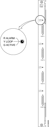
The NPM front card monitors its own activity. When a failure is detected, the fail LED is lit. In nodes with redundant NPMs, the active NPM is indicated by an active LED, while the standby NPM will not have a lit active LED (see Figure 2-2 ). To display information on any NPM from the switch software command-line interface (CLI), use the switch software dspcd command.
Table 2-1 describes NPM front card memory and memory expansion capability for all three NPM front card versions.The switch software image is stored in the dynamic RAM (DRAM), with non-volatile Flash electrically-erasable programmable ROM (EEPROM) supporting switch software image download over the attached network. Battery-backup RAM (BRAM) stores system configuration data.
In a nonredundant system, the NPM front card resides in either slot 1 or slot 2 (see the "Disabling NPM Redundancy" section for information on disabling NPM redundancy). In a redundant system with two NPM front cards, the front cards reside in slot 1 and slot 2. A utility bus in the backplane connects redundant NPMs.
Redundant NPMs have automatic failover, with the redundant card becoming active as soon as a failure occurs on the primary NPM. The failed NPM will report an alarm condition through the fail LED on the failed card's faceplate.
In automatic failover, configuration and operational information changes are shared by both cards as they occur.
NPMs are shipped with NPM redundancy enabled.However, if you have only one NPM installed in your chassis, your node will continue to report a minor alarm until you disable NPM redundancy on that node. To disable NPM redundancy, use the following procedure.
Step 2 At the switch software CLI, disable NPM redundancy with the switch software cnfnodeparm 16 n command.
Step 3 Log out of the IGX node.
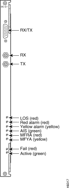
The system clock module (SCM) back card provides the main clock generation function for the IGX. The SCM phase-locks internal IGX timing to the selected clock source for network synchronization. The SCM also measures cabinet temperature and provides external interfaces for network management access to the node.
Each SCM has the following external interfaces (see Figure 2-3):
For a description of the SCM LEDs, see Table 2-2.
| LED | Color | Meaning |
|---|---|---|
An error has occurred. For information on troubleshooting the SCM, see the "Troubleshooting an IGX Node" section in the Cisco IGX 8400 Series Installation Guide. |
||
The power supply monitor connector allows you to connect an external power supply monitor. Pins 2 and 3 indicate the status of the power supplies. These pins are TTL binary logic signals, with a value of zero indicating a power supply failure and a value of one indicating normal power supply operation. To use the power supply monitor connector, you need a device that responds with a fail condition when a zero TTL logic level is present on pin 2 or pin 3.
 |
Caution Do not use the RJ-45 connector on the SCM back card to connect your PC or terminal to the IGX. Power from the power supply monitor connector will cause damage to your PC or terminal. |
The SCM has integrated, independently-operating internal clock circuitry and phase-lock loops, with one clock circuit operating system bus A and the other clock circuit off system bus B. If the system bus A fails, the SCM fails over to the system bus B clock circuitry and the fail LED will turn on. Node operations will not be affected by SCM back card fail over.
Lower-priority SCM circuits, such as external clock input, control and auxiliary connectors, and power supply, cabinet temperate, and fan monitoring circuits are not duplicated. Failure of lower-priority circuits does not cause a system failure, but the SCM reports an alarm.
Each operating IGX node must have an SCM. Removal of the SCM disrupts system operation. The SCM resides in back card slot 1 (for information on installing back cards, see the Installing the IGX chapter in the Cisco IGX 8400 Series Installation Guide ).
 |
Tip One SCM is sufficient to support redundant NPM front cards. |
The external clock connector is a 15-pin input designed to allow network synchronization signals from an EIA/TIA-422 external clock source. The external clock signal must be 1.544 MHz or 2.048 MHz.
The external clock source can be configured as a primary, secondary, or tertiary clock source.
Trunk or line inputs can also serve as a source for timing for the node. If no clock source is detected, the node will use the internal IGX clock (on the SCM) as the clock source for the node.
An external clock source can be connected to the SCM card using the external clock adapter cable. The external clock device can be either 1.544 MHz or 2.048 MHz EIA/TIA-422 square wave signals. Selection is made through software.
For information on configuring external clock sources for an IGX node, see the "Making External Clock Connections" section in the Cisco IGX 8400 Series Installation Guide.
The active and redundant NPMs must be installed in slots 1 and 2. The NPM front card and SCM back card use a standard IGX card installation (see the "Inserting the Cards" section in the Cisco IGX 8400 Series Installation Guide).
Primary management tasks include maintaining and upgrading the switch software and firmware images for the IGX node, monitoring alarm states, and collecting statistics. In addition, Cisco recommends exercising redundant NPMs occasionally using the switch software command, switchcc.
Switch software management tasks can be conducted through a network management station running a network management program, such as Cisco WAN Manager, or through using the switch software command-line interface (CLI).
Before upgrading the switch software on a node, confirm the compatibility of the switch software and the firmware image(s) found on the cards installed in the node. Some switch software upgrades may require an additional firmware upgrade on some or all of the cards installed in the node.
For information on switch software and firmware compatibility, see the Compatibility Matrix at http://www.cisco.com/kobayashi/sw-center/sw-wan.shtml.
|
Note If a firmware image upgrade is necessary for a card installed in the node, you may need to upgrade the card's firmware before upgrading the switch software image to avoid operational problems in your network. Check the firmware release notes for specific information on upgrade procedures. |
At least one node in a network should have a Cisco WAN Manager terminal, a control terminal, or a dial-in modem connected to it. Any control terminal connected in the network can configure, manage, monitor, and diagnose the entire network. In addition, at least one node in a network can have a connected printer for error and event reports.
The control terminal and printer connect to two EIA/TIA-232 serial ports. These ports are the control terminal and auxiliary port on the SCM faceplate. These serial ports support all standard asynchronous data rates from 1200 to 19,200 bps. The default rate is 9600 bps. Data rates and the type of equipment connected to the ports are software-configurable.
The IGX alarm interface module consists of an alarm relay module (ARM) front card and an alarm relay interface (ARI) back card.
The module performs the following major functions:
|
Note Alarm reporting through the alarm interface module is separate from alarm output to the node's control port which provides alarm data to a control terminal such as a CWM network management station. |
One set of alarm relays signals a major or minor alarm on the node, with one pair of contacts on each relay being used for audible alarms. The other set of relay contacts is used for visual alarms (see Table 2-5).
Table 2-5 Alarm Relay Module Alarm Reporting
| Type | Severity | Indicator | ARM Action |
|---|---|---|---|
Visual and audible form C relays are normally open or normally closed. |
|||
|
Tip To turn off audible alarms, use the faceplate alarm cutoff (ACO) switch. When the ACO switch is activated, a faceplate ACO indicator is lit as a reminder to the user. If the ACO switch is activated to disable the node's audible alarm output and a second alarm occurs, the audible alarm is re-activated. |
The ARM front card requires the ARI back card for proper functioning. Alarm relays are controlled by switch software through control bus commands. Because the ARM does not handle user data, there is no ARM connection to the cell bus.
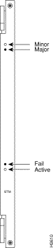
The ARM faceplate contains the alarm, active, and fail LEDs, and the ACO and history clear push buttons (see Figure 2-4 and Table 2-6).
The ARM periodically runs a background self-test to determine the state of the card. If the card fails this self-test, the faceplate fail LED turns on, and the active LED turns off.
The alarm relay interface (ARI) back card contains the alarm relays and their associated relay drivers. Alarm outputs are dry contact closures from form C relays. The user must supply the voltage source to be switched by the IGX. Any source or load can be switched if it meets the following requirements:
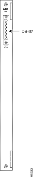
A female DB-37 connector resides on the faceplate for connection to the customer's office alarm or alarm-reporting system. For information on connector pinouts, see the "External Alarm Cabling" section in the Cisco IGX 8400 Series Installation Guide.
Refer to Figure 2-5 for an illustration of the ARI faceplate.
Enable alarm display functionality on the ARM with the switch software addalmslot command. The ARM requires standard management and preventive maintenance tasks.
To set up an ARM after installation, use the following procedure:
Step 2 Enter the switch software addalmslot slot command to activate alarm reporting from the card.
Step 3 Check the active LED on the front card faceplate.
Step 4 Test alarm output operation by creating an alarm on the node.
|
Tip Create an alarm by disconnecting a trunk cable from the connector on the back card. |
|
Caution To avoid disruption of necessary network traffic, do not generate a major alarm during periods of high network traffic. |
Step 5 Check that the major LED lights up on the front card faceplate of the ARM.
Step 6 Using a voltage/ohm meter (VOM), make sure continuity exists between pins 16 and 17 and between pins 35 and 36 at the DB-37 connector on the ARI card.
Step 7 Remove the alarm from the node by restoring the connection you disabled in Step 4.
Step 8 With the VOM, check that the reading between pins 16 and 17 and pins 35 and 36 are open and the major LED is not on.
Alarm output connections are made at the DB-37 connector on the ARI card. The connector pin assignments with the alarm signal names are listed in Table 2-7.
The following paragraphs describe the maintenance and troubleshooting features associated with the ARM card set. Preventive maintenance is not necessary.
Diagnostic routines periodically run to test the card's performance. These diagnostics run in the background and do not disrupt normal behavior. If a failure is detected during the self-test, the faceplate red fail LED turns on. In addition, you can check the status of the card by using the switch software dspcd command. If a card failure is reported, the report remains until cleared. To clear a card failure, use the switch software resetcd command.
There are two types of resets: hardware and failure. The reset failure clears the event log of any failure detected by the card self-test and does not disrupt card operation. The hardware reset reboots the firmware and resets the card, which momentarily disables the card.
Service modules allow configuring of data, voice, ATM, Frame Relay (FR), and IP services over the IGX node. In an operational network, multiple service cards may be installed in the same physical chassis, with many different possible configurations of service types, interface connector types, and transmission formats. These service modules can be used in any of the three chassis models. However, careful planning of slot space and cabling is important for easy and efficient maintenance and troubleshooting tasks.
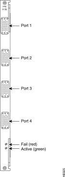
IGX service front cards and back cards have several standard indicator LEDs on their faceplates. While some cards may have additional LEDs, all cards have both a green active LED and a red fail LED located at the bottom of the faceplate.
Table 2-8 Standard IGX Service Card LEDs
|
Caution In order to contain electromagnetic interference (EMI) and radio frequency interference (RFI), and to ensure desired airflow for adequate chassis cooling, install a blank faceplate in any back card slots where no back card exists. |
Except where noted, IGX service modules use a standard installation procedure (see "Installing the IGX" in the Cisco IGX 8400 Series Installation Guide).
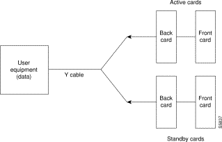
Except where noted, you can configure the service module for 1:1 redundancy by installing a second, identical card group in another slot. Use a Y-cable to connect the two redundant back cards, then use the switch software addyred command to add Y-redundancy to the card's configuration. See Figure 2-6 for an illustration.
The hardware kits for this feature usually contain a second, duplicate card set, a set of Y-cables to interconnect the two card sets, and any other pieces that apply to the card types. Y-cable redundancy is not possible using back cards with different interfaces, such as an FRI T1 and FRI V.35.
For specific information on advanced card configuration tasks, refer to the information for your specific front card and back card combination, or to "Installing the IGX" in the Cisco IGX 8400 Series Installation Guide.
The following paragraphs describe standard service module maintenance and troubleshooting features. Except where noted, preventive maintenance is not necessary.
When you connect an unsupported back card to the service module front card, the output from the switch software dspcds command informs you that you have a card mismatch.
Diagnostic routines periodically run to test the card's performance. These diagnostics run in the background and do not disrupt normal traffic. If a failure is detected during the self-test, the faceplate red fail LED turns on. In addition, you can check the status of the card by using the switch software dspcd command at the control terminal. If a card failure is reported, the report remains until cleared. To clear a card failure, use the switch software resetcd command.
There are two types of resets: hardware and failure. The failure reset clears the event log of any failure detected by the card self-test and does not disrupt card operation. The hardware reset reboots the firmware and resets the card, which momentarily disables the card.
Table 2-9 shows supported front and back cards for the network trunk module (NTM).
The NTM enables FastPacket transmission on a trunk established between two IGX nodes. NTM features include the following:
|
Note There are two variants of the NTM front card: one uses an ACM1 adapter to connect two legacy card designs and the other is a single card version built for the IGX chassis. While functionally identical, their firmware cannot be interchanged. The single-card NTM requires firmware revision F or later. |
An NTM front card can occupy any available front service card slot (slots 3 to 32). The module's back card depends on the desired trunk interface type. See the following usage information:
For a description of the NTM front card faceplate, see Figure 2-7.
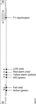
The NTM T1 interface back card (BC-T1) terminates a single 1.544 Mbps T1 trunk on the network trunk module in the IGX, and provides the following features:
The BC-T1 uses a DB-15 interface connector (see Figure 2-8) and has loss of signal and loss of FastPacket alignment indicators on the back card faceplate (see Table 2-10).
Table 2-10 BC-T1 Back Card Faceplate LEDs
The NTM E1 interface card (BC-E1) terminates an E1 trunk line on the NTM front card, and provides the following features:
Figure 2-9 and Table 2-11 provide descriptions of the BC-E1 status LEDs and connectors on the BC-E1 faceplate.
Table 2-11 BC-E1 Back Card LEDs
| LED | Meaning |
|---|---|
Loss of local frame alignment or FastPacket alignment on the local end. |
|
Loss of remote frame alignment or FastPacket alignment on the remote end. |
|
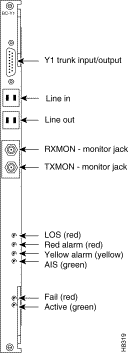
The NTM Y1 interface back card (BC-Y1) terminates a Y1 line on the NTM front card, and provides the following features:
Figure 2-10 and Table 2-12 provide descriptions of the BC-Y1 status LEDs and connectors on the faceplate.
The subrate interface back card (BC-SR) terminates subrate trunks on the NTM. The BC-SR provides the following features:
Because a subrate trunk facility interface operates in DCE mode with the subrate channel functioning like a synchronous data channel, the BC-SR back card always operates in DTE mode. Subrate trunks cannot pass clock signals, so you must make provisions for separate clock signalling sources for each IGX node connected to the network solely through subrate trunks (see the "Connecting an NTM E1 or Subrate Trunk" section in the Cisco IGX 8400 Series Installation Guide).
Table 2-13 BC-SR Back Card LEDs
| LED | Meaning |
|---|---|
Table 2-15 shows the front and back cards supported for the universal switching module (UXM and UXM-E).
Table 2-15 Universal Switching Module Front and Back Cards
|
Note Information for the enhanced universal switching module (UXM-E) also applies to the UXM. For differences between the two cards, refer to the release notes for your card. |
The enhanced universal switching module (UXM-E) provides ATM trunk and line service for the IGX. In trunk mode, the UXM-E supports network trunks and in port mode, the UXM-E supports either an ATM user-to-network interface (UNI) or a network-to-network interface (NNI). The back cards support multiple physical connector types, with ports operating at OC3/STM1, T3, E3, T1, or E1 rates.
The UXM-E can transport ATM cells to and from the IGX cellbus at a maximum rate of 310 Mbps in each direction. This maximum rate applies regardless of back card type.
Switch software limits the number of logical trunks and lines that can be configured on an IGX node as shown below:
These limits are independent of the number of UXM or UXM-E cards in the IGX switch chassis, because switch software monitors the number of configured lines and trunks, not the number of cards that are physically present.
When you reach these limits, switch software prevents activation of additional trunks or lines on the node, and you see an error message.
The UXM and UXM-E also support the following features for both trunk and port modes:
|
Note The UXM and UXM-E cannot support more than 4000 gateway connections. All remaining connections can be user or networking connections. For example, if you configure 2500 gateway connections onto a UXM-E, you still have 5500 possible user or networking connections. |
For information on initial configuration of a UXM-E, see the "UXM-E Configuration" section.
In trunk mode, the UXM-E supports up to 8000 connections. The UXM-E in trunk mode cannot support more than 4000 gateway connections. All remaining connections can be either user or networking connections. For example, if you configure 2500 gateway connections, you still have 5500 connections available to be used for networking connections.
Between the network and customer premise equipment (CPE), the UXM-E communicates only ATM cells. However, on the cellbus, the UXM-E communicates either ATM cells or FastPackets, depending on the destination card type.
Table 2-16 provides a summary of the traffic management features available on the UXM-E.
Table 2-16 Traffic Management Features Supported on the UXM-E
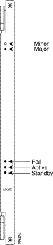
The UXM-E front card faceplate has five LEDs (see Figure 2-12). These LEDs indicate card status through different combinations of the fail, active, and standby LEDs. Use Table 2-17 during UXM-E troubleshooting (for more information on UXM-E troubleshooting, see the "UXM-E Troubleshooting" section).
| Fail LED | Active LED | Standby LED | Card Status |
|---|---|---|---|
The standby front card's self-test indicates a back card mismatch. |
|||
The UXM-E has many different back cards, providing support for various physical line and connector configurations. See Table 2-18 for more information.
For images of sample UXM-E back cards, see Figure 2-13, Figure 2-14, Figure 2-15, and Figure 2-16.
For technical information on the various physical line types, see the "UXM-E Physical and Electrical Specifications" section in the Cisco IGX 8400 Series Installation Guide.
Most UXM-E back cards have a tricolor LED for each line that indicates the status of the line. This tricolor LED is located above the physical connector for the line. See Table 2-19 for a description of the tricolor LED.
|
Note The T1 and E1 back cards do not have the standard service module active and fail LEDs to indicate card status. If a T1 or E1 back card failure is detected, all of the tricolor LEDs on the back card turn red. |
The appearance of UXM-E back card faceplates will vary based on the back card's physical line type, physical connector type, and number of physical connectors. See Figure 2-13, Figure 2-14, Figure 2-15, and Figure 2-16 for sample UXM-E back cards.
Figure 2-13 shows a BC-UAI-4-155-SMF back card faceplate. The following back cards have similar faceplates:
Figure 2-14 shows a BC-UAI-6-T3 back card faceplate. The following back cards have similar faceplates:
Figure 2-15 shows a BC-UAI-8-T1-DB-15 back card faceplate. The following back cards have similar faceplates:
Figure 2-16 shows a BC-UAI-8-E1 BNC back card faceplate. Each BNC connector carries traffic in only one direction. The BC-UAI-4-E1 has a similar faceplate.
|
Tip Switch software limits the number of logical trunks and lines that can be configured on an IGX switch. To optimize your chassis space, do not install more than 64 lines or 32 trunks (these totals include all lines or trunks available on all trunk or line modules in the chassis). Modules used for hot standby do not count toward these totals. |
The UXM-E uses a standard IGX card installation (see "Installing the IGX" in the Cisco IGX 8400 Series Installation Guide).
Like other IGX service modules, the UXM-E can be configured for Y-cable redundancy. Both cards, the primary and the redundant, must be installed before you configure them for Y-cable redundancy.
The UXM-E features hot standby, in which the redundant card receives card configuration information as soon as you finish specifying redundancy. The standby card also updates its configuration as the active card configuration changes.
For more information on setting up Y-cable redundancy, see the "Card Redundancy" section.
When you insert a new UXM-E into the backplane, or apply power to the IGX node, the UXM-E firmware reports the card type and the number of physical lines on the back card to the node's switch software.
|
Note On activation, the UXM-E reports the number and type of physical ports available on the attached back card. This back card configuration information is retained by switch software even if the back card is later removed. |
To activate a trunk, use the switch software uptrk command (see Chapter 4, "Cisco IGX 8400 Series Trunks").
To activate a line, use the switch software upln command (see Chapter 5, "Cisco IGX 8400 Series Lines").
Most UXM-E management tasks are general trunk or line management tasks. See Chapter 4, "Cisco IGX 8400 Series Trunks," or Chapter 5, "Cisco IGX 8400 Series Lines" for more information on managing and troubleshooting trunks or lines.
A UXM-E line or trunk can serve as the clock source for the IGX node. To configure the clock source, use the switch software cnfclksrc command. To display available clock sources, use the switch software dspclksrcs command. To show the current clock source, use the switch software dspcurclk command.
For more information about clocking on IGX nodes, see "Cisco IGX 8400 Series Nodes"
Before setting up y-redundancy on two UXM-E cards, make sure that VC merge feature support is enabled on both cards. Both cards must run the appropriate firmware to support the VC merge feature.
For more information on enabling VC merge on the IGX, see the "VC Merge on the IGX" section in "IP ServiceFunctional Overview."
|
Note VC merge on the IGX is not supported in releases preceding Switch Software Release 9.3.40. |
Switch software classifies UXM-E trunk statistics as physical or logical. See the following list of rules used to distinguish physical trunk statistics from logical ones:
The following switch software commands apply to statistics for physical lines within an IMA trunk:
Table 2-20 Trunk Statistic Classification on the UXM-E for Switch Software Release 9.3 or Later
| Trunk Statistic | Statistic Type |
|---|---|
You can configure bucket statistics through Cisco WAN Manager (CWM) for logical lines, ports, and channels (connections). Statistics configuration in CWM requires the TFTP mechanism. You can also enter commands on the CLI. Refer to the Cisco WAN Switching Command Reference for descriptions of the following commands:
Integrated alarms for the UXM-E consist of LOS, LOF, AIS, YEL, LOC, LOP, Path AIS, Path YEL, Path Trace, and Section alarms. The display for the dsplns command lists an alarm if the related event occurs. You can configure the event duration that qualifies and clears an alarm with cnflnparm.
You can configure the class, rate, and duration for setting and clearing of statistical alarms with the cnflnalm command. Refer to the description of cnflnalm in the Cisco WAN Switching Command Reference publication for a list of all possible line alarm types. The display for the dsplnerrs command shows data for existing alarms. To clear the statistical alarms on a line, use the clrlnalm command.
The UXM-E supports local and remote loopbacks. You can establish a local loopback on either a connection or a port. Remote loopbacks are available for connections only. No line loopbacks are available for the UXM-E.
|
Note Card mismatch is not reported when the front card is in standby. If the card becomes active and there is a mismatch condition, the UXM-E will report a card mismatch. |
The UXM-E uses a standard card mismatch notification for unsupported back cards.
If the front card was previously active, the UXM-E provides mismatch notification for supported back cards featuring a different line type than the previously-installed back card, or if the back card has a smaller number of the correct line types than what the UXM-E previously reported to switch software. Attaching a back card with more ports of the correct line types does not trigger a card mismatch. If the front card has not yet been activated, the UXM-E does not provide mismatch information for supported back cards because a supported back card mismatch has not occurred.
For card mismatch examples, see Table 2-21.
Table 2-22 shows the front and back cards supported by the universal voice module (UVM).
The universal voice module consists of a UVM front card and a universal voice interface (UVI) back card with physical connectors for T1, E1, or Y1 lines. The module supports channelized T1, E1, or Y1 lines carrying voice, data, or voice+data traffic. For information on the connections supported by the UVM, see Table 2-23.
UVM features include the following:
For more information on voice technology specifications, see the "UXM-E Physical and Electrical Specifications" section in the Cisco IGX 8400 Series Installation Guide.
Table 2-23 Connections Supported by the UVM
| 1All voice connections can be configured for fax or modem upgrades.
2In order to support CSACELP, the UVM must run UVM firmware Model D or later. To determine the firmware model running on the UVM, use the switch software dspcds command. |
|
Tip To configure more than 16 channels for LDCELP or CSACELP with G.729, you must configure the UVM to pass remaining time slots to a second UVM for processing through configuration of line pass-through. During line pass-through, one UVM port connects to user equipment and the other port connects to another UVM. For more information on line pass-through, see Chapter 7, "Cisco IGX 8400 Series Voice Service" |
Voice frequency compression ratios can be determined through selection of a kbps rate for the voice channel. For example, a 64 kbps voice channel does not compress voice traffic. A 32 kbps voice channel compresses voice traffic at 2:1. See Table 2-24, "Cisco IGX 8400 Series Voice Service" (Chapter 7), and the Cisco WAN Switching Command Reference for more information.
Table 2-24 Voice Compression Ratios According to Channel Transmission Rates
| Transmission Rate | Voice Compression Ratio |
|---|---|
Idle code suppression (ICS) allows bandwidth savings on an nx64 super-rate data connection used to carry video traffic conforming to the H.221 video codec frame protocol. The video channel is considered idle at any time when identical data occurs in relevant time slots for 256 consecutive T1, E1, or J1 frames. Depending on the data channel size, the number of consecutive identical bytes necessary to trigger idle code suppression can range from 256 to 2048 consecutive identical bytes.
To enable ICS on a data channel, use the switch software cnfdch command.
|
Tip In order to configure ICS on a data channel, the data channel must be used in an nx64 super-rate data connection that terminates on either a UVM or a CVM. |
The fax relay feature compresses the DS0 bit stream of a G3 fax connection to 9.6 kbps for transport through the IGX network. Fax relay on the UVM is supported for LDCELP and G.729 connections.
|
Note Fax relay on the UVM is not supported for connections using the G.729A standard (or PCM or ADPCM). |
After being enabled, fax relay overrides the automatic fax upgrade feature. However, a data modem will still upgrade to PCM or ADPCM. This automatic upgrade feature suspends compression when a modem or fax tone appears on a voice connection.
To configure a fax relay channel, use the switch software cnfchfax command.
A UVM front card can occupy any available front service card slot (slots 3 to 32). The module's back card depends on the desired line interface type. See the following usage information:
See Figure 2-17 for a description of the UVM front card faceplate.
The UVM has three different UVI back cards, providing support for various physical line types. See Table 2-25 for more information.
Table 2-25 Back Cards for the UVM
| 1When connecting E1 lines to the BC-UVI-2E1Ec, use either the two bi-directional DB-15 connectors or the uni-directional BNC connectors. |
Each physical connector on a UVI back card has a tri-color LED beneath it on the back card faceplate. The tricolor LED indicates the status of the port associated with that physical connector. See Table 2-26 for a description of the tricolor LEDs. See Figure 2-18 for a sample UVI back card.
|
Note The BC-UVI-2E1EC has an additional multiframe alignment LED associated with each physical connector. See Table 2-27 and Figure 2-19 for details. |
Table 2-27 The BC-UVI-2E1EC Multiframe Alignment LED
| Multiframe Alignment LED Color | Meaning |
|---|---|
The line has a loss of multiframe alignment at the remote end. |
To specify voice connections on the UVM, use either Cisco WAN Manager or the switch software CLI. For information on accessing the switch software CLI, see the "IGX Configuration Summary" section in the Cisco IGX 8400 Series Installation Guide . For more detailed information on switch software commands used to provision voice service, see "Cisco IGX 8400 Series Voice Service"
The UVM card set monitors and reports statistics on the following input line conditions:
Table 2-28 shows the front and back cards supported for the channelized voice module (CVM).
The CVM provides voice, data, and voice+data service for the IGX. Three different front cards and multiple back cards allow for users to select the configuration that best fits their networking environment.
The CVM supports the following features:
For more information on voice technology specifications, see the "Voice Circuit Support" section.
|
Note The CVM does not support LDCELP or CSACELP compression and cannot terminate a connection from a UVM if the connection uses LDCELP or CSACELP. |
Table 2-29 Connections Supported on the CVM
Voice frequency compression ratios can be determined through selection of a kbps rate for the voice channel. For example, a 64 kbps voice channel does not compress voice traffic. A 32 kbps voice channel compresses voice traffic at 2:1. See Table 2-30, "Cisco IGX 8400 Series Voice Service" (Chapter 7), and the Cisco WAN Switching Command Reference for more information.
Table 2-30 Voice Compression Ratios According to Channel Transmission Rates
| Transmission Rate | Voice Compression Ratio |
|---|---|
|
Tip Voice compression ratios approximately double when you enable internal VAD on that channel. |
Idle code suppression (ICS) allows bandwidth savings on an nx64 super-rate data connection used to carry video traffic conforming to the H.221 video codec frame protocol. The video channel is considered idle at any time when identical data occurs in relevant time slots for 256 consecutive T1, E1, or J1 frames. Depending on the data channel size, the number of consecutive identical bytes necessary to trigger idle code suppression can range from 256 to 2048 consecutive identical byes.
To enable ICS on a data channel, use the switch software cnfdch command.
|
Tip In order to configure ICS on a data channel, the data channel must be used in an nx64 super-rate data connection that terminates on either a UVM or a CVM. |
The CVM has three different front card options: standard CVM, CVM T1 EC, and CVM E1 EC.
The standard CVM supports the features listed in the "Channelized Voice Module" section. The CVM T1 EC features on-board echo cancelling circuitry for T1 lines. The CVM E1 EC features on-board echo cancelling circuitry for E1 lines.
The CVM has three different back cards. Please refer to the "CVM Front Cards" section for compatibility requirements.
The BC-T1 back card provides a T1 line interface for a CVM front card. The BC-T1 back card has the following features:
See Figure 2-20 for a description of the BC-T1 back card faceplate.
The BC-E1 back card provides one E1 line interface for a CVM. The BC-E1 has the following features:
See Figure 2-21 for a description of the BC-E1 back card faceplate. The BC-E1 back card has an additional multiframe alignment LED. See Table 2-31 for details.
Table 2-31 BC-E1 Multiframe Alignment LED
| Multiframe Alignment LED Color | Meaning |
|---|---|
The line has a loss of multiframe alignment at the remote end. |
The BC-J1 back card provides a Japanese J1 circuit line interface for a CVM. The BC-J1 has the following features:
See Figure 2-22 for a description of the BC-J1 back card faceplate. The BC-J1 back card has an additional multiframe alignment LED. See Table 2-32 for details.
Table 2-32 BC-J1 Multiframe Alignment LED
| Multiframe Alignment LED Color | Meaning |
|---|---|
The line has a loss of multiframe alignment at the remote end. |
Table 2-33 shows the front and back cards supported for the universal frame module (UFM).
The UFM provides Frame Relay (FR) service across a connection between two IGX nodes. The module supports ELMI and Frame Relay-to-ATM service interworking, and can support FR traffic through T1, E1, V.35, X.21, or HSSI interfaces.
There are three front cards in the UFM card set. See the "UFM-C Front Cards" section for more information about the two UFM-C front card models, and see the "UFM-U Front Card" section for information on the UFM-U front card. See Table 2-33 for information on front and back card compatibility.
The following cards can terminate connections from a UFM:
|
Note For connections with an endpoint on a Cisco MGX 8200 series platform, refer to either MGX 8220 or MGX 8250 documentation, as appropriate. |
The UFM supports the following features:
|
Note Logical ports must use contiguous time slots. See the "Making Frame Relay Connections" section in the Cisco IGX 8400 Series Installation Guide for more information. |
The UFM-C front cards can occupy any available front service card slot (slots 3 to 32). The module's back card depends on the desired interface type; please see the following usage information:
The UFM-C front cards support either four (the UFM-4C) or eight (the UFM-8C) T1 or E1 lines per back card. See Figure 2-23 for a description of a UFM-C front card faceplate. The UFM-C front cards use standard service card LEDs; see the "Standard Service Module LEDs" section for more information on these LEDs. For information on back cards compatible with the UFM-C, see Table 2-33.
|
Note Actual data throughput on the card depends on hardware and on frame size. As the frame size decreases, throughput will decrease. For example, a frame size of 100 B results in a sustainable throughput of 16.384 Mbps. With 60 B frames, a throughput of 16.384 Mbps can result in data loss. |
|
Tip UFM-8C front cards are simply labeled "UFM-C" while UFM-4C front cards are labeled "UFM-4C." |
A UFM-U front card can occupy any available front service card slot (slots 3 to 32). The module's back card depends on the desired port type; see the following usage information:
In addition to features supported by the UFM-C (see the "UFM-C Front Cards" section), the UFM-U front card has the following features:
The aggregate port speed configurable across all ports is 24.576 Mbps. This speed is the maximum line speed and the over-subscription ceiling.
The UFM-U front card allows you to specify active ports and to set the maximum speed allowed on each active port. See the "UFM-U Configuration" section for more information. Figure 2-24 shows the UFM-U front card faceplate.
Because of hardware constraints, the UFM-U does not permit random combinations of speeds across active ports. Configuring active ports on the UFM-U requires that you use certain specified combinations (called modes) of maximum rates on these active ports.
|
Note Specifying the maximum speed for active ports requires careful planning, so read the following information before attempting to configure your UFM-U active ports. To specify active ports and the maximum speed allowed on each active port, see the "Initial Configuration of the UFM-U" section. |
Active ports on the UFM-U are grouped into port groups, which are indicated by alphabetic names. For example, Group A consists of ports 1 through 4 on the V.35 and X.21 back cards, and ports 1 and 2 on the HSSI back card. Group B consists of ports 5 through 8 on the V.35 and X.21 back cards, and ports 3 and 4 on the HSSI back card. Group C consists of ports 9 through 12 on the V.35 and X.21 back cards; the HSSI back card does not have a Group C.
 |
TimeSaver Specify your desired mode before you add connections to the card to avoid having to delete some or all of your connections and down your active ports before changing the mode. For information on changing the mode, see the "Configuring UFM-U Modes" section. |
To configure your UFM-U on initial power-on of the module, use the following procedure:
Step 2 Select the appropriate mode for the card, based on desired maximum throughputs for each port group.
Step 3 Configure port speeds with the switch software cnfport command. For each port to be activated, set the port speeds at or below the maximum throughput shown in Table 2-34 and Table 2-35.
Step 4 Activate the appropriate ports for each port group with the switch software upport command.
Step 5 Add connections to the UFM-U with the switch software addcon command.
When configuring your active ports and selecting your mode, remember the following two rules:
When calculating your maximum throughput, you must add the maximum bit rate for each port in the port group to find the maximum group throughput before calculating the maximum throughput for the card.
Table 2-34 shows the maximum bit rate per port on the V.35 or the X.21 back card for each available mode. Table 2-35 shows the maximum bit rate per port on the HSSI back card for each available mode.
|
Note In Table 2-34 and
Table 2-35, the following abbreviations
are used to reflect switch software command syntax: 3 = 3 Mbps = 3072 kbps 8 = 8 Mbps = 8192 kbps 10 = 10 Mbps = 10240 kbps |
Table 2-34 Bit Rates for Each Port in Specified Mode (for V.35 and X.21 Back Cards)
| Mode | Port 1 | Port 2 | Port 3 | Port 4 | Port 5 | Port 6 | Port 7 | Port 8 | Port 9 | Port 10 | Port 11 | Port 12 |
|---|---|---|---|---|---|---|---|---|---|---|---|---|
Table 2-35 Bit Rates for Each Port in Specified Mode (for HSSI Back Card)
| Mode | Port 1 | Port 2 | Port 3 | Port 4 |
|---|---|---|---|---|
Before changing the mode on a UFM-U, you must first determine whether the mode change will cause any changes in the maximum port speeds of any active ports. If the maximum port speed on an active port will change because of a mode change, you must first delete all connections in that port's port group and down all active ports in that port group before changing the mode.
For example, if you have connections on ports 1, 3, and 9 through 12 in mode 1 and you want to change to mode 4, you must first delete all connections on ports 1 and 3, then down ports 1 and 3 before changing to mode 4.
If you have connections on ports 1, 3, 5, 7, 9, and 11 in mode 2 and you want to change to mode 9, you must first delete connections on ports 1 and 3, then down ports 1 and 3 before changing to mode 9. After changing to mode, you must reestablish all of your connections on port 1 only.
|
Note If you do not have connections on a port in the port group but the port has been upped, you must still down all ports in the port group before changing the mode. |
See the "Changing the Mode on a UFM-U" section for information on how to change modes on the UFM-U.
To change modes on a previously-configured UFM-U, use the following procedure:
Step 2 Deactivate all active ports in port groups where the maximum ports speeds will change with the switch software dnport command.
Step 3 Using the switch software cnfport command, configure new port speeds for all appropriate ports in any port group where maximum port speed changes will occur due to the mode change.
Step 4 Change the mode on the UFM-U with the switch software cnfmode command.
Step 5 Activate all necessary ports for the new mode with the switch software upport command.
Step 6 Add necessary connections to the UFM-U with the switch software addcon command.
|
Note The UFI-8T1-DB-15 back card is compatible with the UFM-4C and UFM-8C front cards. It is not compatible with the UFM-U front card. |
The UFM back card shown in Figure 2-25 has eight bidirectional, DB-15 connectors. For each line, one tricolor LED displays the status of the line using that connector (see Table 2-36). If the LED is off, the line is inactive.
Table 2-36 UFI-8T1-DB-15 Port LEDS
| LED | Function |
|---|---|
The line for the connector below the LED is active, but a local alarm has been detected. |
|
The line for the connector below the LED is active, but a remote alarm has been detected. |
|
Note The UFI-8E1-DB-15 and UFI-8E1-BNC back cards are compatible with the UFM-4C and UFM-8C front cards. They are not compatible with the UFM-U front card. |
There are two different E1 back cards available for the UFM—the UFI-8E1-DB-15 and the UFI-8E1-BNC. The UFI-8E1-DB-15 has eight bidirectional DB-15 connectors, and the UFI-8E1-BNC has 16 BNC connectors (two per port, with one transmit connector and one receive connector). See Figure 2-26 for a description of these two back card faceplates. For each line, one tricolor LED displays the status of the line using that connector (see Table 2-36). If the LED is off, the line is inactive.
Table 2-37 UFI-8E1-DB-15 and UFI-8E1-BNC LEDs
| LED | Function |
|---|---|
The line for the connector below the LED is active, but a local alarm has been detected. |
|
The line for the connector below the LED is active, but a remote alarm has been detected. |
|
Note The UFI-12.V35 back card is compatible with the UFM-U front card. It is not compatible with either the UFM-4C or the UFM-8C front cards. |
The UFI-12V.35 back card in Figure 2-27 for the UFM-U front card has six connectors, with each connector carrying two V.35 ports. Each port in the connector has an associated LED for indicating port state. See Table 2-38 for more information on these LEDs.
To use the UFI-12V.35 back card in DTE mode, use the V.35-DTE cable to connect the back card to DCE interfaces. For more information on the cables used with the UFI back cards, see the "UFM Cabling" section in the Cisco IGX 8400 Series Installation Guide.
|
Tip Each port on the UFI-12V.35 can be configured to support either normal clocking or loop timing. For more information on port configuration, see the "UFM-U Configuration" section. |
| LED | Function |
|---|---|
The port is active and functional (to determine the LED for a specific port, refer to the label on either side of the physical connector). |
|
|
Note The following port speeds are supported on the UFI-12V.35 back card: 56, 64, 112, 128, 168, 192, 224, 256, 320, 336, 384, 448, 512, 640, 672, 768, 896, 960, 1024, 1280, 1344, 1536, 1920, 2048, 3072, 4096, 5120, 6144, 7168, 8192, 9216, and 10240 kbps. |
|
Note The UFI-12X.21 back card is compatible with the UFM-U front card. It is not compatible with either the UFM-4C or the UFM-8C front cards. |
The UFI-12X.21 back card in Figure 2-28 for the UFM-U front card has six connectors, with each connector carrying two X.21 ports. Each port in the connector has an associated LED for indicating port state. See Table 2-39 for more information on these LEDs.
|
Tip To use the UFI-12X.21 back card in DTE mode, use the X.21-DTE cable to connect the back card to DCE interfaces. For more information on the cables used with the UFI back cards, see the "UFM Cabling" section in the Cisco IGX 8400 Series Installation Guide. |
| LED | Function |
|---|---|
The port is active and functional (to determine the LED for a specific port, refer to the label on either side of the physical connector). |
|
|
Note The following port speeds are supported on the UFI-12X.21 back card: 56, 64, 112, 128, 168, 192, 224, 256, 320, 336, 384, 448, 512, 640, 672, 768, 896, 960, 1024, 1280, 1344, 1536, 1920, 2048, 3072, 4096, 5120, 6144, 7168, 8192, 9216, and 10240 kbps. |
|
Note The UFI-4HSSI back card is compatible with the UFM-U front card. It is not compatible with either the UFM-4C or the UFM-8C front cards. |
The UFI-4HSSI back card in Figure 2-29 for the UFM-U front card has four connectors. Each connector has a tri-color status LED (see Table 2-40). Each connector corresponds to one port. For information on configuring these ports, see the "UFM-U Configuration" section.
|
TimeSaver Interfaces on the UFI-4HSSI back card are already in DCE mode (default) so you can directly connect any DTE interface to the back card using a straight pin-to-pin HSSI standard cable. |
|
Tip The UFI-4HSSI back card can be configured in DTE mode by using the HSSI-DTE cable to connect back cards in DTE mode to DCE interfaces. For more information on the cables used with the UFI back cards, see the "UFM Cabling" section in the Cisco IGX 8400 Series Installation Guide. |
| LED | Function |
|---|---|
The port is active and functional (to determine the LED for a specific port, refer to the label on either side of the physical connector). |
|
Table 2-41 shows the front and back cards supported for the Frame Relay module (FRM).
|
Note The Frame Relay module (FRM) is no longer available for sale through Cisco Systems, Inc. However, the card set is supported in Switch Software Release 9.3.30 or later to allow legacy users to migrate their networks into the current switch software release. If you have questions regarding the availability of the FRM, contact your Cisco account representative (see "Obtaining Technical Assistance" section on page xiv for information on contacting Cisco if you do not have an account representative). |
The FRM provides FR support for the IGX chassis, and supports the following features:
Firmware on the FRM front card must match the interface type found on the back card. See Table 2-42 for compatibility information. Use the switch software command, dspcd, to view the type of back card supported by your current FRM firmware.
Table 2-42 FRM Firmware Compatibility and Supported Interfaces
| Front Card Firmware | Supported Back Cards | Supported Interface Types |
|---|---|---|
|
Note FRM front cards exist in two forms. One uses an ACM1 adapter. The other is a single-card or "native" version. Functionally, they are identical. For the single-card version, you must use FRM firmware version V or later. |
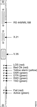
Both the Frame Relay interface V.35 (FRI-V.35) and X.21 (FRI-X.21) back cards provide the FRM with interfaces to user equipment. The FRI-V.35 provides four V.35 interfaces, and the FRI-X.21 provides four X.21 interfaces. Port operating rates and composite data rates for the two interface types are the same, and most configuration tasks require the same procedures.
For a description of the FRI-V.35 back card faceplate, see Figure 2-30. For a description of the FRI-X.21 back card faceplate, see Figure 2-31.
The Y-cable redundancy kits for the FRI-X.21 and FRI-V.35 contain four extra daughter cards for specifying individual ports as either DCE or DTE. The extra daughter cards are 200-ohm versions for the FRI already installed. The higher impedance cards are necessary to maintain proper termination impedance when the two interfaces are in parallel (by way of the Y-cable).
You can configure the port (DCE or DTE) on an FRI back card using the position of a jumper card on the back card. See the "Preparing the Cards" section in the Cisco IGX 8400 Series Installation Guide for more information.
For more information on the FRI-V.35 back card, see the "FRI-V.35 Back Cards" section. For more information on the FRI-X.21 back card, see the "FRI-X.21 Back Card" section.
Both models of the FRI-V.35 have the following functions and features:
For a description of the back card faceplate, see Figure 2-30.
The FRI-X.21 back card has the following features:
For a description of the back card faceplate, see Figure 2-31.
Most configuration tasks for the FRM follow standard IGX module configuration procedures. However, the FRM with FRI-V.35 back card differs in the effect that module firmware models and number of operating ports has on maximum throughputs for each port, and in the way the FRI-V.35 back card handles data clocking. For information on calculating maximum throughput for your specific usage situation, see the "Calculating Maximum Throughput for Different FRM Firmware Combinations" section. For more information on data clocking on the FRI-V.35 back card, see the "Data Clocking on the FRI-V.35 Back Card" section.
The maximum throughput for the FRM using the FRI-V.35 back card depends on the number of activated ports (see Table 2-43).
Table 2-43 Maximum Throughputs with the FRI-V.35 Back Card
| Maximum Throughput with 1 Port | Maximum Throughput with 2 Ports | Maximum Throughput with 3 Ports | Maximum Throughput with 4 Ports |
|---|---|---|---|
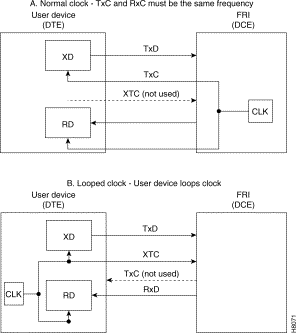
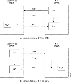
The FRI-V.35 back card supports both normal and looped clocking modes. However, the direction for clock and data flow will differ, depending on whether the FRI-V.35 back card is configured as DCE or DTE. Use the following rules to determine how clocking is conducted in different clocking modes:
See Figure 2-32 for a visual description of these two clocking modes.
|
Note In looped clocking, the clock is looped by the FRI-V.35 back card, not the connected user device. |
For ports configured for DTE, local and remote loopback port tests are also available. In test mode, the card transmits a loopback data pattern to initiate the loopback. Attached modems or NTUs might or might not recognize the loopback initiation pattern. If the modem or NTU does not recognize the loopback initiation pattern, the modem or NTU will not perform the requested loopback. The FRI waits a programmable time period (default=10 seconds) before sending the test pattern. After the test is completed, pattern transmission terminates and the circuit returns to normal operation.
Some external equipment supports loopback testing but does not recognize the test pattern (Test Mode) in the data stream. In these cases, the FRM/FRI toggles the V.35 local loopback (LLB) and the remote loopback (RLB) leads then runs the test pattern. The FRM/FRI still waits the user-specified time (default=10 seconds) before running the data test pattern.
To display test results, use the switch software tstport command.
FRI configuration supports one to four ports. The configuration depends on the maximum speed requirement (the card itself has a maximum composite speed).
|
Note The following port speeds are supported on the FRM with FRI-X.21 back card: 56, 64, 112, 128, 168, 192, 224, 256, 320, 336, 384, 448, 512, 640, 672, 768, 896, 960, 1024, 1280, 1344, 1536, 1920, and 2048 kbps. |
Unlike the FRI-V.35, the FRI-X.21 only supports normal clock mode. Depending on the configuration of the FRI, the direction of the clock and data lines may be reversed according to the following rules (see Figure 2-33):
To test FRI-X.21 back card ports and any associated external modems, CSUs, or NTUs, set up data loopback points in the circuit path using one of the following loopbacks:
To set up a loopback test, use the switch software tstport command. You can only test one port in loopback mode at a time.
|
Tip Any modem being used to test FRI-X.21 back card ports must be compatible with Cisco loopback protocols. For more information on these protocols and on supported modems, see Appendix A, "System Specifications", in the Cisco IGX 8400 Series Installation Guide or refer to the Cisco WAN Switching Command Reference for protocol requirements for the switch software commands addextlp, addloclp, and addrmtlp. |
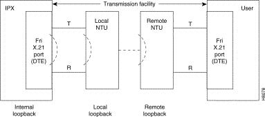
The internal loopback point is established inside the FRI-X.21 back card, as shown in Figure 2-34. The FRM front card generates a test pattern, sends the test pattern out on the transmit circuitry, and detects the returned pattern on the receive circuitry.
|
Tip To avoid disruptions in service, conduct loopback tests during periods of low network traffic. The test takes several seconds and will momentarily interrupt traffic on the port. |
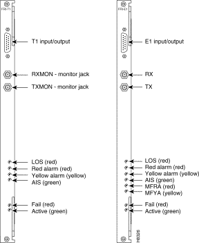
The FR interface T1 and E1 back cards (the FRI-T1 and FRI-E1) are one-line back cards with either a T1 or E1 interface, for use with the channelized FRM front card (Models E or J). For a description of the back card faceplates, see Figure 2-35. For a definition of the faceplate LEDs, see Table 2-44.
Table 2-45 shows the front and back cards supported for the high-speed data module (HDM).
Table 2-45 High-Speed Data Module Front and Back Cards
| Front Card | Back Cards |
|---|---|
SDI, EIA/TIA-449 (for X.21 also) |
The HDM consists of an HDM front card and a synchronous data interface (SDI) back card. There are three different models of the SDI back card, depending on the desired interface type (see Table 2-45 and Table 2-47). Depending on the chassis type, the IGX can support up to 29 HDMs for up to 232 full-duplex data connections.
The HDM supports the following features:
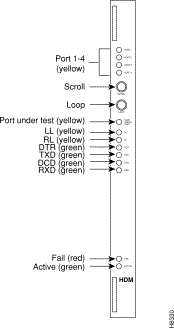
The HDM front card faceplate shown in Figure 2-36 has both LEDs and control buttons to assist with loopback control and signal monitoring tasks. See Table 2-46 for more information about the HDM front card faceplate LEDs and the "HDM Control Buttons" section for more information on HDM front card faceplate control buttons.
Table 2-46 HDM Front Card Faceplate LEDs
The HDM front card faceplate has two control buttons used to assist monitoring tasks (see Figure 2-36). The scroll control button allows you to select one of the four data ports on the SDI back card for monitoring. Information displayed by the front card faceplate LEDs applies to the selected back card data port only.
For example, if you use the scroll control button to select data port 1 (which has a local loopback present), the port 1 and LL LEDs will come on. If you use the scroll control button to select data port 4 (which has a transmit data signal), the port 4 and TXD LEDs will come on.
The loopback control button allows you to select one of three different loopback states (no loopback, local loopback, or remote loopback) for the selected port. For example, if port 1 is lit and you use the loopback control button to specify local loopback, the port under test LED and the LL LED will become lit to indicate that data port 1 now has a local loopback present.
The SDI back card provides data connections for the HDM front card. Each SDI back card model has four connectors with the connector type depending on the interface supported by the back card (see Table 2-47). Each connector provides the physical interface for one data ports. These data ports correspond to the Port LEDs of the same number on the HDM front card faceplate (see Figure 2-36). Each port is separately configurable.
Table 2-47 SDI Back Card Models by Interface and Connector Types
| SDI Back Card | Interface Type | Physical Connector |
|---|---|---|
You can use three different clocking modes on the SDI back card for clocking transmit data and receive data. Since the SDI back card can operate as either a DCE or a DTE, six different clocking combinations are possible (see Figure 2-37 and Figure 2-38 ).
Table 2-48 shows the front and back cards supported for the low-speed data module (LDM).
The LDM consists of an LDM front card and a low-speed data interface (LDI) back card. There are two LDI variants, depending on the desired number of ports (see Table 2-50).
The LDM card is a low-speed data module for use on EIA/TIA-232 ports with data rates up to 56 bps (4-port back card) or 19.2 kbps (8-port back card), where the higher speeds of an HDM are unnecessary. The low-speed data module (LDM) front card supports up to eight synchronous data ports. Each port can be independently configured for DTE or DCE mode, baud rate, and other parameters.
The LDM front card has the following features:
The LDM front card can reside in any empty front slot and requires an LDI back card.
The faceplate of the LDM front card has LEDs and buttons for loopback control and signal monitoring. Figure 2-39 shows and Table 2-49 lists these LEDs and buttons. The buttons are for loopback testing and scrolling through the data ports to obtain a snapshot of selected port conditions (indicated by port, port under test, loopback, and communication line status lights).
Table 2-49 LDM Front Card Connections and LEDs
Redundancy for LDM data card types is available through a second front and back card set and a Y-cable connection on each port to the customer data equipment. For more information on Y-cable redundancy, see the "Card Redundancy" section.
The 4- and 8-port LDM supports only a subset of the full EIA/TIA-232C/D control leads. The LDM supports only nonisochronous DCE normal and DTE looped clocking modes, transmission of 3 EIA lead states (non-interleaved), and baud rates of up to 19.2 kbps on the 8-port version and 56 kbps on the 4-port version. Split clock mode is not supported.
The low-speed data interface (LDI) back card is a low-speed data interface back card that operates in conjunction with an LDM front card. The LDI back card provides the physical and electrical connection interface between the user low-speed data circuit and the LDM data PAD. There are two LDI models—one 4-port and one 8-port (see Table 2-50).
The LDI back card has the following features:
The LDI back card can operate either as a DCE or DTE. Selection is made by using a Cisco DTE or DCE adapter cable between the port connector and the cable from the user device. This cable is terminated with a standard DB-25 on the customer end. Each port is configured separately.
Three EIA control leads are brought out to the rear connectors (see Table 2-51).
You can use remote loopback (RL) to enable a far-end modem loopback. Local loopback (LL) is not provided as an output on the LDI back card.
The LDI back card supports two clocking modes: normal and looped (see Figure 2-40). The normal mode is used when the LDI port is configured as a DCE. Looped clock is only used when the LDI port is configured as a DTE. The user device must take the external transmit clock and loop it back to the RxC for clocking in the receive data. In both cases, the LDI is the source of clock timing.
Table 2-52 shows the front and back cards supported for the universal router module (URM).
The URM delivers high-density voice interfaces, Fast Ethernet connectivity and ATM switching through a combination of Cisco IOS software and switch software functionality.
|
Note Refer to the Compatibility Matrix for Cisco IOS software, switch software, and firmware compatibility requirements. |
The URM consists of a logically-partitioned front card connected to a universal router interface (URI) back card. The front card contains an embedded UXM-E running an Administration firmware image, and an embedded router (based on the Cisco 3660 router) running a Cisco IOS image. The embedded UXM-E and the embedded router connect through a logical internal ATM interface, with capability equivalent to an OC3 ATM port.
|
Note Switch software treats this interface as an OC3 ATM port, and this interface is the only port on the embedded UXM-E that is visible to switch software. |
Unlike the Cisco 3660 router, which has one slot for the motherboard and six slots for network modules, the embedded router has three virtual slots with built-in interfaces (see Table 2-53 and Figure 2-41).
Table 2-53 Interfaces on Embedded Router Virtual Slots
Because the URM front card contains both an embedded UXM-E and an embedded Cisco router, the front card runs two separate software images with two different download procedures. For the embedded UXM-E, the administration firmware image is downloaded and saved to the embedded UXM-E Flash memory through switch software commands (see Cisco WAN Switching Command Reference ).
The embedded router runs Cisco IOS software. You can download and save the Cisco IOS image using standard Cisco IOS procedures as outlined in any documentation supporting the Cisco IOS image being used on the node.
The embedded UXM-E hardware is based on the UXM-E card for the Cisco IGX series and features 16 MB asynchronous DRAM, 8 MB Flash memory, and 8 KB BRAM. The embedded router hardware is based on the Cisco 3660 modular-access router and features 8 MB boot Flash SIMM, 32 MB Cisco IOS Flash SIMM, and 128 KB NVRAM.
Table 2-54 URM Hardware Components and Related Software
To locate different LEDs on the URM front card faceplate, see Figure 2-42. Refer to Table 2-55 for a description of the LED function.
Table 2-55 URM Front Card Faceplate LEDs
The BC-URI-2FE2VT1 and BC-URI-2FE2VE1 back cards provide T1 or E1 digital voice interfaces for the URM. BC-URI-2FE2V features include:
See Figure 2-43 to locate LEDs and interfaces on the URM back card. See Table 2-56 for a description of the physical ports on the back card, Table 2-57 for a description of the LEDs on the URI back card, and Table 2-58 for a description of the LEDs located on the installed VWIC.
Different URIs are made by inserting the appropriate VWIC into the basic BC-URI-2FE2V back card. Two VWICs can be used: the VWIC-2MFT-T1 for T1 connections and the VWIC-2MFT-E1 for E1 connections.
The VWIC-2MFT is a generic dual port T1 (VWIC-2MFT-T1) or E1 (VWIC-2MFT-E1) digital voice interface in a combined voice and WAN interface card (VWIC) for voice applications. VWIC-2MFT provides the following services for T1 or E1 networks:
At the physical layer, the VWIC provides two network interfaces through RJ-48C jacks with on-card TDM drop-and-insert capability, supported through router Cisco IOS reload operations. Because of the TDM backend, the VWIC is used as the front end for applications supporting channelized T1 and E1 services for voice.
|
Note For details on the VWIC T1 and E1 cards for voice connections, see the Cisco WAN Interface Cards Hardware Installation Guide. |
Table 2-56 BC-URI-2FE2V T1 and BC-URI-2FE2VE1 Connections
Table 2-57 LEDs for the BC-URI-2FE2VT1 and BC-URI-2FE2VE1
The BC-URI-2FE back card supports data traffic for the URM front card. The BC-URI-2FE supports the following features:
For a description of the BC-URI-2FE back card, see Figure 2-44. For information on the back card LEDs, see Table 2-59.
|
Tip Configuring the URM requires previous knowledge of both switch software and Cisco IOS software. Refer to both switch software and Cisco IOS documentation while configuring the URM (see the "Accessing User Documentation" section). |
Initial URM configuration differs from other IGX cards because you must perform configuration tasks by accessing two different software programs through two different CLIs.
Depending on your network setup, you can perform initial configuration either remotely through remote router configuration (RRC—see the "Initial URM Configuration Using RRC" section) or through a direct connection between your terminal and the URM card (made through the CON port on the back card—see the "Initial URM Configuration Using the Console Port" section).
If you do not have access to a TFTP server, or wish to configure the URM through a direct connection, use the following procedure:
Step 2 Verify that the URM is in standby with the switch software dspcds command.
Step 3 (Optional) Verify the following default configuration information with the switch software cnfrtr command:
|
TimeSaver Configure both parameters at the same time with the switch software cnfrtr slot n 1 command. |
|
Note If you reconfigure the URM to load the Cisco IOS configuration from NVRAM, the router enters the Cisco IOS setup utility. |
Step 4 Create the internal ATM port with the switch software addport command. The addport slot.1 command activates the embedded UXM-E and powers on the embedded router.
|
Note By default, the URM's internal ATM interface is a UNI port with a maximum bandwidth of 353,208 calls per second (cps) (equivalent to an OC-3 ATM port); the interface cannot be configured as a NNI port. |
|
Note If you have not connected a terminal to the CON port on the back card, you will not see the embedded router's initial start-up screens (see the "Cisco IOS Software Commands for the URM" section for an example startup screen). |
Step 5 (Optional) Configure the internal ATM port to support ILMI with the switch software cnfport command.
|
Note The port does not support LMI management protocol and should be configured to support either ILMI or none. If ILMI is not configured on the internal ATM port, the embedded UXM-E does not discover the assigned IP addresses for the URM card. |
Step 6 Activate the internal ATM port with the switch software upport command.
Step 7 Configure ATM connections onto the embedded UXM-E with the switch software addcon command. For more information on configuring ATM connections, see Chapter 8, "Cisco IGX 8400 Series ATM Service"
|
TimeSaver If you want the Cisco IOS configuration to load from NVRAM in the future, use the switch software cnfrtr slot r command at the switch software CLI. |
Step 8 Connect a dedicated console to the URM through the serial port (CON) located on the back card (see Figure 2-43).
|
Note For additional methods of accessing the URM Cisco IOS CLI, see the section "URM Cisco IOS CLI AccessSwitch Software Release 9.3.x and Earlier Releases" and the "URM Cisco IOS CLI AccessSwitch Software Release 9.4.0 and Later Releases" section. |
Step 9 (Optional) Use the Cisco IOS show version command to view information presented in the embedded router's initial startup screens.
Step 10 (Optional) To enter the Cisco IOS setup utility for basic configuration information, use the Cisco IOS setup command.
|
TimeSaver Perform remaining configuration tasks with RRC. See the "Initial URM Configuration Using RRC" section. |
Step 11 Configure an IP address onto the internal ATM interface by running the Cisco IOS command ip address command in the embedded router's interface configuration mode.
|
TimeSaver Cisco IOS software does not automatically save configuration changes to the embedded router NVRAM. To avoid losing configuration changes, use the Cisco IOS copy run start command to save copies of your Cisco IOS running configuration to the embedded router NVRAM while you are working. |
Step 12 Connect the management network with the embedded router through an IP-based protocol (such as Telnet, FTP, or TFTP). When connected, the embedded router reports assigned IP addresses to the embedded UXM-E through an ILMI topology discovery.
|
Tip Use the IP address configured on the internal ATM interface as the endpoint for a management VC between the URM and the management network. |
|
Note For ILMI to discover and display the IP address, the internal ATM interface must have a configured IP address and ILMI must be configured on the internal ATM port. The ILMI protocol does not exchange any other IP addresses with the IGX. |
Step 13 To configure ports on the URM, use Cisco IOS CLI commands. For more information on how to access Cisco IOS software documentation, see the "Accessing User Documentation" section.
Step 14 Configure voice connections on the URM using Cisco IOS CLI and switch software CLI commands. For more information, refer to switch software or Cisco IOS documentation listed in the "Accessing User Documentation" section.
The following differences between the two operating systems can impact connection setup:
Cisco IGX allows a UNI specified range of 0 to 65535. However, the embedded router has a VCI range of 0 to 1023, so you cannot terminate connections with a VCI value greater than 1023 on the URM. The ATM PVCs configured onto the embedded router must correspond to the WAN connections configured onto the embedded UXM-E. If the two sides of a connection are inconsistent, try checking the traffic parameter values for each side to see if they are different, then redefine each value so that they are consistent.
|
Note The PVC with the address vpi.vci 0.1023 on the URM internal ATM port is reserved and is not available to the user. |
Step 15 Save configuration changes to the embedded router NVRAM using the Cisco IOS copy run start command.
Step 16 If you have not already done so, reconfigure the embedded router to load the Cisco IOS configuration from NVRAM in the future using the switch software cnfrtr slot r command at the switch software CLI.
|
Tip After you have configured the embedded router, set up an external TFTP server to back up your Cisco IOS configuration. Use the Cisco IOS copy nvram tftp://host address/destination file command to copy the Cisco IOS configuration to the TFTP server. |
For more information about switch software and Cisco IOS commands used on the IGX, see the "WAN Switch Software for the URM" section and the "Cisco IOS Software Commands for the URM" section.
If you have access to a TFTP server and want to configure the URM remotely, use the following procedure:
|
TimeSaver In order to access the URM for further configuration, your initial Cisco IOS configuration file should configure Telnet access to the embedded router, either through the FastEthernet interfaces on the back card or through the internal ATM port. |
|
Tip If your entire router configuration is less than 256 kb in size, completely configure the router with RRC using only one Cisco IOS configuration file. |
Step 2 Write down the following information:
You need this information in Step 3.
Step 3 Write the download initiation file used by switch software to access the TFTP server. Save the file with the following filename:
For more information on the download initiation file, see Example 2-2.
Step 4 Write down the IP address of the workstation or server used to store the download initiation file here: _____________________. You need it in Step 6.
Step 5 (Optional) Remove any previous Cisco IOS configuration files from NPM memory with the switch software clrrtrcnf command.
Step 6 Authorize the TFTP server for TFTP put with the switch software cnfrtrcnfmastip ip_address command.
|
Tip Check the IP address you enter with the cnfrtrtcnfmastip command, since the IP address used in Step 4 and Step 6 may be different from the IP address for the TFTP server on which you stored the initial router configuration file in Step 1. |
Step 7 Use TFTP put to transfer the download initiation file, dnld.rtr, to the IGX. Switch software downloads the Cisco IOS configuration file from the TFTP server using the IP address, path, and filename specified in the download initiation file. The Cisco IOS configuration file is then stored in NPM memory.
Step 8 (Optional) Monitor the progress of the Cisco IOS configuration file download from the TFTP server with the switch software dsprtrcnfdnld command.
|
Tip You can also use dsprtrcnfdnld to monitor the copying of the Cisco IOS configuration file from the NPM to the admin Flash on the URM. |
Step 9 Copy the Cisco IOS configuration file from the IGX NPM to the admin Flash on the URM card with the switch software burnrtrrcnf slot config_file_name command.
|
Tip The card does not reset after copying the Cisco IOS configuration file from the NPM to the Admin Flash on the URM. If you want the card to run the copied Cisco IOS configuration file, reset the card with the switch software rstrtr or resetcd commands. |
Step 10 Verify the name and size of the Cisco IOS configuration file located in the admin Flash on the URM with the switch software dsprtrslot slot command.
Step 11 Configure the embedded router to load the Cisco IOS configuration file from the admin Flash on the URM with the switch software command, cnfrtr slot a.
Step 12 Create the internal ATM port with the switch software addport command. The addport slot.1 command activates the embedded UXM-E and powers on the embedded router. The router loads the Cisco IOS configuration file from the Admin Flash on the URM.
|
Note By default, the URM's internal ATM interface is a UNI port with a maximum bandwidth of 353,208 calls per second (cps) (equivalent to an OC-3 ATM port); the interface cannot be configured as a NNI port. |
Step 13 (Optional) Use the switch software cnfport command to configure the internal ATM port to support ILMI.
|
Note The port does not support LMI management protocol and should be configured to support either ILMI or none. If ILMI is not configured on the internal ATM port, the embedded UXM-E does not discover the assigned IP addresses for the URM card. |
Step 14 Activate the internal ATM port with the switch software upport command.
Step 15 Configure ATM connections onto the embedded UXM-E with the switch software addcon command. For more information on configuring ATM connections, see Chapter 8, "Cisco IGX 8400 Series ATM Service"
|
TimeSaver If you want the Cisco IOS configuration to load from NVRAM in the future, use the switch software cnfrtr slot r command at the switch software CLI. |
Step 16 Use switch software commands to configure ATM connections onto the embedded UXM-E.
Step 17 Use Cisco IOS commands to configure voice and data connections onto the embedded router.
Step 18 Write the modified Cisco IOS configuration to the embedded router NVRAM with the Cisco IOS copy run start command.
Step 19 Configure the embedded router to load the Cisco IOS configuration from the embedded router NVRAM with the switch software cnfrtr slot r 1 command.
Step 20 Clear the NPM DRAM for future downloads of firmware and switch software images, or for updated Cisco IOS configuration files, with the switch software clrrtrcnf command.
For information on switch software commands, refer to the "WAN Switch Software for the URM" section, or to the Cisco WAN Switching Command Reference .
For information on Cisco IOS commands, use one of the following sources:
or use any other Cisco IOS documentation supporting the Cisco IOS release being run on your URM (see the "Accessing User Documentation" section).
|
Note Not all features supported by Cisco IOS software are available on the URM. Please refer to the specific platform release notes and feature modules that apply to your Cisco IOS release for information on the Cisco IOS features supported by your URM configuration. |
Before Cisco WAN Switching Software Release 9.4.0, you could access the URM Cisco IOS CLI by:
With Cisco WAN Switching Software Release 9.4.0 and later releases, you can use the window slot command to access the Cisco IOS CLI, including ROM monitor mode (ROMMON), of any URM in the IGX chassis without a cable connecting the SCM to the URM console port.
To access ROMMON mode through the window session, the URM internal serial port must function as the console port. This means that the URM external serial port must be configured to function as the auxiliary port.
The URM Cisco IOS CLI window session feature:
|
Tip To verify that your URM supports the Cisco IOS window session feature, enter the dspcd slot command: |
The following tasks are required to use the window session feature:
To configure the URM Cisco IOS CLI window feature, complete the following steps:
Step 2 To configure the window escape string, enter the cnftermfunc r 1 value command. The escape string can be as long as 8 characters, and the default value is "^^".
|
Caution Do not configure an existing Cisco IOS command as the escape string, because the command may be executed by the URM embedded router when you try to terminate the Cisco IOS CLI window session. |
Step 3 (Optional; Required for ROMMON access) To verify that the URM external serial port is set to function as the auxiliary port, enter the dsprtr slot command and check that AUX appears in the Router Serial Port field. If CON appears in the Router Serial Port field, complete the following steps:
a. To set the router external serial port function to auxiliary, enter the cnfrtr slot IOS-config-file-location 2 command:
|
Tip To preserve the current Cisco IOS configuration file location, type cnfrtr slot, press Return, and then select the auxiliary serial port function. To display the current Cisco IOS configuration file location, enter the dsprtr command. |
Step 4 (Optional) To configure the window command inactivity timeout (default is 3 minutes), enter the cnfuiparm 4 value command. Specify value in minutes.
To open the URM Cisco IOS CLI window session, enter the window slot command:
The Cisco IOS CLI prompt appears:
Until the window session is terminated, all subsequent typing is delivered to the URM Cisco IOS CLI.
To terminate the window session from the URM Cisco IOS CLI, enter the configured window escape string in any Cisco IOS configuration mode.
For information on configuring the window escape string, see Step 2 in the "Task 1: Configuring the URM Cisco IOS CLI Window Feature" section.
You can use standard and superuser commands on the switch software CLI to create voice connections on the URM (see Table 2-60).
|
Note The Cisco IOS image stored in boot Flash is managed by switch software; see the "Managing the Boot Flash Cisco IOS Image" section for more information. |
Card management, port management, and connection management commands for the embedded UXM-E side of the URM are unchanged.
For details on command syntax and parameters, see Cisco WAN Switching Command Reference and Cisco WAN Switching SuperUser Command Reference . Note that the superuser commands are rarely used and many of them are only for debug purposes. In Table 2-60, use the See column to access full command descriptions as they appear in the Cisco WAN Switching Command Reference.
|
Note Because there is no physical line connecting the embedded UXM-E to the embedded Cisco IOS router, switch software line connections and commands are not supported on the URM. |
Table 2-60 Switch Software Commands for the URM
You can use standard Cisco IOS commands at the Cisco IOS CLI to configure voice connections on the URM. See Table 2-61 for a summary of Cisco IOS commands used to configure the URM for the first time.
The URM stores two Cisco IOS images: the main system image stored in system Flash, and the boot helper image stored in boot Flash. The boot Flash image is a Cisco IOS image with limited functionality and is used to recover from the loss or damage of the main Cisco IOS system image.
For information on managing the Cisco IOS boot Flash image, see the "Managing the Boot Flash Cisco IOS Image" section.
To see a sample Cisco IOS software start-up screen for the URM, see Example 2-3.
For more information on Cisco IOS commands, use one of the following links:
or use any other Cisco IOS documentation supporting the Cisco IOS release being run on your URM (see the "Accessing User Documentation" section).
Table 2-61 Cisco IOS Commands Used in First-Time URM Configuration
Each URM receives a default bandwidth from the Cisco IGX at power on. You can configure this default bandwidth by using the switch software CLI command, cnfbusbw. For more information on this and other switch software commands, refer to the Cisco WAN Switching Command Reference .
|
Note Except for slots 1 and 2 (which are reserved for the NPM), all slots in the IGX can be used to support a URM. However, the total number of UBUs allocated to all cards supported in the IGX cannot exceed the total IGX backplane bandwidth. |
Connections terminating on the URM can be virtual path connections (VPC) or virtual channel connections (VCC).
The Cisco IOS router in the URM connects to Cisco IGX WAN through an internal ATM interface on the URM card. Because the URM supports voice connections using either standard VoIP or
Cisco proprietary VoATM configurations (using ATM PVCs on the internal ATM interface), the remote end of these connections is either an ATM PVC endpoint or a Frame Relay (FR) PVC endpoint.
For voice applications, both the embedded UXM-E and the embedded router must be configured with WAN connections that terminate at the internal ATM port. The embedded router must also be configured with voice ports and dial-peers. The routing of a voice call from a voice port to the WAN connection depends on the destination information for each voice call (each call's routing information is described in the dial-peer configuration commands).
When a call is placed, the URM receives the call through one of the T1 or E1 ports on the URI back card, and decides where to route the call with the help of the embedded router dial-peers. ATM cells transfer from the embedded router to the Cisco IGX, then to the configured ATM PVC destination. At the destination, ATM cells travel from the Cisco IGX network into the embedded router of the destination URM. With the help of dial-peers, this destination router routes the cells to the appropriate voice port, which plays the voice into a T1/E1 channel.
When setting up a communication in a voice network using the URM, you will perform the following tasks (see the "URM Configuration" section for details):
1. Use the switch software CLI to set up connections between any IGX Frame Relay (FR) port or external ATM port and the internal ATM interface within the URM.
2. Use the Cisco IOS CLI to configure the corresponding ATM PVCs on the internal ATM interface.
3. Use the Cisco IOS CLI to program dial-peers that connect the VoIP or VoATM voice ports of the URM to the internal ATM interface.
|
Note Cisco IOS Release 12.1(5)YA does not support FRF.5/FRF.8 services for connections that originate or terminate in the embedded router. |
FR connections that originate in the URM card cannot be configured to go over the internal ATM interface connecting the embedded router to the IGX WAN. Remote FR cards that support FRF.8 service interworking, such as the IGX UFM, should use FRF.8 service interworking at the FR/ATM network boundary to make end-to-end voice/data connections with the Cisco IGX URM.
The translational mode of the FRF.8 service interworking feature supports data and VoIP connections between the URM and remote FR endpoints. The transparent mode of FRF.8 service interworking allows the VoATM connections on URM to terminate in remote FR endpoints that have been configured for Voice over Frame Relay (VoFR) operation.
End-to-end data and voice connections using VoIP are supported over both ATM trunks and FastPacket trunks.
URM functionality is not supported by Cisco WAN Manager (CWM), CiscoWorks 2000 (CW2K) or Cisco Voice Manager (CVM). Therefore, configuration information must be entered through switch software CLI and Cisco IOS CLI. See the following network management features:
|
Note Information regarding card, interface, and connections in the Cisco IOS domain (such as number and status of the interfaces, call and connections status, and statistics) can be accessed through the Cisco IOS CLI only. |
The URM boot Flash image is managed through switch software commands entered at the switch software CLI. By default, boot Flash memory is configured as read-only. However, the boot Flash memory can be reconfigured to read-write for Cisco IOS image updates using the following procedure:
Step 2 Update the boot Flash Cisco IOS image using a standard Cisco IOS image update procedure.
Step 3 At the switch software CLI, use the switch software command cnfrtrparm slot 3 n to reconfigure the boot Flash memory to read-only.
You can use both switch software self-test and background test diagnostic commands on the URM (see Table 2-62). Self-test works with the embedded UXM-E.
Table 2-62 Port and Connection Diagnostic Commands for the URM
If the main Cisco IOS system image stored in Flash is lost or damaged, you can use the Cisco IOS boot helper image to copy backup images or configuration files from an external TFTP server or another online source.
Step 2 Reboot the embedded router with the switch software resetcd or rstrtr commands. The embedded router reboots using the Cisco IOS boot helper image.
Step 3 At the Cisco IOS CLI, repeat Steps 1 through 12 of the procedure described in the "URM Configuration" section.
Step 4 Copy the saved Cisco IOS configuration file from the external TFTP server to the embedded router NVRAM with the Cisco IOS copy command.
Step 5 At the switch software CLI, configure the embedded router to load the system image at router startup with the switch software cnfrtrparm slot 1 1 command.
Step 6 Reboot the embedded router with the switch software resetcd or rstrtr commands. The embedded router reboots using the new Cisco IOS system image.
When replacing the URM, you should complete these tasks in the following order to avoid damage to the card:
5. Configure the card as appropriate.
|
Note The Cisco IOS software holds the embedded router in reset when the URI back card is removed; the embedded router does not resume until the URI back card is reseated. |
You need the following tools and parts to remove the front and back cards:
|
Caution The VWIC component of the URI back card is not hot-swappable; removal of the VWIC can damage the URM. |
Step 2 In a separate terminal session, connect with the embedded UXM-E.
Step 3 Using the switch software command cnfrtr slot n 1, reconfigure the embedded router to load the Cisco IOS configuration file from the NPM.
Step 4 Attach an ESD-preventive wrist strap before handling the card. The Cisco IGX 8410 cabinet has attached wrist straps on the front and the back of the chassis.
|
Caution Always follow ESD-prevention procedures when you remove and replace components. Wear an ESD-preventive wrist strap or ground yourself by periodically touching the metal part of the chassis. |
Step 5 Using the 5/32-inch Allen wrench, open the Cisco IGX 8400 series switch door.
Step 6 Using the number 1 Phillips screwdriver, loosen the panel fasteners at the top and bottom of the front card faceplate.
Step 7 Hold down the ejector levers while unseating the front card. Hold the card faceplate with one hand and support the card's weight with the other, then slide the card vertically out of the slot.
|
Caution Always use the ejector levers when disengaging or seating a card. Failure to do so can cause erroneous system error messages, and indicate module failure. |
Step 8 Identify and mark any cable locations before removing cables from the back card, then unplug all cables.
Step 9 Using the flathead screwdriver, loosen the captive mounting screws on the top and bottom of the back card faceplate.
Step 10 Hold down the ejector levels and slide the back card out of the cabinet.
|
Note The VWIC must be installed for the back card to function. |
You need the following tools and parts to replace the front and back cards:
|
Caution Always follow ESD-prevention procedures when you remove and replace components. Wear an ESD-preventive wrist strap or ground yourself by periodically touching the metal part of the chassis. |
Step 2 Visually inspect the replacement back card to verify it is in good working order.
|
Note The VWIC must be installed for the back card to function. Before installing a BC-URI-2FE2V in the Cisco IGX chassis, verify that the correct VWIC is in place. |
Step 3 Hold down the ejector levers and slide the back card into the cabinet. Make sure the ejector levers do not get caught behind the faceplate.
|
Caution Always use the ejector levers when disengaging or seating a card. Failure to do so can cause erroneous system error messages, and indicate module failure. |
Step 4 Using the flathead screwdriver, tighten the captive mounting screws on the top and bottom of the back card faceplate.
Step 5 Reconnect all cables according to the marks made before removing the card.
Step 6 Using the 5/32-inch Allen wrench, open the Cisco IGX 8400 series switch door.
Step 7 Hold the front card faceplate with one hand and support the card's weight with the other, then slide the card vertically into the selected slot. Hold down the ejector levers while seating the card.
|
Note The URM automatically powers on when the card is seated. The front card faceplate LEDs will blink, indicating URM POST (see Figure 2-42 for LED location and description). |
Step 8 Wait for the front card faceplate LEDs to finish cycling, then verify that the standby LED (STBY) is on.
Step 9 Using the number 1 Phillips screwdriver, tighten the panel fasteners at the top and bottom of the front card faceplate.
Step 10 Using the 5/32-inch Allen wrench, close the Cisco IGX 8400 series switch door.
Step 11 Repeat Steps 1 through 12 of the procedure described in the "URM Configuration" section.
Step 12 Using the Cisco IOS command copy, copy the saved Cisco IOS configuration file from the external TFTP server to the embedded router NVRAM.
Full command descriptions for the switch software commands listed in Table 2-63 can be accessed at one of the following links:
Table 2-63 Switch Software Commands Related to Cards
| Command | Description |
|---|---|
Adds an external loop, placing an external device within the loop. |
|
Adds a local loop to the specified port for troubleshooting. |
|
Adds a remote loop to the specified port for troubleshooting. |
|
Copies a downloaded firmware image from the NPM to the specified cards. |
|
(URM only) Copies the Cisco IOS configuration file from the NPM to the Admin Flash on the URM. |
|
(URM only) Clears previous Cisco IOS configuration files from the memory on the NPM. |
|
(UFM only) Configures the mode (see the "Universal Frame Module" section). |
|
Configures node parameters (see Chapter 3, "Cisco IGX 8400 Series Nodes"). |
|
(URM only) Configures the location from which the embedded router loads the Cisco IOS configuration. |
|
(URM only) Configures the TFTP service IP address authorized for Cisco IOS image download in RRC (see the "Initial URM Configuration Using RRC" section). |
|
(URM only) Configures service-level parameters for the embedded router. |
|
Deletes Y-cable redundancy from the card in the specified slot. |
|
Displays information for the card installed in the specified slot. |
|
Displays information for all cards installed in the IGX chassis. |
|
Displays the progress of a switch software or firmware image download. |
|
Displays the switch software image currently loaded into the DRAM on the active NPM. |
|
(URM only) Displays embedded router configuration information for the specified slot. |
|
(URM only) Displays the download status for the Cisco IOS configuration file during RRC. |
|
(URM only) Displays operational information for the embedded router in the specified slot. |
|
(URM only) Displays embedded router information for all URMs in the node. |
|
Displays Y-cable redundancy information for the card in the specified slot. |
|
Loads a downloaded switch software image into the DRAM on an inactive NPM. |
|
Loads a downloaded switch software image into the DRAM on the active NPM. |
|
Verifies connection continuity and measures roundtrip delay of user data on the specified connection. |
|
For information on IGX nodes, refer to Chapter 3, "Cisco IGX 8400 Series Nodes"
For installation and basic configuration information, see the Cisco IGX 8400 Series Installation Guide, Chapter 1, "Cisco IGX 8400 Series Product Overview"
For more information on switch software commands, refer to the Cisco WAN Switching Command Reference, Chapter 1, "Command Line Fundamentals ."
![]()
![]()
![]()
![]()
![]()
![]()
![]()
![]()
Posted: Mon May 12 15:40:29 PDT 2003
All contents are Copyright © 1992--2003 Cisco Systems, Inc. All rights reserved.
Important Notices and Privacy Statement.