|
|

Table Of Contents
The BPX Switch: Functional Overview
The BPX Switch with MGX 8220, MGX 8230, and MGX 8250 Shelves
Private Network to Network Interface
Frame Relay to ATM Interworking
Traffic and Congestion Management
ABR Standard with VS/VD Congestion Control
Optimized Bandwidth Management (ForeSight) Congestion Control
Statistical Alarms and Network Statistics
Connections and Connection Routing
The BPX Switch: Functional Overview
This chapter introduces the BPX 8600 Series broadband switches and describes the main networking functions.
Contents of this chapter include:
•
Traffic and Congestion Management
Also, refer to the Cisco WAN Switching Command Reference publications.
Refer to Release Notes for additional supported features.
The BPX 8600 Series
Cisco BPX 8600 series wide-area switches offer a variety of service interfaces for data, video, and voice traffic, and support numerous connectivity options to address a broad range of diverse needs. Network interface options include broadband (T3/E3 to OC-12/STM-4) and narrowband (64 Kbps to n x T1/E1) through leased lines or public ATM services. Additionally, the BPX switch provides a cost-effective solution by offering a wide range of port densities through the MGX 8220 and MGX 8800 edge concentrators. Proven in the world's largest networks, the Cisco BPX 8620, 8650, and 8680 help you to anticipate and meet market demands while eliminating technology risk.
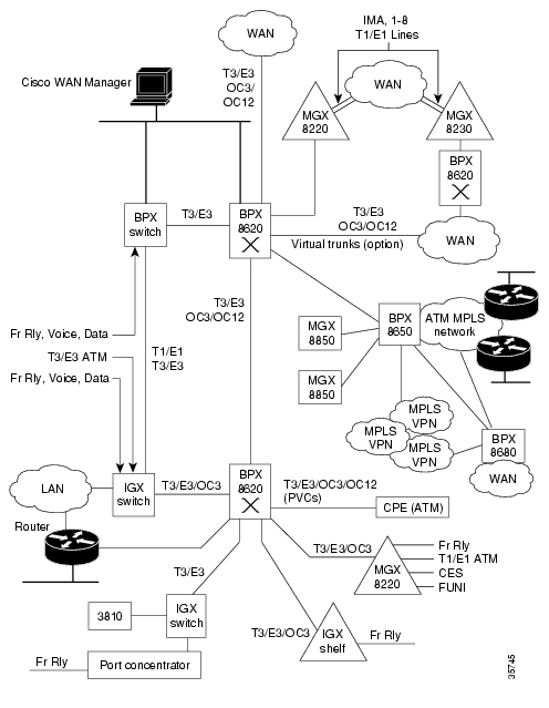
The Cisco BPX° 8600 series wide-area switches are standards-based high-capacity broadband ATM switches that provide backbone ATM switching, IP+ATM services including Multiprotocol Label Switching (MPLS) with trunk and CPU hot standby redundancy. The BPX 8600 series deliver a wide range of other user services (see Figure 1-1).
The BPX 8600 Series includes:
•
•
•
•
BPX 8620
The Cisco BPX 8620 switch is a scalable, standards-compliant unit, fully compatible with:
•
•
•
•
The BPX multishelf architecture integrates both IP and ATM services; therefore, enabling you to deploy widest range of value-added services in the industry. This architecture offer low-cost entry points for small sites up to unprecedented port density and scalability for the very largest sites. Finally, it supports both broadband services and narrowband services within a single platform.
The architecture supports both the broadband BPX switch and up to 16 edge concentrator shelves. The scalability results in full utilization of broadband trunks, and allows the BPX switch to be expanded incrementally to handle an almost unlimited number of subscribers.
The edge concentrators terminate traffic from a variety of interfaces, such as IP, Frame Relay, ATM, and circuit emulation, and adapt non-ATM traffic into ATM cells. This traffic is aggregated and sent to the BPX switch where it is switched on high-speed ATM links. This aggregation on a single platform maximizes the density of broadband and narrowband ports. High-density aggregation of low-speed services also optimizes the efficiency of the high-speed switching matrix and broadband card slots.
The multishelf view is a "logical" view. Physically, the edge concentrator shelves can be colocated with the BPX switch or they may be located remotely. The connection between a shelf and the BPX switch is a high-speed, optionally redundant ATM link.
The BPX switch consists of the BPX shelf with fifteen card slots that can be colocated with the
MGX 8200 or MGX 8800 and Service Expansion Shelf (SES) as required.Three of the slots on the BPX switch shelf are reserved for common equipment cards. The other twelve are general purpose slots used for network interface cards or service interface cards. The cards are provided in sets, consisting of a front card and its associated back card.
The BPX shelf can be mounted in a rack enclosure that provides mounting for a colocated SES and the MGX 8200 or MGX 8800 interface shelves.
Figure 1-1 BPX Switch General Configuration Example
BPX 8650
The BPX° 8650 is an IP+ATM switch that provides ATM-based broadband services and integrates Cisco IOS° software through Cisco 7200 series routers to deliver Multiprotocol Label Switching (MPLS) services.
The following are the core Internet requirements for the BPX 8650:
•
•
•
•
The following are supported by the BPX 8650:
•
•
•
•
•
•
•
•
BPX 8680
The BPX 8680 universal service switch is a scalable IP+ATM WAN edge switch that combines the benefits of Cisco IOS° IP with the extensive queuing, buffering, scalability, and quality-of-service (QoS) capabilities provided by the BPX 8600 and MGX 8800 series platforms.
The BPX 8680 switch incorporates a modular, multishelf architecture that scales from small sites to very large sites and enables service providers to meet the rapidly growing demand for IP applications while cost-effectively delivering today's services.
The BPX 8680 consists of one or more MGX 8200 series connected as feeders to a BPX 8620. Designed for very large installations, the BPX 8680 can scale to 16,000 DS1s by adding up to 16 MGX 8200 series concentrator shelves while still being managed as a single node.
BPX 8680-IP
The BPX 8680-IP scalable Layer 2/Layer 3 WAN solution integrating the proven multiservice switching technology of the Cisco BPX 8650 switch with the flexibility and scalability of the Cisco MGX 8200 series. The MGX 8200 series switch serves as an edge concentrator to the BPX 8650, which employs the BPX 8600 series switch modular, multishelf architecture to enable scalability. The BPX 8650 switch includes a Cisco 7204 label switch controller (LSC) and supports multiprotocol label switching (MPLS) for New World integrated infrastructures.
New with Release 9.3.30
With Release 9.3.30, the BPX switch software supports a number of new features:
•
•
•
•
•
•
•
•
•
•
Discontinued
The following are the older hardware components and technologies that are supported for five years from the time they are discontinued:
•
•
•
•
•
•
However, PNNI is available on the BPX through the Service Expansion Shelf (SES) PNNI. For a brief description, see Chapter 2, "BPX Switch Physical Overview," Service Expansion Shelf PNNI section.•
•
•
•
•
BPX Switch Operation
With the BCC-4 card, the BPX switch employs a nonblocking crosspoint switch matrix for cell switching that can operate at up to 19.2 Gbps peak. The switch matrix can establish up to 20 million point-to-point connections per second between ports.
The BXM cards support egress at up to 1600 Mbps and ingress at up to 800 Mbps. The enhanced egress rate enhances operations, such as multicast.
Access to and from the crosspoint switch matrix on the BCC is through multiport network and user access cards. It is designed to easily meet current requirements with scalability to higher capacity for future growth.
A BPX switch shelf is a self-contained chassis that may be rack-mounted in a standard 19-inch rack or open enclosure.
All control functions, switching matrix, backplane connections, and power supplies are redundant, and nondisruptive diagnostics continuously monitor system operation to detect any system or transmission failure. Hot-standby hardware and alternate routing capability combine to provide maximum system availability.
The BPX Switch with MGX 8220, MGX 8230, and MGX 8250 Shelves
Many network locations have increasing bandwidth requirements due to emerging applications and the confluence of voice, data, and video digital communications. To meet these requirements, you can overlay your existing narrowband networks with a backbone of BPX switches to utilize the high-speed connectivity of the BPX switch operating at up to 19.2 Gbps with its T3/E3/OC-3/OC-12 network and service interfaces.
The BPX switch service interfaces include BXM ports on the BPX switch and service ports on
MGX 8220, MGX 8230, and MGX 8250 shelves.The MGX 8220 shelves may be colocated in the same cabinet as the BPX switch, providing economical port concentration for T1/E1 Frame Relay, T1/E1 ATM, CES, and FUNI connections. Ten service module slots are supported for the MGX 8220.
As a BPX feeder, the MGX 8230 concentrates user ATM, Frame Relay (T1/E1 and T3/E3), T1/E1 ATM, and T1/E1 CES interfaces. Eight service module slots are supported for the MGX 8230.
The MGX 8250 can act as a stand-alone edge concentrator or as a feeder node for the BPX switch. Twenty-four service module slots are supported for the MGX 8250. The following interfaces are supported for user traffic:
•
•
•
•
Both the MGX 8230 and MGX 8250 support FRSM-VHS, Voice Service Module (VISM), and Route Processor Module (RPM) cards. For information about VISM, refer to the Cisco Voice Interworking Service Module Installation and Configuration Guide. For information about RPM, refer to the Cisco Route Processor Module Installation and Configuration Guide.
Multiprotocol Label Switching
The BPX 8650 MPLS switch combines a BPX switch with a separate MPLS controller (Cisco Series 7200 or 6400 router). By integrating the switching and routing functions, MPLS combines the reachability, scalability, and flexibility provided by the router function with the traffic engineering optimizing capabilities of the switch.
Multiprotocol Label Switching (MPLS) is a high-performance method for forwarding packets (frames) through a network. It enables routers at the edge of a network to apply simple labels to packets (frames). ATM switches or existing routers in the network core can switch packets according to the labels with minimal lookup overhead.
MPLS integrates the performance and traffic management capabilities of Data Link Layer 2 with the scalability and flexibility of Network Layer 3 routing. It is applicable to networks using any Layer 2 switching, but has particular advantages when applied to ATM networks. It integrates IP routing with ATM switching to offer scalable IP-over-ATM networks.
In contrast to label switching, conventional Layer 3 IP routing is based on the exchange of network reachability information. As a packet traverses the network, each router extracts all the information relevant to forwarding from the Layer 3 header. This information is then used as an index for a routing table lookup to determine the packet's next hop. This is repeated at each router across a network. At each hop in the network, the optimal forwarding of a packet must be again determined.
The information in IP packets, such as IP Precedence information and information on Virtual Private Network membership, is usually not considered when forwarding packets. Thus, to get maximum forwarding performance, typically only the destination address is considered. However, because other fields can be relevant, a complex header analysis must be done at each router that the packet meets.
The main concept of MPLS is to include a label on each packet.
Packets or cells are assigned short, fixed length labels. Switching entities perform table lookups based on these simple labels to determine where data should be forwarded.
The label summarizes essential information about routing the packet:
•
•
•
•
•
With Label Switching the complete analysis of the Layer 3 header is performed only once: at the edge label switch router (LSR) which is located at each edge of the network. At this location, the Layer 3 header is mapped into a fixed length label, called a label.
At each router across the network, only the label need be examined in the incoming cell or packet in order to send the cell or packet on its way across the network. At the other end of the network, an edge LSR swaps the label out for the appropriate header data linked to that label.
A key result of this arrangement is that forwarding decisions based on some or all of these different sources of information can be achieved by means of a single table lookup from a fixed-length label. For this reason, label switching makes it feasible for routers and switches to make forwarding decisions based upon multiple destination addresses.
Label switching integrates switching and routing functions, combining the reachability information provided by the router function, plus the traffic engineering benefits achieved by the optimizing capabilities of switches.
For multiservice networks, the BPX 8650 switch provides ATM, Frame Relay, and IP Internet service all on a single platform in a highly scalable way. Support of all these services on a common platform provides operational cost savings and simplifies provisioning for multiservice providers.
Cisco's MPLS solution is described in detail in the Cisco MPLS Controller Software Configuration Guide.
Private Network to Network Interface
Private Network to Network Interface (PNNI) is a link-state routing protocol that provides standards-based dynamic ATM routing with QoS support as defined by the ATM Forum. PNNI supports aggregation for private ATM addresses and links between switches, and can scale the network and its performance by configuring PNNI peer groups and hierarchical levels.
A key feature of the PNNI hierarchy mechanism is its ability to automatically configure itself in networks in which the address structure reflects the topology. It is responsive to changes in network resources and availability.
PNNI is available on the BPX switch when an optional Cisco Service Expansion Shelf (SES) PNNI is installed. This controller is connected locally to a BPX 8600 series switch to provide PNNI signaling and routing for the establishment of ATM and Frame Relay switched virtual circuits (SVCs) and Soft Permanent Virtual Circuits (SPVCs) over a BPX 8600 wide area network. The network created with BPX SES PNNI nodes also supports traditional ATM and Frame Relay permanent virtual circuits (PVCs) in a separately partitioned Automatic Routing Management network.
ATM SVCs are ATM connections that are established and maintained by a standardized signaling mechanism between ATM CPE (ATM end systems) across a Cisco WAN switching network. ATM SVCs are set up in accordance with user demand and removed when calls are completed, thus freeing up network resources.
BPX SES PNNI node resources, such as port virtual path identifier (VPI) range and bandwidth and trunk bandwidth, are partitioned between SVCs/SVPCs and PVCs. Resource partitioning provides a firewall between PVCs and SVCs/SVPs so that problems with CPE or large bursts do not affect the robustness and availability of PVC services. Bursty data for either PVCs or SVCs/SPVCs can always use any unused link bandwidth, regardless of partitioning.
For a brief description of the SES PNNI, see the Service Expansion Shelf PNNI section. Refer to the Cisco SES PNNI Controller Software Configuration Guide for detailed information abut the SES.
For further information about PNNI and the SES, refer to the Cisco SES PNNI Controller Software Configuration Guide.
Virtual Private Networks
This section is a brief description of the BPX switch's support for Virtual Private Networks (VPN). For additional information, refer to the Cisco MPLS Controller Software Configuration Guide.
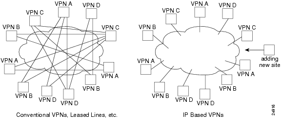
Conventional VPNs that use dedicated lease lines or Frame Relay Private Virtual Circuits (PVC) and a meshed network (see Figure 1-2) provide many advantages, but typically have been limited in efficiency and flexibility.
Instead of using dedicated leased lines or Frame Relay PVCs, and so on, for a VPN, an IP virtual private network uses the open connection less architecture of the Internet for transporting data as shown in Figure 1-2.
An IP virtual private network offers these benefits:
•
–
–
–
•
–
–
Figure 1-2 IP VPN Service Example
MPLS Virtual Private Networks
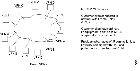
MPLS virtual private networks combine the advantages of IP flexibility and connection less operation with the QoS and performance features of ATM as shown in Figure 1-3.
The MPLS VPNs provide the same benefits as a plain IP Virtual Network plus:
•
–
–
–
–
•
•
Configure one site on one edge router or switch and network automatically does the rest.•
Each packet has a label identifying the destination VPN and customer site, providing the same level of privacy as Frame Relay.•
A single structure can support multiple services, such as voice VPNs, extranets, intranets, Internet, multiple VPNs.Figure 1-3 MPLS VPNs Example
Frame Relay to ATM Interworking
Interworking lets you retain your existing services and migrate to the higher bandwidth capabilities provided by BPX switch networks, as your needs expand. Frame Relay to ATM Interworking enables Frame Relay traffic to be connected across high-speed ATM trunks using ATM-standard Network and Service Interworking.
Two types of Frame Relay to ATM interworking are supported:
•
–
–
•
–
–
Network Interworking
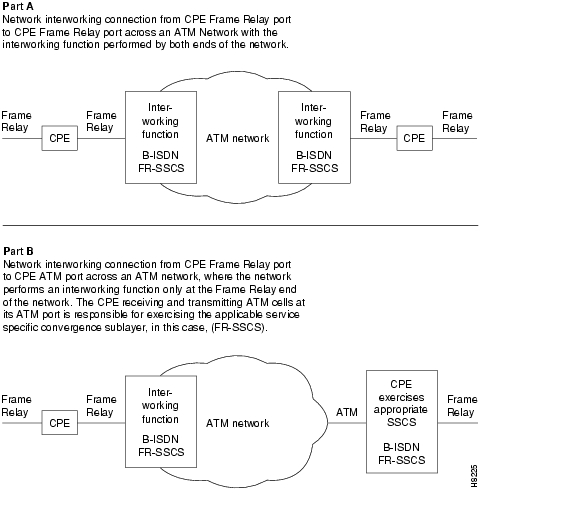
Part A of Figure 1-4 shows typical Frame Relay to network interworking. In this example, a Frame Relay connection is transported across an ATM network, and the interworking function is performed by both ends of the ATM network.
These are typical configurations:
•
•
•
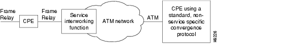
Part B of Figure 1-4 shows a form of network interworking where the interworking function is performed by only one end of the ATM network, and the CPE connected to the other end of the network must itself perform the appropriate service-specific convergence sublayer function.
These are sample configurations:
•
•
Network Interworking is supported by the FRM, UFM-C, and UFM-U on the IGX switch, and the FRSM on the MGX 8200 series. The Frame Relay Service Specific Convergence Sublayer (FR-SSCS) of AAL5 is used to provide protocol conversion and mapping.
Figure 1-4 Frame Relay to ATM Network Interworking
Service Interworking
Figure 1-5 shows a typical example of Service Interworking. Service Interworking is supported by the FRSM on the MGX 8220 and the UFM-C and UFM-U on the IGX switch. Translation between the Frame Relay and ATM protocols is performed in accordance with RFC 1490 and RFC 1483.
Unlike Network Interworking, in a Service Interworking connection between an ATM port and a Frame Relay port, the ATM device does not need to be aware that it is connected to an interworking function.
The Frame Relay service user does not implement any ATM specific procedures. Also, the ATM service user does not need to provide any Frame Relay specific functions. All translational (mapping functions) are performed by the intermediate interworking function.
This is a typical configuration for service interworking:
•
•
Note
Figure 1-5 Frame Relay to ATM Service Interworking
Tiered Networks
Networks may be configured as:
•
All nodes perform routing and communicate fully with one another, or•
Interface shelves are connected to routing hubs, where the interface shelves are configured as nonrouting nodes.By allowing CPE connections to connect to a nonrouting node (interface shelf), a tiered network is able to grow in size beyond that which would be possible with only routing nodes comprising the network.
Starting with Release 8.5, tiered networks support both BPX switch routing hubs and IGX switch routing hubs. Voice and data connections originating and terminating on IGX switch interface shelves (feeders) are routed across the routing network through the associated IGX switch routing hubs.
Tiered networks support multiservice connections, including Frame Relay, circuit data, voice, and ATM. By allowing the customer's equipment to connect to a nonrouting node (interface shelf), a tiered network is able to grow in size beyond that which would be possible with only routing nodes.
Intermediate routing nodes must be IGX switches. IGX switch interface shelves are the only interface shelves that can be connected to an IGX switch routing hub. With this addition, a tiered network provides a multiservice capability (Frame Relay, circuit data, voice, and ATM).
Routing Hubs and Interface Shelves
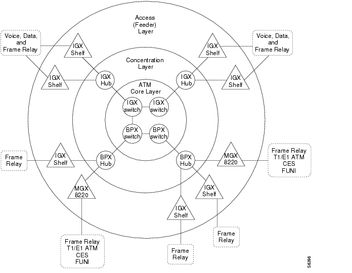
In a tiered network, interface shelves at the access layer (edge) of the network are connected to routing nodes by means of the feeder trunks as shown in Figure 1-6.
•
Those routing nodes with attached interface shelves are referred to as routing hubs.•
The interface shelves, sometimes referred to as feeders, are nonrouting nodes.The routing hubs route the interface shelf connections across the core layer of the network.The interface shelves do not need to maintain network topology nor connection routing information. This task is left to their routing hubs.
This architecture provides an expanded network consisting of a number of nonrouting nodes
(interface shelves) at the edge of the network that are connected to the network by their routing hubs.BPX Switch Routing Hubs
T1/E1 Frame Relay connections originating at IGX switch interface shelves and T1/E1 Frame Relay, T1/E1 ATM, CES, and FUNI connections originating at MGX 8220 interface shelves are routed across the routing network through the associated BPX switch routing hubs.
The following requirements apply to BPX switch routing hubs and their associated interface shelves:
•
•
•
•
•
•
•
•
•
•
Figure 1-6 Tiered Network with BPX Switch and IGX Switch Routing Hubs
BPX Routing Hubs in a Tiered Network
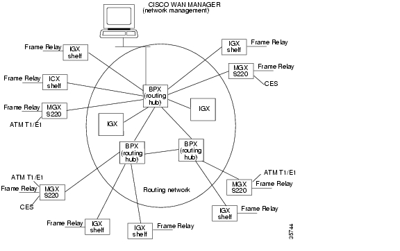
Tiered networks with BPX routing hubs have the capability of adding interface shelves/feeders (nonrouting nodes) to an IGX/BPX routing network as shown in Figure 1-7. Interface shelves allow the network to support additional connections without adding additional routing nodes.
The MGX 8220 or MGX 8800 and IGX 8400 nodes configured as interface shelves are connected to BPX routing hubs.
The MGX 8220 and MGX 8800 support frame T1/E1, X.21 and HSSI Frame Relay, ATM T1/E1, and CES.
Figure 1-7 Tiered Network with BPX Routing Hubs
Tiered Network Implementation
The following requirements apply to BPX routing hubs and their associated interface shelves:
•
•
•
•
•
•
•
•
•
The definitions for the tier network are listed in Table 1-1.
Upgrades
Converting an IGX node to an interface shelf requires reconfiguring connections on the node because no upgrade path is provided in changing a routing node to an interface shelf.
A BPX node, acting as a Hub Node, is not restricted from providing any other feature normally available on BPX nodes. A BPX Hub supports up to 16 interface shelves.
Connections within tiered networks consist of distinct segments within each tier. A routing segment traverses the routing network, and an interface shelf segment provides connectivity to the interface shelf end-point. Each of these segments are added, configured and deleted independently of the other segments.
Use the Cisco WAN Manager Connection Manager to configure and control these individual segments as a single end-to-end connection.
Interface shelves are attached to the routing network through a BPX routing hub using a BXM trunk (T3/E3 or OC-3) or BNI trunk (T3/E3). The connection segments within the routing network are terminated on the BNI feeder trunks.
All Frame Relay connection types that can terminate on the BPX are supported on the BNI feeder trunk (VBR, CBR, ABR, and ATF types). No check is made by the routing network to validate whether the connection segment type being added to a BNI feeder trunk is actually supported by the attached interface shelf.
Colocating Routing Hubs and Interface Shelves
The trunk between an interface shelf and the routing network is a single point of failure; therefore, the interface shelves can be colocated with their associated hub node. Card level redundancy is supported by the Y-Cable redundancy for the BXM, BNI, and UXM.
Network Management
Communication between CPE devices and the routing network is provided in accordance with Annex G of Recommendation Q.2931. This is a bidirectional protocol for monitoring the status of connections across a UNI interface. (Note: the feeder trunk uses the STI cell format to provide the ForeSight rate controlled congestion management feature.)
Communication includes the real-time notification of the addition or deletion of a connection segment and the ability to pass the availability (active state) or unavailability (inactive state) of the connections crossing this interface.
A proprietary extension to the Annex G protocol is implemented that supports the exchange of node information between an interface shelf and the routing network. This information is used to support the IP Relay feature and the Robust Update feature used by network management.
Network Management access to the interface shelves is through the IP Relay mechanism using SNMP or TFTP or by direct attachment to the interface shelf. The IP Relay mechanism relays traffic from the routing network to the attached interface shelves. No IP Relay support is provided from the interface shelves into the routing network.
The BPX routing hub is the source of the network clock for its associated feeder nodes. Feeders synchronize their time and date to match their routing hub.
Robust Object and Alarm Updates are sent to a network manager that has subscribed to the Robust Updates feature. Object Updates are generated whenever an interface shelf is added or removed from the hub node and when the interface shelf name or IP Address is modified on the interface shelf. Alarm Updates are generated whenever the alarm state of the interface shelf changes between Unreachable, Major, Minor, and OK alarm states.
An interface shelf is displayed as a unique icon in the Cisco WAN Manager topology displays. The colors of the icon and connecting trunks indicate the alarm state of each.
Channel statistics are supported by FRM, ASI, UXM, and MGX 8220 endpoints. The Broadband Network Interface (BNI) card does not support channel statistics. Trunk Statistics are supported for the feeder trunk and are identical to the existing BNI trunk statistics.
Inverse Multiplexing ATM
Where greater bandwidths are not needed, the Inverse Multiplexing ATM (IMA) feature provides a low-cost trunk between two BPX switches.
The IMA feature allows BPX switches to be connected to one another over any of the eight T1 or E1 trunks provided by an IMATM module on an MGX 8220 shelf. A BNI or BXM port on each BPX switch is directly connected to an IMATM module in an MGX 8220 by a T3 or E3 trunk. The IMATM modules are then linked together by any of the eight T1 or E1 trunks. IMA is also configurable on lines.
Refer to the Cisco MGX 8220 Reference and the Cisco WAN Switching Command Reference publications for further information.
Virtual Trunking
Virtual trunking provides the ability to define multiple trunks within a single physical trunk port interface. Virtual trunking benefits include the following:
•
•
•
•
•
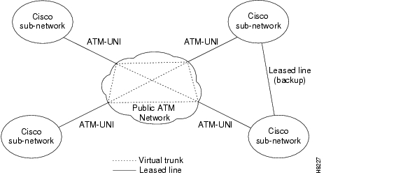
A virtual trunk may be defined as a "trunk over a public ATM service." The trunk really doesn't exist as a physical line in the network. Rather, an additional level of reference, called a virtual trunk number, is used to differentiate the virtual trunks found within a physical trunk port.
Figure 1-8 shows four Cisco WAN switching networks, each connected to a Public ATM Network through a physical line. The Public ATM Network is shown linking all four of these subnetworks to every other one with a full meshed network of virtual trunks. In this example, each physical line is configured with three virtual trunks.
Figure 1-8 Virtual Trunking Example
Traffic and Congestion Management
The BPX switch provides ATM standard traffic and congestion management per ATM Forum TM 4.0 using BXM cards.
The Traffic Control functions include:
•
•
•
•
•
•
In addition to these standard functions, the BPX switch provides advanced traffic and congestion management features including:
•
•
–
–
•
•
•
•
•
•
•
Advanced CoS Management
Advanced Class of Service (CoS) management provides per-VC queueing and per-VC scheduling. CoS management provides fairness between connections and firewalls between connections. Firewalls prevent a single noncompliant connection from affecting the QoS of compliant connections. The noncompliant connection simply overflows its own buffer.
The cells received by a port are not automatically transmitted by that port out to the network trunks at the port access rate. Each VC is assigned its own ingress queue that buffers the connection at the entry to the network. With ABR with VS/VD or with Optimized Bandwidth Management (ForeSight), the service rate can be adjusted up and down depending on network congestion.
Network queues buffer the data at the trunk interfaces throughout the network according to the connection's Class of Service. Service classes are defined by standards-based QoS. Classes can consist of the five service classes defined in the ATM standards as well as multiple sub-classes to each of these classes. Classes can range from constant bit rate services with minimal cell delay variation to variable bit rates with less stringent cell delay.
When cells are received from the network for transmission out a port, egress queues at that port provide additional buffering based on the Service Class of the connection.
CoS management provides an effective means of managing the Quality of Service defined for various types of traffic. It permits network operators to segregate traffic to provide more control over the way that network capacity is divided among users. This is especially important when there are multiple user services on one network. The BPX switch provides separate queues for each traffic class.
Rather than limiting the user to the five broad classes of service defined by the ATM standards committees, CoS management can provide up to 16 classes of service (service subclasses) that you can further define and assign to connections. Some of the COS parameters that may be assigned include:
•
•
•
•
These class of service parameters are based on the standards-based Quality of Service parameters and are software programmable by the user.
Automatic Routing Management
With Automatic Routing Management, connections in Cisco WAN switching networks are added if there is sufficient bandwidth across the network and are automatically routed when they are added.
You need enter only the endpoints of the connection at one end of the connection and the IGX switch and BPX switch software automatically set up a route based on a sophisticated routing algorithm. This feature is called Automatic Routing Management. It is a standard feature on the IGX and BPX switches.
System software automatically sets up the most direct route after considering the network topology and status, the amount of spare bandwidth on each trunk, as well as any routing restrictions entered by the user (for example, avoid satellite links). This avoids having to manually enter a routing table at each node in the network. Automatic Routing Management simplifies adding connections, speeds rerouting around network failures, and provides higher connection reliability.
Cost-Based Routing Management
You can selectively enable cost-based route selection as the route selection per node. With cost-based routing management, a trunk cost is assigned to each trunk (physical and virtual) in the network. The routing algorithm then chooses the lowest-cost route to the destination node. The lowest cost routes are stored in a cache to reduce the computation time for on-demand routing.
Cost-based routing can be enabled or disabled at anytime. There can be a mixture of cost-based and hop-based nodes in a network.
For more detailed information about cost-based Automatic Routing Management, see the Cost-Based Connection Routing section.
Priority Bumping
Priority Bumping (PB) allows BPX and IGX switch connections classified as more important (through the CoS value) to "bump" (that is, set aside) existing connections of lesser importance. While the Automatic Routing Management feature is capable of automatically redirecting all failed connections onto other paths, priority bumping lets you prioritize and sustain more important connections when network resources are diminished to a point that all connections cannot be sustained. Network resources are reclaimed for the more important connections by bumping (derouting) the traffic on less important connections.
Priority bumping is triggered by insufficient resources (such as bandwidth), resulting from any number events, including changes to the network made by using the commands addcon, upcon, cnfcon, cnnfcos, cnfpref, cnftrk, and deltrk. Other triggers include trunk line/card failure, node failure, and communication failure. The most prominent event is a trunk failure.
For information on setting up Priority Bumping, refer to the Cisco WAN Switching Command Reference, Release 9.3.30.
Concurrent Routing
CR is an enhancement to the Automatic Routing Management feature and does not alter the Automatic Routing Management messaging protocol. The Automatic Routing Management functionality is operational whether or not CR is enabled on a node. If CR is disabled, the node exhibits preswitch software Release 9.3.30 behavior, which includes collisions and back off. When CR is enabled, collisions occur less frequently.
Concurrent Routing (CR) allows multiple routing requests to be processed simultaneously on a node. For example, a node can initiate (master node) one or more routes while simultaneously accepting other routes that pass through it (via node) or terminate at it (slave node).
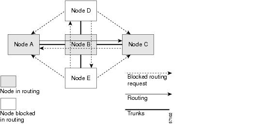
If CR is not enabled on a node, routing requests received while a connection is in the process of being routed, is routed sequentially. As a result, only one bundle at a time can be routed on a node. This sequential routing algorithm under utilizes the computational power of the switch. Sequential routing is illustrated in Figure 1-9.
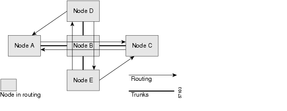
CR allows the processor of the switch to be more effectively utilized by allowing multiple routes to be in progress concurrently. The result is better overall reroute performance. Performance improvement is not realized for individual or topologically disjoint reroutes. The key performance metric that is improved by CR is network settling time. Network settling time is defined by the longest settling time for any single node, assuming all of the nodes start routing at the same time. The number of nodes and connections in the network, network topology, and other configureable routing parameters all affect network settling time. CR is illustrated in Figure 1-10.
Figure 1-9 Sequential Routing
Figure 1-10 Concurrent Routing
The CR Feature provides the following benefits:
•
•
•
•
•
•
•
•
Note
Before CR can be enabled on any node in the network, all of the nodes in a network must be upgraded to switch software Release 9.3.30. The cnfcmparm command sets the route concurrency level to an integer value greater than 1 but not greater than 8. Once CR has been enabled, it operates automatically. However, it is not necessary for CR to be enabled on every node in a network for CR to function on those nodes that are CR enabled. CR can be turned off by specifying a concurrency level of 1. For a detailed discussion of the cnfcmparm command and other commands pertinent to the CR feature, refer to the Cisco WAN Switching Command Reference, Release 9.3.30.
A maximum of eight concurrent routes can be configured on a node. However, a node is able only to master two routes concurrently, any remaining concurrent routing capacity is used for routes or as a slave. Allowing more than eight concurrent routes would have diminishing returns, because processor utilization would become excessive. A node continues to master new route requests (provided route candidates exist), or serve as a via node or slave node for new routes, until it reaches the route concurrency level that is configured on the node.
CR has the potential to dramatically reduce CPU idle time. To preserve enough CPU time for other switch features or for users to interact effectively with a node, a mechanism is implemented to limit (throttle) route concurrency. When CPU utilization exceeds a defined threshold (throttle level), new route activity is temporarily suspended to preserve node responsiveness. Throttling continues until CPU utilization drops below a second threshold (resume level), which is less than or equal to the throttle level. Allowing the resume level to be less than the throttle level provides a hysteresis mechanism to avoid oscillation around the throttling point. The default CPU throttling values for master, via and slave routes are set at 80 percent of CPU capacity for throttling and 60 percent of CPU capacity to resume new route activity. Separate throttle and resume points can be set for master, via, and slave routes to allow tailoring of route behavior. However, if you need to change the settings, contact TAC for configuring the levels.
If a node masters two or more routes that share the same via node or slave node, the routes have overlapping paths. Due to messaging protocol limitations, a node is able only to master concurrent routes that do not have overlapping paths. The Path Blocking algorithm checks each master route candidate that a node might initiate to see if it overlaps with another route in progress that is mastered by the node. If there is any overlap, the candidate is rejected and candidate selection continues. The degree to which Path Blocking limits concurrent master routes on a node is a function of network topology and connection provisioning. Path blocking does not affect nodes that are serving only as a via node or a slave node.
PB is a computation-intensive process, which allows switch connections classified as more important (based on CoS value) to "bump" connections of lesser importance. CR may be restricted if the PB feature is enabled on a network. Both PB and CR are processor intensive. To avoid excessive processor utilization, no new route requests are initiated or accepted on a node that participates in a PB route, until that PB route is complete.
ABR Standard with VS/VD Congestion Control
This section describes Standard ABR with VS/VD. The BPX/IGX switch networks provide a choice of two dynamic rate based congestion control methods, ABR with VS/VD and Optimized Bandwidth Management (ForeSight).
When an ATM connection is configured between BXM cards for Standard ABR with VS/VD per ATM Forum TM 4.0, Resource Management (RM) cells are used to carry congestion control feedback information back to the connection source from the connection destination.
The ABR sources periodically interleave RM cells into the data they are transmitting. These RM cells are called forward RM cells because they travel in the same direction as the data. At the destination these cells are turned around and sent back to the source as backward RM cells.
The RM cells contain fields to increase or decrease the rate (the CI and NI fields) or set it at a particular value (the explicit rate ER field). The intervening switches may adjust these fields according to network conditions. When the source receives an RM cell, it must adjust its rate in response to the setting of these fields.
When spare capacity exists with the network, ABR with VS/VD permits the extra bandwidth to be allocated to active virtual circuits.
Optimized Bandwidth Management (ForeSight) Congestion Control
This section describes Optimized Bandwidth Management (ForeSight). The BPX/IGX switch networks provide a choice of two dynamic rate-based congestion control methods, ABR with VS/VD and Cisco Optimized Bandwidth Management (ForeSight).
Optimized Bandwidth Management (ForeSight) can be used for congestion control across BPX/IGX switches for connections that have one or both endpoints terminating on cards other than BXM. The ForeSight feature is a dynamic closed-loop, rate-based congestion management feature that yields bandwidth savings compared to non-ForeSight equipped trunks when transmitting bursty data across cell-based networks.
When there is unused network bandwidth available, ForeSight permits users to burst above their committed information rate for extended periods of time. This enables users to maximize the use of network bandwidth while offering superior congestion avoidance by actively monitoring the state of shared trunks carrying Frame Relay traffic within the network.
ForeSight monitors each path in the forward direction to detect any point where congestion may occur and returns the information back to the entry to the network. When spare capacity exists with the network, ForeSight permits the extra bandwidth to be allocated to active virtual circuits. Each PVC is treated fairly by allocating the extra bandwidth based on each PVC's committed bandwidth parameter.
If the network reaches full utilization, ForeSight detects this and quickly acts to reduce the extra bandwidth allocated to the active PVCs. ForeSight reacts quickly to network loading to prevent dropped packets. Periodically, each node automatically measures the delay experienced along a Frame Relay PVC. This delay factor is used in calculating the ForeSight algorithm.
With basic Frame Relay service, only a single rate parameter can be specified for each PVC. With ForeSight, the virtual circuit rate can be specified based on a minimum, maximum, and initial transmission rate for more flexibility in defining the Frame Relay circuits.
ForeSight provides effective congestion management for traversing broadband ATM for the PVC. ForeSight operates at the cell-relay level that lies below the Frame Relay services provided by the IGX switch. With the queue sizes utilized in the BPX switch, the bandwidth savings is approximately the same as experienced with lower speed trunks. When the cost of these lines is considered, the savings offered by ForeSight can be significant.
Network Management
BPX switches provide one high-speed and two low-speed data interfaces for data collection and network management:
•
•
Each BPX switch can be configured to use optional low-speed modems for inward access by the Cisco Technical Response Team for network troubleshooting assistance or to autodial Cisco Customer Service to report alarms remotely. If desired, another option is remote monitoring or control of customer premise equipment through a window on the Cisco WAN Manager workstation.
A Cisco WAN Manager NMS workstation connects through the Ethernet to the LAN port on the BPX and provides network management through SNMP. Statistics are collected by Cisco WAN Manager using the TFTP protocol.
You can also use the Cisco WAN Manager's Connection Manager to manage:
•
•
•
The following are the Network Management software applications:
•
•
For further information on network management, refer to the Cisco WAN Manager User's Guide.
Cisco WAN Manager
Cisco WAN Manager, a standards-based multiprotocol management architecture, is a single unified management platform that utilizes HP OpenView° to manage BPX, IGX, and SES devices. Regardless of the size or configuration of your network, Cisco WAN Manager collects extensive service statistics, tracks resource performance, and provides powerful remote diagnostic and control functions for WAN maintenance.
Online help screens, graphical displays, and easy command line mnemonics make Cisco WAN Manager user-friendly. Plentiful hard disk storage is provided to allow accumulating time of day statistics on many network parameters simultaneously. The data is accumulated by the node's controller card and transmitted to the Cisco WAN Manager workstation where it is stored, processed, and displayed on a large color monitor.
Cisco WAN Manager connects to the network over an Ethernet LAN connection. With Ethernet, you can establish Cisco WAN Manager connectivity to remote nodes through Frame Relay over TCP/IP to the LAN connector on the local node, or through inband ILMI.
Cisco WAN Manager provides inband management of network elements through SNMP agent interfaces and MIBs embedded in each node and interface shelf. The SNMP agent allows a user to manage a StrataCom network or subnetwork from any SNMP-based integrated network management system (INMS).
The following are the functions of Cisco WAN Manager:
•
•
•
•
•
•
•
Network Interfaces
Network interfaces connect the BPX switch to other BPX or IGX switches to form a wide-area network. The following are the trunk interfaces for the BPX switch:
•
•
•
•
The T3 physical interface utilizes DS3 C-bit parity and the 53-byte ATM physical layer cell relay transmission using the Physical Layer Convergence Protocol.
The E3 physical interface uses G.804 for cell delineation and HDB3 line coding.
The following are the physical interfaces for the BXM-622 cards:
•
•
•
–
The BPX switch supports network interfaces up to 622 Mbps and provides the architecture to support higher broadband network interfaces as the need arises.
Optional redundancy is on a one-to-one basis. The physical interface can operate either in a normal or looped clock mode. As an option, the node synchronization can be obtained from the DS3 extracted clock for any selected network trunk.
Service Interfaces
Service interfaces connect ATM customer equipment to the BPX switch. ATM User-to-Network Interfaces (UNI) and ATM Network-to-Network Interfaces (NNI) terminate on the ATM Service Interface (ASI) cards and on BXM T3/E3, OC-3, and OC-12 cards configured for the service interfaces (UNI access mode).
The BXM T3/E3 card supports the standard T3/E3 interfaces.
The BXM-155 cards support SMF, SMFLR, and MMF physical interfaces.
The BXM-622 cards support SMF, SMFLR, and SMFXLR physical interfaces.
Note
The BXM cards support cell relay connections that are compliant with both the physical layer and ATM layer standards.
The MGX 8220 interfaces to a BNI or BXM card on the BPX, through a T3, E3, or OC-3 interface. The MGX 8220 provides a concentrator for T1 or E1 Frame Relay and ATM connections to the BPX switch with the ability to apply Optimized Bandwidth Management (ForeSight) across a connection from end-to-end. The MGX 8220 also supports CES and FUNI (Frame-based UNI over ATM) connections.
Statistical Alarms and Network Statistics
The BPX Switch system manager can configure alarm thresholds for all statistical type error conditions. Thresholds are configureable for conditions such as frame errors, out of frame, bipolar errors, dropped cells, and cell header errors. When an alarm threshold is exceeded, the NMS screen displays an alarm message.
Graphical displays of collected statistics information, a feature of the Cisco WAN Manager NMS, are a useful tool for monitoring network usage. The following are the four general categories used for collecting statistics:
•
•
•
•
The statistics are collected in real-time throughout the network and forwarded to the Cisco WAN Manager workstation for logging and display. The link from the node to the Cisco WAN Manager workstation uses a protocol to acknowledge receipt of each statistics data packet.
For more details on statistics and statistical alarms, refer to the Cisco WAN Manager User's Guide.
Node Synchronization
A BPX service switch network provides network-wide, intelligent clock synchronization. It uses a fault-tolerant network synchronization architecture recommended for Integrated Services Digital Network (ISDN). The BPX switch internal clock operates as a Stratum 3 clock per ANSI T1.101.
Because the BPX switch is designed to be part of a larger communications network, it is capable of synchronizing to higher-level network clocks as well as providing synchronization to lower-level devices. You can configure any network access input to synchronize the node. Any external T1 or E1 input can also be configured to synchronize network timing.
A clock output allows synchronizing an adjacent IGX switch or other network device to the BPX switch and the network. In nodes equipped with optional redundancy, the standby hardware is locked to the active hardware to minimize system disruption during system switchovers.
The following are the sources used to configure the BPX Service Node to select the clock:
•
•
•
Switch Software Description
The Cisco WAN switching cell relay system software shares most core system software, as well as a library of applications, between platforms. System software provides basic management and control capabilities to each node.
BPX node system software manages its own configuration, fault-isolation, failure recovery, and other resources. Because no remote resources are involved, rapid response to local problems. This distributed network control, rather than centralized control, provides increased reliability.
Software among multiple nodes cooperates to perform network-wide functions such as trunk and connection management. The multiprocessor approach ensures rapid response with no single point of failure. System software applications provide advanced features that you can install and configure as required.
The following are the software features:
•
•
•
•
•
•
The system software, configuration database, and the firmware that controls the operation of each card type is resident in programmable memory and can be stored off-line in the Cisco WAN Manager NMS for immediate backup if necessary. This software and firmware is easily updated remotely from a central site or from Cisco Customer Service, which reduces the likelihood of early obsolescence.
Connections and Connection Routing
The routing software supports the establishment, removal and rerouting of end-to-end channel connections. The following are the three routing modes:
•
•
•
The system software uses the following criteria when it establishes an automatic route for a connection:
•
•
•
When a node reroutes a connection, it uses these criteria and also looks at the priority that has been assigned and any user-configured routing restrictions. The node analyzes trunk loading to determine the number of cells or packets the network can successfully deliver. Within these loading limits, the node can calculate the maximum combination allowed on a network trunk of each type of connection, for example, synchronous data, ATM traffic, Frame Relay data, multimedia data, voice, and compressed voice.
Network-wide T3, E3, OC-3, or OC-12 connections are supported between BPX switches terminating ATM user devices on the BPX switch UNI ports. The connections are routed using the virtual path or virtual circuit addressing fields in the ATM cell header.
Narrowband connections are routed over high-speed ATM backbone networks built on BPX broadband switches. FastPacket addresses are translated into ATM cell addresses that are then used to route the connections between BPX switches, and to ATM networks with mixed vendor ATM switches. Routing algorithms select broadband links only, which avoids narrowband nodes that could create a choke point.
Connection Routing Groups
The rerouting mechanism ensures that connections are presorted in order of cell loading when they are added. Each routing group contains connections with loading in a particular range. The group containing the connections with the largest cell loadings is rerouted first, and subsequent groups are then rerouted on down to the last group that contains connections with the smallest cell loadings.
The following are three configurable parameters to configure the rerouting groups:
•
•
•
You configure the three routing group parameters by using the cnfcmparm command.
For example, there might be 10 groups, with the starting load size of the first group at 50, and the incremental load size of each succeeding group being 10 cells. Then group 0 would contain all connections requiring 0 to 59 cell load units, group 1 would contain all connections requiring from 60 to 69 cell load units, on up through group 9 which would contain all connections requiring 140 or more cell load units.
An example of the routing group configuration is listed in Table 1-2.
Cost-Based Connection Routing
In standard Automatic Routing Management, the path with the fewest number of hops to the destination node is chosen as the best route. Cost-based route selection uses an administrative trunk cost routing metric. The path with the lowest total trunk cost is chosen as the best route.
Cost-based route selection is based on Dijkstra's Shortest Path Algorithm, which is widely used in network routing environments. You can use cost-based route selection, such as cost-based Automatic Routing Management to give preference to slower privately owned trunks over faster public trunks that charge based on usage time. While providing a more standard algorithm for route selection, network operators more have control over the usability of the network trunks.
Major Features of Cost-Based Automatic Routing Management
The following are major functional elements of Cost-Based Route Selection:
•
•
The cost can also be changed after connections have been routed over the trunk. Such a change does not initiate automatic connection rerouting, nor does it cause any outage to the routed connections. If the new trunk cost causes the allowable route cost for any connections to be exceeded, the connections must be manually rerouted to avoid the trunk. Large-scale simultaneous network-wide rerouting is avoided and gives you control over the connection reroute outage.
•
The cache contains lowest cost routes as they are selected. Subsequent routing cycles use these existing routes if the routing criteria are met. Otherwise, on-demand routing is initiated. This caching greatly benefits environments where routing criteria is very similar among connections.
Enabling cost-based route selection automatically enables cache usage. Enabling Hop-Based Route Selection automatically disables cache usage. Cache usage can also be independently enabled or disabled for both types of route selection.
•
•
Automatic Routing Management does not use the worst case end-to-end queueing delay in route selection for delay sensitive BPX connection types (ATM CBR). Cost-based route selection does not change this.
•
For routing based on trunk cost, the cost cap is the acceptable end-to-end cost. This cap is configured per connection. The default cost cap is 100, which is derived from the maximum hops per route (10) and default cost per trunk (10). You can change the cost cap at any time. If the cost cap is decreased below the current route cost, the connection is not automatically rerouted. A manual reroute is required to route the connection to fit under the new cost cap. This gives you more control over the connection reroute outage.
•
•
Cost-Based Automatic Routing Management Commands
You use these switch software Command Line Interface (CLI) commands for cost-based route selection as described in Table 1-3. For detailed information about the use of BPX switch commands, refer to the Cisco WAN Switching Command Reference.
Network Synchronization
Cisco WAN switching cell relay networks use a fault-tolerant network synchronization method of the type recommended for Integrated Services Digital Network (ISDN). You can select any circuit line, trunk, or an external clock input to provide a primary network clock. Any line can be configured as a secondary clock source in the event that the primary clock source fails.
All nodes are equipped with a redundant, high-stability internal oscillator that meets Stratum 3 (BPX) or Stratum 4 requirements. Each node keeps a map of the network's clocking hierarchy. The network clock source is automatically switched in the event of failure of a clock source.
There is less likelihood of a loss of data resulting from reframes that occur during a clock switchover or other momentary disruption of network clocking with cell-based networks than there is with traditional TDM networks. Data is held in buffers and packets are not sent until a trunk has regained frame synchronism to prevent loss of data.
Switch Availability
This section describes some of the features that contribute to network availability. Cisco WAN hardware and software components are designed to provide a switch availability in excess of 99.99 percent. Network availability is impacted by link failure, which has a higher probability of occurrence than equipment failure.
Cisco WAN network switches are designed so that connections are automatically rerouted around network trunk failures, often before users detect a problem. System faults are detected and corrective action taken often before they become service affecting.
Node Redundancy
System availability is a primary requirement with the BPX switch. The designed availability factor of a BPX switch is 99.99 percent based on a node equipped with optional redundancy and a network designed with alternate routing available. The system software, as well as firmware for each individual system module, incorporates various diagnostic and self-test routines to monitor the node for proper operation and availability of backup hardware.
For protection against hardware failure, a BPX switch shelf can be equipped with the following redundancy options:
•
•
•
•
•
•
If redundancy is provided for a BPX switch, when a hardware failure occurs, a hot-standby module is automatically switched into service, replacing the failed module. All cards are hot-pluggable, so replacing a failed card in a redundant system can be performed without disrupting service.
Since the power supplies share the power load, redundant supplies are not idle. All power supplies are active; if one fails, then the others pick up its load. The power supply subsystem is sized so that if any one supply fails, the node continues to be supplied with adequate power to maintain normal operation of the node. The node monitors each power supply voltage output and measures cabinet temperature to be displayed on the NMS terminal or other system terminal.
Node Alarms
Each BPX switch shelf within the network runs continuous background diagnostics to verify the proper operation of all active and standby cards, backplane control, data, and clock lines, cabinet temperature, and power supplies. Background tests are transparent to normal network operation.
Each card in the node has front-panel LEDs to indicate active, failed, or standby status.
Each power supply has green LEDs to indicate proper voltage input and output.
An Alarm, Status, and Monitor card collects all the node hardware status conditions and reports it using front panel LED indicators and alarm closures. Indicators are provided for major alarm, minor alarm, ACO, power supply status, and alarm history. Alarm relay contact closures for major and minor alarms are available from each node through a 15-pin D-type connector for forwarding to a site alarm system.
BPX switches are completely compatible with the network status and alarm display provided by the Cisco WAN Manager NMS workstation. In addition to providing network management capabilities, major and minor alarm status are displayed on the topology screen for all nodes in a network.
The Cisco WAN Manager NMS also provides a maintenance log capability with configurable filtering of the maintenance log output by node name, start time, end time, alarm type, and user-specified search string.
![]()
![]()
![]()
![]()
![]()
![]()
![]()
![]()
Posted: Tue May 10 21:06:46 PDT 2005
All contents are Copyright © 1992--2005 Cisco Systems, Inc. All rights reserved.
Important Notices and Privacy Statement.