|
|

Table Of Contents
Solution Overview
The Cisco Gigabit-Ethernet Optimized VoD Solution, Release 2.0 builds on the switch-in-Dhub (distribution hub) architecture established for previous releases, introducing support for additional switching and transport components.
The following are not included in Release 2.0:
•
Additional functionality for the no-switch-in-Dhub architecture described in Release 1.1
•
•
Note
http://www.cisco.com/univercd/cc/td/doc/solution/vodsols/index.htm
However, it is not necessary to read previous releases of the solution documentation before reading this document.This chapter presents the following major topics:
Solution Description
Generic Architecture
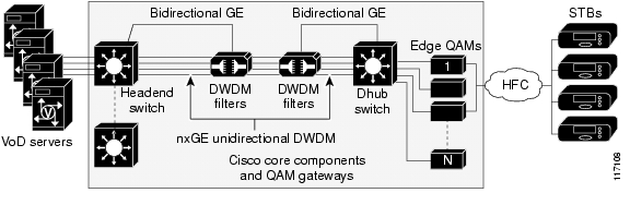
Figure 1-1 illustrates the generic switch-in-Dhub plus optical transport architecture used by Releases 1.1 and 2.0 of the solution. All solution components are located in either a video headend or a Dhub site. The basic solution topology is an Ethernet hub and spoke between the headend site and multiple Dhub sites. The switch in the headend is called the headend switch, and the switch in the Dhub is called the Dhub switch. Where the Cisco uMG9850 QAM Module is used, a Cisco Catalyst 4507 switch, adjacent to the Dhub switch, is also required. This switch is referred to as the QAM switch.
Note
Figure 1-1 High-Level Architecture of the Cisco Gigabit-Ethernet Optimized VoD Solution,
Release 2.0
Note
http://www.cisco.com/univercd/cc/td/doc/solution/vodsols/geopt1_1/voddig/index.htmThe essential feature of Cisco Gigabit-Ethernet Optimized VoD Solution, Release 2.0 (referred to herein simply as "Release 2.0" or the "solution"), is the use of unidirectional 10 GE in the downstream direction, combined with 1 or 10 GE in the upstream direction. Release 2.0 includes topologies in which unidirectional 10-GE links are routed directly between the headend and a target Dhub, as well as topologies in which 10-GE links are routed through one or more intermediate Dhubs on the way to the target Dhub.
Point-to-Point Topology
A point-to-point 10-GE topology is implemented by means of one or more unidirectional 10-GE ports between the headend and a Dhub. Bidirectional connectivity for each IP interface associated with the physical ports is provided by unidirectional link routing (UDLR).
Multihop Architecture
A single 10-GE interface often provides enough bandwidth for more than one Dhub node. Because of this, Release 2.0 includes a multihop 10-GE architecture, in which one or more unidirectional 10-GE links are dropped at multiple Dhub sites by daisy chaining the 10-GE link through one or more intermediate Dhub switches. In this multihop video topology, each intermediate Dhub switch terminates one or more upstream 10-GE unidirectional links, and generates one or more downstream 10-GE unidirectional links. IP forwarding in the switch determines which packets are forwarded to the QAM gateways attached to the switch and which packets are sent out 10-GE unidirectional links to downstream Dhubs. To save on ports on the intermediate Dhub switches, a single physical port is split into two logical transmit and receive unidirectional interfaces. As with point-to-point 10 GE, bidirectional connectivity on the 10-GE interfaces is provided by UDLR.
Hub-and-Spoke Topology
What is essentially an Ethernet hub-and-spoke topology can be realized in either physical hub-and-spoke or physical fiber-ring environments. When the solution is deployed in networks that use physical ring topologies, the physical ring networks must be converted to an Ethernet hub-and-spoke network at the optical layer. Both 10-GE optical topologies in Release 2.0 are based on physical ring designs.
Note
Solution Components
Release 2.0 consists of core Cisco components that are tested, documented, and fully supported by Cisco. Also, third-party equipment, although not fully supported by Cisco, has been selected and tested in conjunction with the core components, to increase the number of test cases and improve the overall quality of the solution in practical networks.
The following solution components are discussed:
Cisco Core Components
Table 1-1 illustrates the core components used in the switch-in-Dhub configuration of each release of the Cisco Gigabit-Ethernet Optimized VoD Solution. Release 2.0 uses 10-GE connectivity between the headend and the Dhub. However, the use of 10-GE interfaces limits the choice of platforms that can be used as the headend switch, requiring the Cisco Catalyst 6509 switch or the Cisco 7609, as opposed to the Cisco Catalyst 4507, in the headend. Because edge QAM devices do not support 10-GE interfaces, the use of 10 GE makes it necessary to use a Dhub switch as well. Release 2.0 uses the Cisco 7609 and the Cisco Catalyst 4507 with 10-GE interfaces as Dhub switches.
The use of 10 GE in Release 2.0 also results in changes in the optical components used for the solution.
Release 2.0 uses two optical topologies. The first is based on the Cisco ONS 15454 Multi-Service Transport Platform (MSTP) and the 10-gigabit dense wavelength-division multiplex (DWDM) transponder card. This platform provides configuration, performance, and fault management. The second topology is based on the Cisco ONS 15216 FlexLayer passive optical components and pluggable 10-gigabit DWDM XENPAK modules. Because it is passive, this lower-cost topology does not provide integrated optical monitoring capabilities.
While the change from 1-GE to 10-GE interfaces in Release 2.0 results in some solution components changing, it does not significantly alter the switching architecture from what was used for previous releases. Release 2.0 still uses a hub-and-spoke GE architecture. It also uses load balancing technologies to distribute the load between multiple 10-GE links when they are used between sites.
Note
Cisco GE QAM Gateways
Two Cisco GE QAM gateways are supported in this solution. The Cisco uMG9820 is a stand-alone device, and the Cisco uMG9850 is a line card (module) for Cisco Catalyst 4507 switch. Both devices take single program transport streams from UDP/IP packets over GE transport and convert them to user-defined QAM channels on the hybrid fiber coax (HFC) plant. Table 1-2 lists the capabilities of the Cisco GE QAM gateways used in Release 2.0.
Table 1-2 Capabilities of Cisco GE QAM Gateways Used in the Cisco Gigabit-Ethernet Optimized VoD Solution,
Release 2.0Cisco uMG9850 QAM Module
www.cisco.com/univercd/cc/td/doc/product/cable/vod/umg9850/index.htm
No
No
Yes
Yes
Yes
Yes
Yes
Yes
Cisco uMG9820 QAM Gateway
www.cisco.com/univercd/cc/td/doc/product/cable/vod/umg9820/index.htm
No
Yes
No
No
Yes
Yes
Yes
Yes
Third-Party Equipment
Video Servers
VoD servers are supplied by third-party VoD server vendors. Table 1-3 lists the capabilities of the VoD servers used in Release 2.0.
Table 1-3 Capabilities of VoD Servers Used in the Cisco Gigabit-Ethernet Optimized VoD Solution, Release 2.0
ProductConcurrent/
MediaHawkYes
No
Yes
Yes
Yes
SeaChange/
ITV Media ClusterNo
No
No
No
Yes
nCUBE/
n4x On-Demand ServerYes1
Yes
Yes
Yes
Yes
1 Optimized for unidirectional video delivery
QAM Gateways
Third-party QAM gateways are not supported by this solution. However, configurations relevant to the transport network are documented in this guide.
Management
Provisioning and fault management of Cisco Catalyst series switches used in the solution are performed through the command line interface (CLI) of the Cisco IOS.
Network management is not supported. Also, fault management is not provided for the passive optical components of the solution, including multiplexers, demultiplexers, splitters, and the optical supervisory channel (OSC). Because Cisco ONS 15216-based optical components are completely passive, no management capabilities are provided for these components.
![]()
![]()
![]()
![]()
![]()
![]()
![]()
![]()
Posted: Mon Mar 13 08:54:20 PST 2006
All contents are Copyright © 1992--2006 Cisco Systems, Inc. All rights reserved.
Important Notices and Privacy Statement.