|
|

Table Of Contents
Implementing and Configuring the Solution
Common Tasks: Configuring SSM Mapping with DNS Lookup
Configuring SSM Mapping on All Switches
Configuring the Edge Switches for DNS Queries
Configuring the 10-GE Symmetric Topology
Configuring the 1-GE Asymmetric Topology
Implementing and Configuring the Solution
This chapter begins with tasks common to the 10-GE symmetric and 1-GE asymmetric topologies used in the Cisco GOVoBB solution:
•
Common Tasks: Configuring SSM Mapping with DNS Lookup
It then presents the details of configuring each topology:
•
•
Note
— Cisco Catalyst 6500 Series Switches:
http://www.cisco.com/univercd/cc/td/doc/product/lan/cat6000/index.htm
— Cisco 7600 Series Router:
http://www.cisco.com/univercd/cc/td/doc/product/core/cis7600/index.htm
—Cisco Catalyst 4500 Series Switches:
http://www.cisco.com/univercd/cc/td/doc/product/lan/cat4000/
Common Tasks: Configuring SSM Mapping with DNS Lookup
As discussed in Multicast, Source Specific Multicast (SSM) is used simplify the configuration of a multicast network, and is common to both topologies. The solution uses edge devices that do not support IGMPv3. The switches accept IGMPv2 messages and convert these to IGMPv3 by resolving the source IP address of the multicast group by means of either a static mapping or a DNS resource record. This solution uses a DNS lookup method.
Note
http://www.cisco.com/univercd/cc/td/doc/product/software/ios123/123newft/123t/123t_2/gtssmma.htmThe following tasks are presented:
•
•
Configuring DNS Servers
The following steps are general. Refer to your DNS server documentation for details.
Step 1
Step 2
a.
b.
c.
d.
Configuring SSM Mapping on All Switches
Configure the following on all switches (the DER and the ARs) in both topologies.
Step 1
ip multicast routingStep 2
ip igmp ssm-map enable
Note
Step 3
Note
Configuring the Edge Switches for DNS Queries
On the edge switches that perform the DNS queries, you must configure the domain and IP addresses of the domain name servers. The domain for the multicast video in the following example is coronado.net. (Domain names will vary.) The switches send queries to the first DNS listed in the running configuration. If the first query fails, the next query is sent to the second DNS.
Step 1
ip domain multicast coronado.netStep 2
ip name-server 192.168.10.101Step 3
ip name-server 192.168.11.101
Configuring the 10-GE Symmetric Topology
This section presents the following major topics:
Introduction
Figure 4-1 illustrates the 10-GE symmetric topology used in the solution. (See Configuration 1: 10-GE Layer 3 Symmetric Ring.) All video traffic sources are on DER. Policy maps are applied to the ingress ports on DER in order to mark the DSCP values of the different service types. Traffic is routed through 10-GE bidirectional links, configured as IEEE 802.1q trunks that carry three VLANs: one for video, one for VoIP, and one for high-speed data (HSD). Two OSPF processes are used for the routing protocol. The first advertises routes for the video-related interfaces, and second advertises routes for the VoIP-related interfaces. HSD is carried around the ring on Layer 2. The HAG used in the test bed used service separation based on physical ports, as described in Traffic Separation Based on Physical Ports.
Figure 4-1 10-GE Symmetric Topology
The switches in Figure 4-1 use the line cards, hardware versions, and IOS versions listed in Table 4-1.
Table 4-2 lists VLANs, their descriptions (service types), and IP addresses, for the DER and ARs in Figure 4-1.
Table 4-3 lists the parameters used to configure the home access gateway (HAG).
Note
Table 4-3 HAG Configuration Parameters
HSD
90
0
1
8
35
LLC
UBR
—
—
—
VoIP
1x07
1
4
0
51
CBR
—
300
—
Video
1x1
2, 3
7
8
59
VBR-RT
1200
600
10
1 Permanent virtual connection
2 Virtual path identifier
3 Virtual connection identifier
4 Peak cell rate
5 Sustained cell rate
6 Maximum burst size
7 The x corresponds to the AR number 1, 2, or 3 in the corresponding VLAN
Configuring DER
This section addresses the configuration required on the switch labeled DER in Figure 4-1, to route multiple services from that switch to the ARs.
Note
This section addresses the following:
•
•
•
Note
Configuring QoS on DER
This section presents the following topics:
•
•
Note
Overview of QoS on a Cisco 7600 Series and Cisco Catalyst 6500 Series
This section addresses the configuration of quality of service (QoS) on the DER, through marking, classification, mapping, and queueing, to provide different degrees of quality of service for the different types of services supported by the solution architecture. For example, it is important to ensure the expeditious delivery of video and VoIP traffic, while providing only best-effort delivery for high-speed data (HSD).
By default, the Cisco 7600 series router and Cisco Catalyst 6500 series switch do not trust the incoming QoS markings, and therefore rewrite these bits with zeros. In this solution, packets at the network ingress ports are identified, classified, and marked according to type of traffic. The packets are marked with one of 64 possible Differentiated Services Code Point (DSCP) values at the ingress ports. These in turn are internally mapped to one of eight possible Class of Service (CoS) values, because CoS is used to determine the appropriate transmit queue for each packet. Queueing is configured on the individual 10-GE interfaces.
Note
http://www.cisco.com/warp/public/cc/pd/iosw/iore/tech/osfea_wp.htmConfiguring Marking and Classification on DER
Do the following to enable marking and classification on DER.
Step 1
mls qosStep 2
ip access-list extended acl_HSDremark Identify HSD trafficpermit ip 192.168.90.0 0.0.0.255 anyip access-list extended acl_VoD_signalingremark Identify VoD signaling trafficpermit ip host 192.168.10.102 anypermit ip host 192.168.10.103 anyip access-list extended acl_VoIPremark Identify VoIP trafficpermit ip 192.168.80.0 0.0.0.255 anyip access-list extended acl_video_VoD_highremark Identify high priority VoD trafficpermit udp 192.168.60.0 0.0.0.255 192.168.110.0 0.0.0.255 range 5000 9000permit udp 192.168.60.0 0.0.0.255 192.168.120.0 0.0.0.255 range 5000 9000permit udp 192.168.60.0 0.0.0.255 192.168.130.0 0.0.0.255 range 5000 9000ip access-list extended acl_video_VoD_lowremark Identify low priority VoD trafficpermit udp 192.168.60.0 0.0.0.255 192.168.110.0 0.0.0.255 range 1000 4999permit udp 192.168.60.0 0.0.0.255 192.168.120.0 0.0.0.255 range 1000 4999permit udp 192.168.60.0 0.0.0.255 192.168.130.0 0.0.0.255 range 1000 4999ip access-list extended acl_video_broadcastremark Identify broadcast video traffic (multicast)permit ip 192.168.70.0 0.0.0.255 232.0.0.0 0.255.255.255Step 3
class-map match-all class_VoIPmatch access-group name acl_VoIPclass-map match-all class_video_VoD_highmatch access-group name acl_video_VoD_highclass-map match-all class_video_VoD_lowmatch access-group name acl_video_VoD_lowclass-map match-all class_video_broadcastmatch access-group name acl_video_broadcastclass-map match-all class_VoD_signalingmatch access-group name acl_VoD_signalingclass-map match-all class_HSDmatch access-group name acl_HSDStep 4
policy-map setDSCPdescription Mark DSCP values for ingress trafficclass class_VoIPset dscp efclass class_HSDset dscp defaultclass class_VoD_signalingset dscp cs3class class_video_broadcastset dscp af41class class_video_VoD_highset dscp af42class class_video_VoD_lowset dscp af43Step 5
service-policy input setDSCP
Note
Step 6
mls qos trust dscpConfiguring Mapping on DER
Do the following to configure mapping on DER.
Step 1
Note
Note
DER# show mls qos maps dscp-cosDscp-cos map: (dscp= d1d2)d1 : d2 0 1 2 3 4 5 6 7 8 9-------------------------------------0 : 00 00 00 00 00 00 00 00 01 011 : 01 01 01 01 01 01 02 02 02 022 : 02 02 02 02 03 03 03 03 03 033 : 03 03 04 04 04 04 04 04 04 044 : 05 05 05 05 05 05 05 05 06 065 : 06 06 06 06 06 06 07 07 07 076 : 07 07 07 07This table shows the following mappings:
HSD
0
0
VoD low priority
34
4
VoD high priority
36
4
VoD OOB
24
3
Broadcast video
38
4
VoIP
46
5
Step 2
The solution specifies the following DSCP-to CoS-mappings:
HSD
0
0
VoD low priority
38
1
VoD high priority
36
2
VoD OOB
24
3
Broadcast video
34
4
VoIP
46
5
a.
mls qos map dscp-cos 36 to 2mls qos map dscp-cos 38 to 1b.
DER# show mls qos maps dscp-cosDSCP-CoS Mapping Table (dscp = d1d2)d1 : d2 0 1 2 3 4 5 6 7 8 9-------------------------------------0 : 00 00 00 00 00 00 00 00 01 011 : 01 01 01 01 01 01 02 02 02 022 : 02 02 02 02 03 03 03 03 03 033 : 03 03 04 04 04 04 02 04 01 044 : 05 05 05 05 05 05 05 05 06 065 : 06 06 06 06 06 06 07 07 07 076 : 07 07 07 07Establishing and Configuring Interfaces on DER
Refer to Figure 4-1.
This section addresses the following:
•
•
•
Establishing VLANs for Services on DER
Before 1-GE interfaces and 10-GE trunks can be configured, VLANs for the various services must be created. With the exception of VLAN 90 (high-speed data), these are all Layer 3 VLANs. (Refer to Table 4-2.)
The following is configured on DER.
Tip
Step 1
a.
vlan 10name VLAN_10_Managementb.
interface Vlan10description Management VLAN (VoD signaling, DNS, DHCP, etc)ip address 192.168.10.1 255.255.255.0no ip redirectsno ip unreachablesc.
load-interval 30d.
Backup DNS server
vlan 11name VLAN_11_Managementinterface Vlan11description Management VLAN (Backup DNS)ip address 192.168.11.1 255.255.255.0no ip redirectsno ip unreachablesload-interval 30Unicast video aggregation
vlan 60name VLAN_60_Unicast_Videointerface Vlan60description VoD server VLAN (Unicast Video)ip address 192.168.60.1 255.255.255.0no ip redirectsno ip unreachablesload-interval 30VoIP
vlan 80name VLAN_80_VoIPinterface Vlan80description VoIP gateway VLANip address 192.168.80.1 255.255.255.0no ip redirectsno ip unreachablesload-interval 30Step 2
a.
vlan 70name VLAN_70_Multicast_Videob.
interface Vlan70description Broadcast video source VLAN (Multicast Video)ip address 192.168.70.1 255.255.255.0no ip redirectsno ip unreachablesc.
ip pim sparse-moded.
load-interval 30Step 3
vlan 90name VLAN_90_HSDStep 4
a.
vlan 800name VLAN_800_VoIP_to/from_AR1b.
interface Vlan800description VoIP transport to/from AR1ip address 192.168.252.1 255.255.255.252c.
ip ospf network point-to-pointip ospf hello-interval 1
Note
d.
load-interval 30e.
vlan 824name VoIP transport to/from AR3interface Vlan824description VoIP transport to/from AR3ip address 192.168.252.25 255.255.255.252ip ospf network point-to-pointip ospf hello-interval 1load-interval 30Step 5
a.
vlan 900name VLAN_900_Video_to/from_AR1b.
interface Vlan900description Video transport VLAN to/from AR1ip address 192.168.254.1 255.255.255.252c.
ip pim sparse-moded.
ip ospf network point-to-pointip ospf hello-interval 1e.
load-interval 30f.
vlan 924name VLAN_924_Video_to/from_AR3interface Vlan924description Video transport VLAN to/from AR3ip address 192.168.254.25 255.255.255.252ip pim sparse-modeip ospf network point-to-pointip ospf hello-interval 1load-interval 30Establishing 1-GE Interfaces for Servers, HSD, and Management on DER
VoD servers, high-speed data sources, and management resources connect to Layer 2 interfaces on DER, and their traffic is aggregated into the appropriate service VLANs.
The following is configured on DER.
Step 1
a.
interface GigabitEthernet1/1description High speed data ingress/egress portno ip addressb.
switchportswitchport access vlan 90switchport mode accessc.
load-interval 30d.
no cdp enablee.
spanning-tree portfastf.
spanning-tree bpduguard enable
Note
g.
service-policy input setDSCPStep 2
VoIP traffic
interface GigabitEthernet2/1description VoIP traffic ingress/egressswitchport access vlan 80Ingress multicast broadcast video
interface GigabitEthernet2/9description Broadcast video source (multicast 232.1.1.1 - 232.1.1.10)switchport access vlan 70Management for the Kasenna LR server
interface GigabitEthernet2/17description Management port from Kasenna LR Server (Eth0)switchport access vlan 10Management for the Kasenna VoD pump
interface GigabitEthernet2/18description Kasenna VoD Pump Managementswitchport access vlan 10Ingress unicast video from the Kasenna VoD pump (1)
interface GigabitEthernet2/19description Unicast video from Kasenna VoD Pump (HPN0)switchport access vlan 60
Note
Ingress unicast video from the Kasenna VoD pump (2)
interface GigabitEthernet2/20description Unicast video from Kasenna VoD Pump (HPN1)switchport access vlan 60Backup DNS server
interface GigabitEthernet2/48description Backup DNS serverswitchport access vlan 11Primary DNS, DHCP, NTP, TFTP, and Syslog servers
interface GigabitEthernet5/2description Primary DNS/DHCP/NTP/TFTP/Syslog serversswitchport access vlan 10
Note
media-type rj45Establishing 10-GE Interfaces for Transport on DER
The 10-GE trunk interfaces create the ring topology from the DER through the ARs and back to the DER.
The following is configured on DER.
Step 1
a.
interface TenGigabitEthernet7/1description Transport to/from AR1 (TenGig1/1)switchportswitchport mode trunkdampeningno ip addresscarrier-delay msec 0b.
switchport trunk encapsulation dot1qc.
switchport trunk allowed vlan 90,800,900d.
load-interval 30Step 2
Note
a.
b.
wrr-queue cos-map 2 1 1wrr-queue cos-map 2 2 2wrr-queue cos-map 2 3 3 4 6 7
Note
c.
d.
TxQueue1 uses Weighted Random Early Drop (WRED) for queue-congestion management. Only HSD is queued in this queue, and when the amount of HSD in the queue reaches 75%, random packets are dropped in an attempt to keep the queue from reaching 100% utilization.
wrr-queue threshold 1 100 100 100 100 100 100 100 100wrr-queue random-detect min-threshold 1 75 100 100 100 100 100 100 100wrr-queue random-detect max-threshold 1 100 100 100 100 100 100 100 100TxQueue2 uses tail drop for queue congestion management. Low-priority VoD is assigned to the first threshold and is dropped once the queue reaches 45% utilization. High-priority VoD is assigned to the second threshold and is dropped once the queue reaches 85% utilization. VoD signaling, network signaling, and broadcast video are assigned to the third threshold and are dropped once the queue reaches 100% utilization.
wrr-queue threshold 2 45 85 100 100 100 100 100 100no wrr-queue random-detect 2e.
The weighted queues need to be modified to handle our modified TxQueue mappings. The ratio between TxQueue2 and TxQueue1 is 255/64 = 4, so TxQueue2 needs four times as much bandwidth as TxQueue1. Therefore, TxQueue1 is allocated 20% of the bandwidth on the interface, and TxQueue2 is allocated 80% of the bandwidth.
wrr-queue bandwidth 64 255 0 0 0 0 0f.
Each line card has a limited amount of buffer for the transmit queues. For this interface, 40% of the buffer is allocated for TxQueue1, and 50% of the buffer is allocated for TxQueue2.
wrr-queue queue-limit 40 50 0 0 0 0 0g.
mls qos trust dscpStep 3
a.
interface TenGigabitEthernet7/1description Transport to/from AR1 (TenGig1/1)switchportswitchport trunk encapsulation dot1qswitchport trunk allowed vlan 90,800,900switchport mode trunkdampeningno ip addressload-interval 30carrier-delay msec 0b.
Configuring OSPF Routing for Video and Voice Traffic on DER
Two OSPF routing processes must be established:
•
•
The first OSPF process (100) associates the management VLANs, the VoD VLAN, and the broadcast VLAN with the two transport VLANs that carry video. The second OSPF process (101) associates the VoIP VLAN with the two transport VLANs that carry VoIP. Routing advertisements are enabled on the transport VLANs, but are turned off on the aggregation VLANs by means of the passive-interface command.
The following is configured on DER.
Step 1
router ospf 100router-id 1.1.1.1log-adjacency-changesa.
timers throttle spf 10 100 1000b.
timers throttle lsa all 1 10 1000c.
timers lsa arrival 100If an instance of the same LSA arrives sooner than the interval that is set, the LSA is dropped.
d.
passive-interface Vlan10passive-interface Vlan11passive-interface Vlan60passive-interface Vlan70e.
network 192.168.10.0 0.0.1.255 area 0network 192.168.60.0 0.0.0.255 area 0network 192.168.70.0 0.0.0.255 area 0network 192.168.254.1 0.0.0.0 area 0network 192.168.254.25 0.0.0.0 area 0Step 2
router ospf 101router-id 1.1.1.2log-adjacency-changestimers throttle spf 10 100 1000timers throttle lsa all 1 10 1000timers lsa arrival 100passive-interface Vlan80network 192.168.80.0 0.0.0.255 area 0network 192.168.252.1 0.0.0.0 area 0network 192.168.252.25 0.0.0.0 area 0Configuring Spanning Tree on DER
Because VLAN 90 is at Layer 2 around the 1-GE ring, Spanning Tree Protocol (STP) is needed to guard against loops. To improve convergence time, the four switches are configured for IEEE 802.1w Rapid Spanning Tree Protocol (RTSP), with the root at DER.
Do the following in global configuration mode to configure spanning tree parameters on DER.
Step 1
a.
spanning-tree vlan 90 root primaryor
b.
spanning-tree vlan 90 priority 24576Step 2
spanning-tree mode rapid-pvstStep 3
no spanning-tree vlan 800, 808, 900, 908Configuring AR1
This section addresses the configuration required on the switch labeled AR1 in Figure 4-1, to route multiple services from AR1 to DER and AR2.
Note
This section addresses the following:
•
•
•
Note
Configuring QoS on AR1
See Overview of QoS on a Cisco 7600 Series and Cisco Catalyst 6500 Series.
This section presents the following topics:
•
Note
Configuring Marking and Classification on AR1
Do the following to enable marking and classification on AR1.
Step 1
mls qosStep 2
ip access-list extended acl_HSDremark Identify HSD trafficpermit ip 192.168.90.0 0.0.0.255 anyip access-list extended acl_VoD_signalingremark Identify VoD signaling trafficpermit ip 192.168.110.0 0.0.0.255 192.168.10.102permit ip 192.168.110.0 0.0.0.255 192.168.10.103ip access-list extended acl_VoIPremark Identify VoIP trafficpermit ip 192.168.111.0 0.0.0.255 anyStep 3
class-map match-all class_VoIPmatch access-group name acl_VoIPclass-map match-all class_VoD_signalingmatch access-group name acl_VoD_signalingclass-map match-all class_HSDmatch access-group name acl_HSDStep 4
policy-map setDSCPdescription Mark DSCP values for ingress trafficclass class_VoIPset dscp efclass class_HSDset dscp defaultclass class_VoD_signalingset dscp cs3Step 5
service-policy input setDSCP
Note
Step 6
mls qos trust dscpConfiguring Mapping on AR1
Do the following to configure mapping on AR1.
Step 1
Note
Note
AR1# show mls qos maps dscp-cosDscp-cos map: (dscp= d1d2)d1 : d2 0 1 2 3 4 5 6 7 8 9-------------------------------------0 : 00 00 00 00 00 00 00 00 01 011 : 01 01 01 01 01 01 02 02 02 022 : 02 02 02 02 03 03 03 03 03 033 : 03 03 04 04 04 04 04 04 04 044 : 05 05 05 05 05 05 05 05 06 065 : 06 06 06 06 06 06 07 07 07 076 : 07 07 07 07This table shows the following mappings:
HSD
0
0
VoD low priority
34
4
VoD high priority
36
4
VoD OOB
24
3
Broadcast video
38
4
VoIP
46
5
Step 2
The solution specifies the following DSCP-to CoS-mappings:
HSD
0
0
VoD low priority
38
1
VoD high priority
36
2
VoD OOB
24
3
Broadcast video
34
4
VoIP
46
5
a.
mls qos map dscp-cos 36 to 2mls qos map dscp-cos 38 to 1b.
AR1# show mls qos maps dscp-cosDSCP-CoS Mapping Table (dscp = d1d2)d1 : d2 0 1 2 3 4 5 6 7 8 9-------------------------------------0 : 00 00 00 00 00 00 00 00 01 011 : 01 01 01 01 01 01 02 02 02 022 : 02 02 02 02 03 03 03 03 03 033 : 03 03 04 04 04 04 02 04 01 044 : 05 05 05 05 05 05 05 05 06 065 : 06 06 06 06 06 06 07 07 07 076 : 07 07 07 07Establishing and Configuring Interfaces on AR1
Refer to Figure 4-1.
This section addresses the following:
•
•
•
Establishing VLANs for Services on AR1
Before 1-GE interfaces and 10-GE trunks can be configured, VLANs for the various services must be created. With the exception of VLAN 90 (high-speed data), these are all Layer 3 VLANs. (Refer to Table 4-2.)
Note
The following is configured on AR1.
Step 1
vlan 90name VLAN_90_HSDStep 2
a.
vlan 110name VLAN_110_Videob.
interface Vlan110description Video edge VLANip address 192.168.110.1 255.255.255.0no ip redirectsno ip unreachablesc.
ip pim sparse-moded.
ip igmp static-group 232.1.1.1 source ssm-mapip igmp static-group 232.1.1.2 source ssm-mapip igmp static-group 232.1.1.3 source ssm-mapip igmp static-group 232.1.1.4 source ssm-mapip igmp static-group 232.1.1.5 source ssm-mapip igmp static-group 232.1.1.6 source ssm-mapip igmp static-group 232.1.1.7 source ssm-mapip igmp static-group 232.1.1.8 source ssm-mapip igmp static-group 232.1.1.9 source ssm-mapip igmp static-group 232.1.1.10 source ssm-mape.
load-interval 30f.
arp timeout 250
Note
Step 3
a.
vlan 111name VLAN_111_VoIPb.
interface Vlan111description VoIP edge VLANip address 192.168.111.1 255.255.255.0no ip redirectsno ip unreachablesc.
load-interval 30Step 4
a.
vlan 800name VLAN_800_VoIP_to/from_DERb.
interface Vlan800description VoIP transport VLAN to/from DERip address 192.168.252.2 255.255.255.252c.
ip ospf network point-to-pointip ospf hello-interval 1d.
load-interval 30e.
vlan 808name VLAN_808_VoIP_to/from_DERinterface Vlan808description VoIP transport VLAN to/from AR2ip address 192.168.252.9 255.255.255.252ip ospf network point-to-pointip ospf hello-interval 1load-interval 30Step 5
a.
vlan 900name VLAN_900_Video_to/from_DERb.
interface Vlan900description Video transport VLAN to/from DERip address 192.168.254.2 255.255.255.252c.
ip pim sparse-moded.
ip ospf network point-to-pointip ospf hello-interval 1e.
load-interval 30f.
vlan 908name VLAN_908_Video_to/from_AR2interface Vlan908description Video transport VLAN to/from AR2ip address 192.168.254.9 255.255.255.252ip pim sparse-modeip ospf network point-to-pointip ospf hello-interval 1load-interval 30Establishing 10-GE Interfaces for Transport on AR1
The 10-GE trunk interfaces provide the transport between AR1 and DER and AR2.
Note
The following is configured on AR1.
Step 1
a.
interface TenGigabitEthernet1/1description Transport to/from DER (TenGig7/1)switchportswitchport trunk encapsulation dot1qswitchport trunk allowed vlan 90,800,900switchport mode trunkdampeningno ip addressload-interval 30carrier-delay msec 0b.
wrr-queue bandwidth 64 255 0 0 0 0 0wrr-queue queue-limit 40 50 0 0 0 0 0wrr-queue threshold 1 100 100 100 100 100 100 100 100wrr-queue threshold 2 85 100 100 100 100 100 100wrr-queue random-detect min-threshold 1 75 100 100 100 100 100 100 100wrr-queue random-detect max-threshold 1 100 100 100 100 100 100 100 100no wrr-queue random-detect 2wrr-queue cos-map 2 1 1wrr-queue cos-map 2 2 2wrr-queue cos-map 2 3 3 4 6 7mls qos trust dscpStep 2
interface TenGigabitEthernet1/3description Transport to/from AR2 (TenGig1/1)switchportswitchport trunk encapsulation dot1qswitchport trunk allowed vlan 90,808,908switchport mode trunkdampeningno ip addressload-interval 30carrier-delay msec 0wrr-queue bandwidth 64 255 0 0 0 0 0wrr-queue queue-limit 40 50 0 0 0 0 0wrr-queue threshold 1 100 100 100 100 100 100 100 100wrr-queue threshold 2 45 85 100 100 100 100 100 100wrr-queue random-detect min-threshold 1 75 100 100 100 100 100 100 100wrr-queue random-detect max-threshold 1 100 100 100 100 100 100 100 100no wrr-queue random-detect 2wrr-queue cos-map 2 1 1wrr-queue cos-map 2 2 2wrr-queue cos-map 2 3 3 4 6 7mls qos trust dscpEstablishing 1-GE Interfaces to a DSLAM on AR1
The only 1-GE interface is to and from DSLAM1.
The following is configured on AR1.
Step 1
a.
interface GigabitEthernet2/1description GigE trunk to/from DSLAM uplink GigEswitchportswitchport trunk encapsulation dot1qswitchport trunk allowed vlan 90,110,111switchport mode trunkno ip addressb.
switchport block unicast
Note
c.
service-policy input setDSCPd.
load-interval 30e.
wrr-queue bandwidth 64 255wrr-queue queue-limit 40 50wrr-queue random-detect min-threshold 1 75 100wrr-queue random-detect min-threshold 2 50 100wrr-queue random-detect max-threshold 1 100 100wrr-queue random-detect max-threshold 2 50 100wrr-queue cos-map 1 1 0wrr-queue cos-map 2 1 1wrr-queue cos-map 2 2 2 3 4 6 7
Note
f.
no cdp enableg.
spanning-tree portfasth.
spanning-tree bpduguard enable
Note
i.
service-policy input setDSCPConfiguring OSPF Routing for Video and Voice Traffic on AR1
For background and details, refer to Configuring OSPF Routing for Video and Voice Traffic on DER.
The following is configured on AR1.
Step 1
router ospf 100router-id 2.2.2.1log-adjacency-changestimers throttle spf 10 100 1000timers throttle lsa all 1 10 1000timers lsa arrival 100passive-interface Vlan110network 192.168.110.0 0.0.0.255 area 0network 192.168.254.2 0.0.0.0 area 0network 192.168.254.9 0.0.0.0 area 0Step 2
router ospf 101router-id 2.2.2.2log-adjacency-changestimers throttle spf 10 100 1000timers throttle lsa all 1 10 1000timers lsa arrival 100passive-interface Vlan111network 192.168.111.0 0.0.0.255 area 0network 192.168.252.2 0.0.0.0 area 0network 192.168.252.9 0.0.0.0 area 0Configuring Spanning Tree on AR1
Note
The following is configured on AR1.
Step 1
spanning-tree mode rapid-pvstStep 2
no spanning-tree vlan 800, 808, 900, 908Configuring AR2
This section addresses the configuration required on the switch labeled AR2 in Figure 4-1, to route multiple services from AR2 to DER, AR1, and AR3.
This section addresses the following:
•
•
•
Note
Configuring QoS on AR2
This section presents the following topics:
•
•
Note
Overview of QoS on a Cisco Catalyst 4500 Series
This section addresses the configuration of quality of service (QoS) on AR2, through marking, classification, mapping, and queueing, to provide different degrees of quality of service for the different types of services supported by the solution architecture. For example, it is important to ensure the expeditious delivery of video and VoIP traffic, while providing only best-effort delivery for high-speed data (HSD).
By default, the Cisco Catalyst 4500 series switches (including the Cisco Catalyst 4948-10GE) do not trust the incoming QoS markings, and therefore rewrite these bits with zeros. In this solution, packets at the network ingress ports are identified, classified, and marked according to type of traffic. The packets are marked with one of 64 possible Differentiated Services Code Point (DSCP) values at the ingress ports. These in turn are internally mapped to one of eight possible Class of Service (CoS) values. The DSCP values are used to determine the appropriate transmit queue for each packet.
Configuring Marking and Classification on AR2
Do the following to enable marking and classification on AR2.
Step 1
qosStep 2
ip access-list extended acl_HSDremark Identify HSD trafficpermit ip 192.168.90.0 0.0.0.255 anyip access-list extended acl_VoD_signalingremark Identify VoD signaling trafficpermit ip 192.168.120.0 0.0.0.255 192.168.10.102permit ip 192.168.120.0 0.0.0.255 192.168.10.103ip access-list extended acl_VoIPremark Identify VoIP trafficpermit ip 192.168.121.0 0.0.0.255 anyStep 3
class-map match-all class_VoIPmatch access-group name acl_VoIPclass-map match-all class_VoD_signalingmatch access-group name acl_VoD_signalingclass-map match-all class_HSDmatch access-group name acl_HSDStep 4
policy-map setDSCPdescription Mark DSCP values for ingress trafficclass class_VoIPset dscp efclass class_HSDset dscp defaultclass class_VoD_signalingset dscp cs3Step 5
service-policy input setDSCP
Note
Step 6
qos trust dscpConfiguring Mapping on AR2
Do the following to configure mapping on AR2.
Step 1
Note
Note
AR2# show qos maps dscpDSCP-CoS Mapping Table (dscp = d1d2)d1 : d2 0 1 2 3 4 5 6 7 8 9-------------------------------------0 : 00 00 00 00 00 00 00 00 01 011 : 01 01 01 01 01 01 02 02 02 022 : 02 02 02 02 03 03 03 03 03 033 : 03 03 04 04 04 04 04 04 04 044 : 05 05 05 05 05 05 05 05 06 065 : 06 06 06 06 06 06 07 07 07 076 : 07 07 07 07This table shows the following mappings:
HSD
0
0
VoD low priority
34
4
VoD high priority
36
4
VoD OOB
24
3
Broadcast video
38
4
VoIP
46
5
Step 2
The solution specifies the following DSCP-to CoS-mappings:
HSD
0
0
VoD low priority
38
1
VoD high priority
36
2
VoD OOB
24
3
Broadcast video
34
4
VoIP
46
5
a.
qos map dscp 38 to cos 1qos map dscp 36 to cos 2b.
AR2# show qos maps dscpDSCP-CoS Mapping Table (dscp = d1d2)d1 : d2 0 1 2 3 4 5 6 7 8 9-------------------------------------0 : 00 00 00 00 00 00 00 00 01 011 : 01 01 01 01 01 01 02 02 02 022 : 02 02 02 02 03 03 03 03 03 033 : 03 03 04 04 04 04 02 04 01 044 : 05 05 05 05 05 05 05 05 06 065 : 06 06 06 06 06 06 07 07 07 076 : 07 07 07 07Configuring Queueing on AR2
Unlike the Cisco 7600 series and Cisco Catalyst 6500 series, the Cisco Catalyst 4500 series uses the same queueing on all interfaces. Queueing is configured globally.
Do the following to change the DSCP-to-TxQueue mappings on AR2.
Step 1
DSCP-TxQueue Mapping Table (dscp = d1d2)d1 : d2 0 1 2 3 4 5 6 7 8 9-------------------------------------0 : 01 01 01 01 01 01 01 01 01 011 : 01 01 01 01 01 01 02 02 02 022 : 02 02 02 02 02 02 02 02 02 023 : 02 02 03 03 03 03 03 03 03 034 : 03 03 03 03 03 03 03 03 04 045 : 04 04 04 04 04 04 04 04 04 046 : 04 04 04 04Step 2
qos map dscp 34 36 38 48 49 50 51 52 to tx-queue 2qos map dscp 53 54 55 56 57 58 59 60 to tx-queue 2qos map dscp 61 62 63 to tx-queue 2Step 3
DSCP-TxQueue Mapping Table (dscp = d1d2)d1 : d2 0 1 2 3 4 5 6 7 8 9-------------------------------------0 : 01 01 01 01 01 01 01 01 01 011 : 01 01 01 01 01 01 02 02 02 022 : 02 02 02 02 02 02 02 02 02 023 : 02 02 03 03 02 03 02 03 02 034 : 03 03 03 03 03 03 03 03 02 025 : 02 02 02 02 02 02 02 02 02 026 : 02 02 02 02Step 4
TxQueue1 uses Weighted Random Early Drop (WRED) for queue-congestion management. Only HSD is queued in this queue, and when the amount of HSD in the queue reaches 75%, random packets are dropped in an attempt to keep the queue from reaching 100% utilization.
wrr-queue threshold 1 100 100 100 100 100 100 100 100wrr-queue random-detect min-threshold 1 75 100 100 100 100 100 100 100wrr-queue random-detect max-threshold 1 100 100 100 100 100 100 100 100TxQueue2 uses tail drop for queue congestion management. Low-priority VoD is assigned to the first threshold and is dropped once the queue reaches 45% utilization. High-priority VoD is assigned to the second threshold and is dropped once the queue reaches 85% utilization. VoD signaling, network signaling, and broadcast video are assigned to the third threshold and is dropped once the queue reaches 100% utilization.
wrr-queue threshold 2 45 85 100 100 100 100 100 100no wrr-queue random-detect 2Step 5
The weighted queues need to be modified to handle our modified TxQueue mappings. The ratio between TxQueue2 and TxQueue1 is 255/64 = 4, so TxQueue2 needs four times as much bandwidth as TxQueue1. Therefore, TxQueue1 is allocated 20% of the bandwidth on the interface, and TxQueue2 is allocated 80% of the bandwidth.
wrr-queue bandwidth 64 255 0 0 0 0 0Step 6
Each line card has a limited amount of buffer for the transmit queues. For this interface, 40% of the buffer is allocated for TxQueue1, and 50% of the buffer is allocated for TxQueue2.
wrr-queue queue-limit 40 50 0 0 0 0 0Establishing and Configuring Interfaces on AR2
Refer to Figure 4-1.
This section addresses the following:
•
•
•
Establishing VLANs for Services on AR2
Before 1-GE interfaces and 10-GE trunks can be configured, VLANs for the various services must be created. With the exception of VLAN 90 (high-speed data), these are all Layer 3 VLANs. (Refer to Table 4-2.)
Note
The following is configured on AR2.
Step 1
vlan 90name VLAN_90_HSDStep 2
a.
vlan 120name VLAN_120_Videob.
interface Vlan120description Video edge VLANip address 192.168.120.1 255.255.255.0no ip redirectsno ip unreachablesc.
ip pim sparse-moded.
ip igmp static-group 232.1.1.1 source ssm-mapip igmp static-group 232.1.1.2 source ssm-mapip igmp static-group 232.1.1.3 source ssm-mapip igmp static-group 232.1.1.4 source ssm-mapip igmp static-group 232.1.1.5 source ssm-mapip igmp static-group 232.1.1.6 source ssm-mapip igmp static-group 232.1.1.7 source ssm-mapip igmp static-group 232.1.1.8 source ssm-mapip igmp static-group 232.1.1.9 source ssm-mapip igmp static-group 232.1.1.10 source ssm-mape.
load-interval 30f.
arp timeout 250Step 3
a.
vlan 121name VLAN_121_VoIPb.
interface Vlan121description VoIP edge VLANip address 192.168.121.1 255.255.255.0no ip redirectsno ip unreachablesload-interval 30Step 4
a.
vlan 808name VLAN_808_VoIP_to/from_AR1b.
interface Vlan808description VoIP transport VLAN to/from AR1ip address 192.168.252.10 255.255.255.252c.
ip ospf network point-to-pointip ospf hello-interval 1d.
load-interval 30e.
vlan 816name VLAN_816_VoIP_to/from_AR3interface Vlan816description VoIP transport VLAN to/from AR3ip address 192.168.252.17 255.255.255.252ip ospf network point-to-pointip ospf hello-interval 1load-interval 30Step 5
a.
vlan 908name VLAN_908_Video_to/from_AR1b.
interface Vlan908description Video transport VLAN to/from AR1ip address 192.168.254.10 255.255.255.252c.
ip pim sparse-moded.
ip ospf network point-to-pointip ospf hello-interval 1e.
load-interval 30f.
vlan 916name VLAN_916_Video_to/from_AR3interface Vlan916description Video transport VLAN to/from AR3ip address 192.168.254.17 255.255.255.252ip pim sparse-modeip ospf network point-to-pointip ospf hello-interval 1load-interval 30Establishing 10-GE Interfaces for Transport on AR2
The 10-GE trunk interfaces provide the transport between AR2 and AR1 and AR3.
The following is configured on AR2.
Note
Step 1
a.
interface TenGigabitEthernet1/1description Transport to/from AR1 (TenGig1/3)switchport trunk encapsulation dot1qswitchport trunk allowed vlan 90,808,908switchport mode trunkdampeningload-interval 30carrier-delay msec 0b.
qos trust dscpc.
tx-queue 1bandwidth percent 19tx-queue 2bandwidth percent 80tx-queue 3priority hightx-queue 4bandwidth percent 1
Note
Step 2
interface TenGigabitEthernet1/2description Transport to/from AR3 (TenGig1/49)switchport trunk encapsulation dot1qswitchport trunk allowed vlan 90,816,916switchport mode trunkdampeningload-interval 30carrier-delay msec 0qos trust dscptx-queue 1bandwidth percent 19tx-queue 2bandwidth percent 80tx-queue 3priority hightx-queue 4bandwidth percent 1spanning-tree cost 10 <---See Note below
Note
Establishing 1-GE Interfaces to a DSLAM on AR2
The only 1-GE interface is a trunk to and from DSLAM2.
The following is configured on AR2.
Step 1
a.
interface GigabitEthernet5/1description GigE trunk to/from DSLAM uplink GigEswitchport trunk encapsulation dot1qswitchport trunk allowed vlan 90,120,121switchport mode trunkb.
switchport block unicast
Note
c.
load-interval 30d.
tx-queue 1bandwidth percent 19tx-queue 2bandwidth percent 80tx-queue 3priority hightx-queue 4e.
no cdp enablef.
spanning-tree portfast trunkg.
spanning-tree bpduguard enable
Note
h.
service-policy input setDSCPConfiguring OSPF Routing for Video and Voice Traffic on AR2
Note
The following is configured on AR2.
Step 1
router ospf 100router-id 3.3.3.1log-adjacency-changestimers throttle spf 10 100 1000timers throttle lsa all 1 10 1000timers lsa arrival 100passive-interface Vlan120network 192.168.120.0 0.0.0.255 area 0network 192.168.254.10 0.0.0.0 area 0network 192.168.254.17 0.0.0.0 area 0Step 2
router ospf 101router-id 3.3.3.2log-adjacency-changestimers throttle spf 10 100 1000timers throttle lsa all 1 10 1000timers lsa arrival 100passive-interface Vlan121network 192.168.121.0 0.0.0.255 area 0network 192.168.252.10 0.0.0.0 area 0network 192.168.252.17 0.0.0.0 area 0Configuring Spanning Tree on AR2
Note
The following is configured on AR2.
Step 1
spanning-tree mode rapid-pvstStep 2
no spanning-tree vlan 800, 816, 908, 916Configuring AR3
This section addresses the configuration required on the switch labeled AR3 in Figure 4-1, to route multiple services from AR3 to AR2 and DER.
This section addresses the following:
•
•
•
Note
Configuring QoS on AR3
See Overview of QoS on a Cisco Catalyst 4500 Series.
This section presents the following topics:
•
Note
Configuring Marking and Classification on AR3
Do the following to enable marking and classification on AR3.
Step 1
qosStep 2
ip access-list extended acl_HSDremark Identify HSD trafficpermit ip 192.168.90.0 0.0.0.255 anyip access-list extended acl_VoD_signalingremark Identify VoD signaling trafficpermit ip 192.168.130.0 0.0.0.255 192.168.10.102permit ip 192.168.130.0 0.0.0.255 192.168.10.103ip access-list extended acl_VoIPremark Identify VoIP trafficpermit ip 192.168.131.0 0.0.0.255 anyStep 3
class-map match-all class_VoIPmatch access-group name acl_VoIPclass-map match-all class_VoD_signalingmatch access-group name acl_VoD_signalingclass-map match-all class_HSDmatch access-group name acl_HSDStep 4
policy-map setDSCPdescription Mark DSCP values for ingress trafficclass class_VoIPset dscp efclass class_HSDset dscp defaultclass class_VoD_signalingset dscp cs3Step 5
service-policy input setDSCP
Note
Step 6
qos trust dscpConfiguring Mapping on AR3
Do the following to configure mapping on AR3.
Step 1
Note
Note
AR3# show qos maps dscpDSCP-CoS Mapping Table (dscp = d1d2)d1 : d2 0 1 2 3 4 5 6 7 8 9-------------------------------------0 : 00 00 00 00 00 00 00 00 01 011 : 01 01 01 01 01 01 02 02 02 022 : 02 02 02 02 03 03 03 03 03 033 : 03 03 04 04 04 04 04 04 04 044 : 05 05 05 05 05 05 05 05 06 065 : 06 06 06 06 06 06 07 07 07 076 : 07 07 07 07This table shows the following mappings:
HSD
0
0
VoD low priority
34
4
VoD high priority
36
4
VoD OOB
24
3
Broadcast video
38
4
VoIP
46
5
Step 2
The solution specifies the following DSCP-to CoS-mappings:
HSD
0
0
VoD low priority
38
1
VoD high priority
36
2
VoD OOB
24
3
Broadcast video
34
4
VoIP
46
5
a.
qos map dscp 38 to cos 1qos map dscp 36 to cos 2b.
AR3# show qos maps dscpDSCP-CoS Mapping Table (dscp = d1d2)d1 : d2 0 1 2 3 4 5 6 7 8 9-------------------------------------0 : 00 00 00 00 00 00 00 00 01 011 : 01 01 01 01 01 01 02 02 02 022 : 02 02 02 02 03 03 03 03 03 033 : 03 03 04 04 04 04 02 04 01 044 : 05 05 05 05 05 05 05 05 06 065 : 06 06 06 06 06 06 07 07 07 076 : 07 07 07 07Configuring Queueing on AR3
Unlike the Cisco 7600 series and Cisco Catalyst 6500 series, the Cisco Catalyst 4500 series uses the same queueing on all interfaces. Queueing is configured globally.
Do the following to change the DSCP-to-TxQueue mappings on AR3.
Step 1
DSCP-TxQueue Mapping Table (dscp = d1d2)d1 : d2 0 1 2 3 4 5 6 7 8 9-------------------------------------0 : 01 01 01 01 01 01 01 01 01 011 : 01 01 01 01 01 01 02 02 02 022 : 02 02 02 02 02 02 02 02 02 023 : 02 02 03 03 03 03 03 03 03 034 : 03 03 03 03 03 03 03 03 04 045 : 04 04 04 04 04 04 04 04 04 046 : 04 04 04 04Step 2
qos map dscp 34 36 38 48 49 50 51 52 to tx-queue 2qos map dscp 53 54 55 56 57 58 59 60 to tx-queue 2qos map dscp 61 62 63 to tx-queue 2Step 3
DSCP-TxQueue Mapping Table (dscp = d1d2)d1 : d2 0 1 2 3 4 5 6 7 8 9-------------------------------------0 : 01 01 01 01 01 01 01 01 01 011 : 01 01 01 01 01 01 02 02 02 022 : 02 02 02 02 02 02 02 02 02 023 : 02 02 03 03 02 03 02 03 02 034 : 03 03 03 03 03 03 03 03 02 025 : 02 02 02 02 02 02 02 02 02 026 : 02 02 02 02Step 4
TxQueue1 uses Weighted Random Early Drop (WRED) for queue-congestion management. Only HSD is queued in this queue, and when the amount of HSD in the queue reaches 75%, random packets are dropped in an attempt to keep the queue from reaching 100% utilization.
wrr-queue threshold 1 100 100 100 100 100 100 100 100wrr-queue random-detect min-threshold 1 75 100 100 100 100 100 100 100wrr-queue random-detect max-threshold 1 100 100 100 100 100 100 100 100TxQueue2 uses tail drop for queue congestion management. Low-priority VoD is assigned to the first threshold and is dropped once the queue reaches 45% utilization. High-priority VoD is assigned to the second threshold and is dropped once the queue reaches 85% utilization. VoD signaling, network signaling, and broadcast video are assigned to the third threshold and is dropped once the queue reaches 100% utilization.
wrr-queue threshold 2 45 85 100 100 100 100 100 100no wrr-queue random-detect 2Step 5
The weighted queues need to be modified to handle our modified TxQueue mappings. The ratio between TxQueue2 and TxQueue1 is 255/64 = 4, so TxQueue2 needs four times as much bandwidth as TxQueue1. Therefore, TxQueue1 is allocated 20% of the bandwidth on the interface, and TxQueue2 is allocated 80% of the bandwidth.
wrr-queue bandwidth 64 255 0 0 0 0 0Step 6
Each line card has a limited amount of buffer for the transmit queues. For this interface, 40% of the buffer is allocated for TxQueue1, and 50% of the buffer is allocated for TxQueue2.
wrr-queue queue-limit 40 50 0 0 0 0 0Establishing and Configuring Interfaces on AR3
Refer to Figure 4-1.
This section addresses the following:
•
•
•
Establishing VLANs for Services on AR3
Before 1-GE interfaces and 10-GE trunks can be configured, VLANs for the various services must be created. With the exception of VLAN 90 (high-speed data), these are all Layer 3 VLANs. (Refer to Table 4-2.)
Note
The following is configured on AR3.
Step 1
vlan 90name VLAN_90_HSDStep 2
a.
vlan 130name VLAN_130_Videob.
interface Vlan130description Video edge VLANip address 192.168.130.1 255.255.255.0no ip redirectsno ip unreachablesc.
ip pim sparse-moded.
ip igmp static-group 232.1.1.1 source ssm-mapip igmp static-group 232.1.1.2 source ssm-mapip igmp static-group 232.1.1.3 source ssm-mapip igmp static-group 232.1.1.4 source ssm-mapip igmp static-group 232.1.1.5 source ssm-mapip igmp static-group 232.1.1.6 source ssm-mapip igmp static-group 232.1.1.7 source ssm-mapip igmp static-group 232.1.1.8 source ssm-mapip igmp static-group 232.1.1.9 source ssm-mapip igmp static-group 232.1.1.10 source ssm-mape.
load-interval 30f.
arp timeout 250Step 3
a.
vlan 131name VLAN_131_VoIPb.
interface Vlan131description VoIP edge VLANip address 192.168.131.1 255.255.255.0no ip redirectsno ip unreachablesload-interval 30Step 4
a.
vlan 816name VLAN_816_VoIP_to/from_AR2b.
interface Vlan816description VoIP transport VLAN to/from AR2ip address 192.168.252.18 255.255.255.252c.
ip ospf network point-to-pointip ospf hello-interval 1d.
load-interval 30e.
vlan 824name VLAN_824_VoIP_to/from_DERinterface Vlan824description VoIP transport VLAN to/from DERip address 192.168.252.26 255.255.255.252ip ospf network point-to-pointip ospf hello-interval 1load-interval 30Step 5
a.
vlan 916name VLAN_916_Video_to/from_AR2b.
interface Vlan916description Video transport VLAN to/from AR2ip address 192.168.254.18 255.255.255.252c.
ip pim sparse-moded.
ip ospf network point-to-pointip ospf hello-interval 1e.
load-interval 30f.
vlan 924name VLAN_924_Video_to/from_DERinterface Vlan924description Video transport VLAN to/from DERip address 192.168.254.26 255.255.255.252 ip pim sparse-modeip ospf network point-to-pointip ospf hello-interval 1load-interval 30Establishing 10-GE Interfaces for Transport on AR3
The 10-GE trunk interfaces provide the transport between AR3 and AR2 and DER.
The following is configured on AR3.
Step 1
a.
interface TenGigabitEthernet1/49description Transport to/from AR2 (TenGig1/2)switchport trunk encapsulation dot1qswitchport trunk allowed vlan 90,816,916switchport mode trunkdampeningload-interval 30carrier-delay msec 0b.
qos trust dscpc.
tx-queue 1bandwidth percent 19tx-queue 2bandwidth percent 80tx-queue 3priority hightx-queue 4bandwidth percent 1Step 2
interface TenGigabitEthernet1/50description Transport to/from DER (TenGig7/3)switchport trunk encapsulation dot1qswitchport trunk allowed vlan 90,824,924switchport mode trunkdampeningload-interval 30carrier-delay msec 0Establishing 1-GE Interfaces to a DSLAM on AR3
The only 1-GE interface is a trunk to and from DSLAM3.
The following is configured on AR3.
Note
Step 1
a.
interface GigabitEthernet1/1description GigE trunk to/from DSLAM uplink GigEswitchport trunk encapsulation dot1qswitchport trunk allowed vlan 90,130,131switchport mode trunkservice-policy input setDSCPload-interval 30b.
tx-queue 1bandwidth percent 19tx-queue 2bandwidth percent 80tx-queue 3priority hightx-queue 4bandwidth percent 1c.
switchport block unicast
Note
d.
no cdp enablee.
spanning-tree portfast trunkf.
spanning-tree bpduguard enable
Note
g.
service-policy input setDSCPConfiguring OSPF Routing for Video and Voice Traffic on AR3
For background and details, see Configuring OSPF Routing for Video and Voice Traffic on DER.
The following is configured on AR3.
Step 1
router ospf 100router-id 4.4.4.1log-adjacency-changestimers throttle spf 10 100 1000timers throttle lsa all 1 10 1000timers lsa arrival 100passive-interface Vlan130network 192.168.130.0 0.0.0.255 area 0network 192.168.254.18 0.0.0.0 area 0network 192.168.254.26 0.0.0.0 area 0Step 2
router ospf 101router-id 4.4.4.2log-adjacency-changestimers throttle spf 10 100 1000timers throttle lsa all 1 10 1000timers lsa arrival 100passive-interface Vlan131network 192.168.131.0 0.0.0.255 area 0network 192.168.252.18 0.0.0.0 area 0network 192.168.252.26 0.0.0.0 area 0Configuring Spanning Tree on AR3
Note
The following is configured on AR3.
Step 1
spanning-tree mode rapid-pvstStep 2
no spanning-tree vlan 816, 824, 916, 924
Configuring the 1-GE Asymmetric Topology
This section presents the following major topics:
Introduction
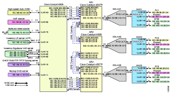
Figure 4-2 illustrates the 1-GE symmetric topology used in the solution. (See Configuration 2: N x 1-GE Asymmetric Ring.) All video traffic sources are on DER. Policy maps are applied to the ingress ports on DER in order to mark the DSCP values of the different service types. Traffic is routed through 1-GE bidirectional links, configured as IEEE 802.1q trunks that carry three VLANs: one for video, one for VoIP, and one for high-speed data (HSD). VoD traffic is also routed through 1-GE unidirectional links that use GRE tunnels for bidirectional connectivity. Multiple OSPF processes are used for the routing protocol. One or two processes advertise routes for the video-related interfaces, and second advertises routes for the VoIP-related interfaces. HSD is carried around the ring on Layer 2.
Figure 4-2 1-GE Asymmetric Topology
The switches in Figure 4-2 use the line cards, hardware versions, and IOS versions listed in Table 4-1.
Table 4-5 lists VLANs, their descriptions (service types), and IP addresses, for the DER and ARs in Figure 4-1.
Table 4-6 lists loopback addresses and endpoints for the topology, and describes the associated tunnels.
Table 4-3 lists the parameters used to configure the home access gateway (HAG). They are the same as those for the 10-GE symmetric topology.
Note
Configuring DER
This section addresses the configuration required on the switch labeled DER in Figure 4-2, to route multiple services from that switch to the ARs.
Note
This section addresses the following:
•
•
•
Note
Configuring QoS on DER
This section presents the following topics:
•
•
Note
Overview of QoS on a Cisco 7600 Series and Cisco Catalyst 6500 Series
This section addresses the configuration of quality of service (QoS) on the DER, through marking, classification, mapping, and queueing, to provide different degrees of quality of service for the different types of services supported by the solution architecture. For example, it is important to ensure the expeditious delivery of video and VoIP traffic, while providing only best-effort delivery for high-speed data (HSD).
By default, the Cisco 7600 series router and Cisco Catalyst 6500 series switch do not trust the incoming QoS markings, and therefore rewrite these bits with zeros. In this solution, packets at the network ingress ports are identified, classified, and marked according to type of traffic. The packets are marked with one of 64 possible Differentiated Services Code Point (DSCP) values at the ingress ports. These in turn are internally mapped to one of eight possible Class of Service (CoS) values, because CoS is used to determine the appropriate transmit queue for each packet. Queueing is configured on the individual 1-GE interfaces.
Note
http://www.cisco.com/warp/public/cc/pd/iosw/iore/tech/osfea_wp.htmConfiguring Marking and Classification on DER
Do the following to enable marking and classification on DER.
Step 1
mls qosStep 2
ip access-list extended acl_HSDpermit ip 192.168.90.0 0.0.0.255 anyip access-list extended acl_VoD_signalingremark Identify VoD signaling trafficpermit ip host 192.168.10.102 anypermit ip host 192.168.10.103 anyip access-list extended acl_VoIPremark Identify VoIP trafficpermit ip 192.168.80.0 0.0.0.255 anyip access-list extended acl_video_VoD_highremark Identify high priority VoD trafficpermit udp 192.168.60.0 0.0.0.255 192.168.110.0 0.0.0.255 range 5000 9000permit udp 192.168.60.0 0.0.0.255 192.168.120.0 0.0.0.255 range 5000 9000permit udp 192.168.60.0 0.0.0.255 192.168.130.0 0.0.0.255 range 5000 9000ip access-list extended acl_video_VoD_lowremark Identify low priority VoD trafficpermit udp 192.168.60.0 0.0.0.255 192.168.110.0 0.0.0.255 range 1000 4999permit udp 192.168.60.0 0.0.0.255 192.168.120.0 0.0.0.255 range 1000 4999permit udp 192.168.60.0 0.0.0.255 192.168.130.0 0.0.0.255 range 1000 4999ip access-list extended acl_video_broadcastremark Identify broadcast video traffic (multicast)permit ip 192.168.70.0 0.0.0.255 232.0.0.0 0.255.255.255Step 3
class-map match-all class_VoIPmatch access-group name acl_VoIPclass-map match-all class_video_VoD_highmatch access-group name acl_video_VoD_highclass-map match-all class_video_VoD_lowmatch access-group name acl_video_VoD_lowclass-map match-all class_video_broadcastmatch access-group name acl_video_broadcastclass-map match-all class_VoD_signalingmatch access-group name acl_VoD_signalingclass-map match-all class_HSDmatch access-group name acl_HSDStep 4
policy-map setDSCPdescription Mark DSCP values for ingress trafficclass class_VoIPset dscp efclass class_HSDset dscp defaultclass class_VoD_signalingset dscp cs3class class_video_broadcastset dscp af41class class_video_VoD_highset dscp af42class class_video_VoD_lowset dscp af43Step 5
service-policy input setDSCP
Note
Step 6
mls qos trust dscpConfiguring Mapping on DER
Do the following to configure mapping on DER.
Step 1
Note
Note
DER# show mls qos maps dscp-cosDscp-cos map: (dscp= d1d2)d1 : d2 0 1 2 3 4 5 6 7 8 9-------------------------------------0 : 00 00 00 00 00 00 00 00 01 011 : 01 01 01 01 01 01 02 02 02 022 : 02 02 02 02 03 03 03 03 03 033 : 03 03 04 04 04 04 04 04 04 044 : 05 05 05 05 05 05 05 05 06 065 : 06 06 06 06 06 06 07 07 07 076 : 07 07 07 07This table shows the following mappings:
HSD
0
0
VoD low priority
34
4
VoD high priority
36
4
VoD OOB
24
3
Broadcast video
38
4
VoIP
46
5
Step 2
The solution specifies the following DSCP-to CoS-mappings:
HSD
0
0
VoD low priority
38
1
VoD high priority
36
2
VoD OOB
24
3
Broadcast video
34
4
VoIP
46
5
a.
mls qos map dscp-cos 36 to 2mls qos map dscp-cos 38 to 1b.
DER# show mls qos maps dscp-cosDSCP-CoS Mapping Table (dscp = d1d2)d1 : d2 0 1 2 3 4 5 6 7 8 9-------------------------------------0 : 00 00 00 00 00 00 00 00 01 011 : 01 01 01 01 01 01 02 02 02 022 : 02 02 02 02 03 03 03 03 03 033 : 03 03 04 04 04 04 02 04 01 044 : 05 05 05 05 05 05 05 05 06 065 : 06 06 06 06 06 06 07 07 07 076 : 07 07 07 07Establishing and Configuring Interfaces on DER
Refer to Figure 4-2.
This section addresses the following:
•
•
•
Establishing VLANs for Services on DER
Before the 1-GE interfaces can be configured, VLANs for the various services must be created. With the exception of VLAN 90 (high-speed data), these are all Layer 3 VLANs. (Refer to Table 4-5.)
The following is configured on DER.
Tip
Step 1
a.
vlan 10name VLAN_10_Managementb.
interface Vlan10description Management VLAN (VoD signaling, DNS, DHCP, etc)ip address 192.168.10.1 255.255.255.0no ip redirectsno ip unreachablesc.
load-interval 30d.
Backup DNS server
vlan 11name VLAN_11_Managementinterface Vlan11description Management VLAN (Backup DNS)ip address 192.168.11.1 255.255.255.0no ip redirectsno ip unreachablesload-interval 30Unicast video aggregation
vlan 60name VLAN_60_Unicast_Videointerface Vlan60description VoD server VLAN (Unicast Video)ip address 192.168.60.1 255.255.255.0no ip redirectsno ip unreachablesload-interval 30VoIP
vlan 80name VLAN_80_VoIPinterface Vlan80description VoIP ingress/egress VLANip address 192.168.80.1 255.255.255.0no ip redirectsno ip unreachablesload-interval 30Step 2
a.
vlan 70name VLAN_70_Multicast_Videob.
interface Vlan70description Broadcast video source VLAN (Multicast Video)ip address 192.168.70.1 255.255.255.0no ip redirectsno ip unreachablesc.
ip pim sparse-moded.
load-interval 30Step 3
vlan 90name VLAN_90_HSDStep 4
a.
vlan 800name VLAN_800_VoIP_to/from_AR1b.
interface Vlan800description VoIP transport to/from AR1ip address 192.168.252.1 255.255.255.252c.
ip ospf network point-to-pointip ospf hello-interval 1
Note
d.
load-interval 30e.
vlan 816name VoIP transport to/from AR3interface Vlan816description VoIP transport to/from AR3ip address 192.168.252.17 255.255.255.252ip ospf network point-to-pointip ospf hello-interval 1load-interval 30Step 5
a.
vlan 900name VLAN_900_Video_to/from_AR1b.
interface Vlan900description Video transport VLAN to/from AR1ip address 192.168.254.1 255.255.255.252c.
ip pim sparse-moded.
ip ospf network point-to-pointip ospf hello-interval 1e.
load-interval 30f.
vlan 916name Video_transport_to/from_AR3interface Vlan916description Video transport VLAN to/from AR3ip address 192.168.254.17 255.255.255.252ip pim sparse-modeip ospf network point-to-pointip ospf hello-interval 1load-interval 30Establishing Interfaces for Servers, HSD, and Management on DER
VoD servers, high-speed data sources, and management resources connect to Layer 2 interfaces on DER, and their traffic is aggregated into the appropriate service VLANs.
The following is configured on DER.
Step 1
a.
interface GigabitEthernet1/1description High speed data ingress/egress portno ip addressb.
switchportswitchport access vlan 90switchport mode accessc.
load-interval 30d.
no cdp enablee.
spanning-tree portfastf.
spanning-tree bpduguard enable
Note
g.
service-policy input setDSCPStep 2
VoIP traffic
interface GigabitEthernet2/1description VoIP traffic ingress/egress portswitchport access vlan 80Ingress multicast broadcast video
interface GigabitEthernet2/9description Broadcast video source (multicast 232.1.1.1 - 232.1.1.10)switchport access vlan 70Management for the Kasenna LR server
interface GigabitEthernet2/17description Management port from Kasenna LR Server (Eth0)switchport access vlan 10Management for the Kasenna VoD pump
interface GigabitEthernet2/18description Kasenna VoD Pump Managementswitchport access vlan 10Ingress unicast video from the Kasenna VoD pump (1)
interface GigabitEthernet2/19description Unicast video from Kasenna VoD Pump (HPN0)switchport access vlan 60
Note
Ingress unicast video from the Kasenna VoD pump (2)
interface GigabitEthernet2/20description Unicast video from Kasenna VoD Pump (HPN1)switchport access vlan 60Backup DNS server
interface GigabitEthernet2/48description Backup DNS serverswitchport access vlan 11Primary DNS, DHCP, NTP, TFTP, and Syslog servers
interface GigabitEthernet5/2description Primary DNS/DHCP/NTP/TFTP/Syslog serversswitchport access vlan 10
Note
media-type rj45Establishing Bidirectional and Unidirectional Interfaces for Transport on DER
The 1-GE interfaces create the ring topology from the DER through the ARs and back to the DER. Both bidirectional and unidirectional trunking interfaces and VoD unidirectional transport are established.
The following is configured on DER.
Step 1
a.
interface GigabitEthernet7/1description Transport to/from AR1 (Gig3/1)switchportswitchport mode trunkdampeningno ip addresscarrier-delay msec 0b.
switchport trunk encapsulation dot1qc.
switchport trunk allowed vlan 90,800,900d.
load-interval 30Step 2
Note
a.
b.
wrr-queue cos-map 1 1 0wrr-queue cos-map 2 1 1wrr-queue cos-map 2 2 2 3 4 6 7
Note
c.
d.
TxQueue1 uses Weighted Random Early Drop (WRED) for queue-congestion management. Only HSD is queued in this queue, and when the amount of HSD in the queue reaches 75%, random packets are dropped in an attempt to keep the queue from reaching 100% utilization.
wrr-queue random-detect min-threshold 1 75 100wrr-queue random-detect max-threshold 1 100 100TxQueue2 uses tail drop for queue congestion management. Low-priority VoD is assigned to the first threshold and is dropped once the queue reaches 50% utilization. High-priority VoD is assigned to the second threshold and is dropped once the queue reaches 85% utilization. VoD signaling, network signaling, and broadcast video are assigned to the third threshold and is dropped once the queue reaches 100% utilization.
wrr-queue random-detect min-threshold 2 50 100wrr-queue random-detect max-threshold 2 50 100e.
The weighted queues need to be modified to handle our modified TxQueue mappings. The ratio between TxQueue2 and TxQueue1 is 255/64 = 4, so TxQueue2 needs four times as much bandwidth as TxQueue1. Therefore, TxQueue1 is allocated 20% of the bandwidth on the interface, and TxQueue2 is allocated 80% of the bandwidth.
wrr-queue bandwidth 64 255f.
Each line card has a limited amount of buffer for the transmit queues. For this interface, 40% of the buffer is allocated for TxQueue1, and 50% of the buffer is allocated for TxQueue2.
wrr-queue queue-limit 40 50g.
mls qos trust dscpStep 3
interface GigabitEthernet7/9description Transport to/from AR3 (Gig3/1)switchportswitchport trunk encapsulation dot1qswitchport trunk allowed vlan 90,816,916switchport mode trunkdampeningno ip addressload-interval 30carrier-delay msec 0wrr-queue bandwidth 64 255wrr-queue queue-limit 40 50wrr-queue random-detect min-threshold 1 75 100wrr-queue random-detect min-threshold 2 50 100wrr-queue random-detect max-threshold 1 100 100wrr-queue random-detect max-threshold 2 50 100wrr-queue cos-map 1 1 0wrr-queue cos-map 2 1 1wrr-queue cos-map 2 2 2 3 4 6 7mls qos trust dscpStep 4
a.
interface GigabitEthernet7/3description VoD transport to AR1 (Gig3/3)dampeningip address 192.168.253.1 255.255.255.252b.
ip ospf network point-to-pointip ospf hello-interval 1c.
load-interval 30d.
speed nonegotiatee.
unidirectional send-onlyf.
Second VoD transport interface to AR1
interface GigabitEthernet7/4description VoD transport to AR1 (Gig3/4)ip address 192.168.253.5 255.255.255.252Third VoD transport interface to AR1
interface GigabitEthernet7/5description VoD transport to AR1 (Gig3/5)ip address 192.168.253.9 255.255.255.252Fourth VoD interface to AR1
interface GigabitEthernet7/6description VoD transport to AR1 (Gig3/6)ip address 192.168.253.13 255.255.255.252First VoD interface to AR3
interface GigabitEthernet7/11description VoD transport to AR1 (Gig3/3)ip address 192.168.253.49 255.255.255.252Second VoD interface to AR3
interface GigabitEthernet7/12description VoD transport to AR1 (Gig3/4)ip address 192.168.253.53 255.255.255.252Third VoD interface to AR3
interface GigabitEthernet7/13description VoD transport to AR1 (Gig3/5)ip address 192.168.253.57 255.255.255.252Fourth VoD interface to AR3
interface GigabitEthernet7/14description VoD transport to AR1 (Gig3/6)ip address 192.168.253.61 255.255.255.252Establishing Tunnels on DER
The following is configured on DER.
Step 1
interface Loopback0description Endpoint for Tunnel0ip address 10.10.10.1 255.255.255.255Step 2
interface Tunnel0description Rx-side of Tx-only Gig7/3no ip addressStep 3
tunnel source 10.10.10.1tunnel destination 10.10.10.2Step 4
tunnel udlr receive-only GigabitEthernet7/3Step 5
Configuring OSPF Routing for Video and Voice Traffic on DER
There are a number of ways to configure the routing of the multiple services across the 1-GE asymmetric topology. HSD, VoIP, broadcast video, and VoD signaling can be routed across the bidirectional links, while VoD traffic can be routed across both the bidirectional and unidirectional links, or just across the unidirectional links.
In this example, HSD, VoIP, broadcast video, and VoD signaling are routed across the bidirectional links. To accomplish this, the bidirectional link is a trunk that carries three VLANs (90, 8xx, and 9xx). Because VLAN 90 is at Layer 2 around the network, there is no OSPF configuration for HSD. VoIP-related interfaces are advertised across the 8xx VLANs. Broadcast video is multicast, so the path is built from the receiver to the source. Because the DER does not need to know how to route to the destination for broadcast video, we only need to advertise the broadcast video sources across the 9xx VLANs, so that the receivers can build the reverse path back to the broadcast video source. VoD signaling is lower-bitrate, bidirectional traffic, but we still want this traffic to travel across the bidirectional transport links, rather than through the GRE tunnels associated with the unidirectional transport links. To accomplish this, we advertise the VoD server-related interfaces across the 9xx VLANs. In addition, the loopback interfaces that serve as the endpoints of the GRE tunnels for the unidirectional links are also advertised on the 9xx VLANs.
Finally, in this example the VoD traffic is routed across the unidirectional transport links only. VoD traffic is routed from the source to the receivers, so the DER must know how to route to the receivers. To accomplish this, no interfaces need to be advertised from the DER, but the DER needs a routing process associated with the unidirectional transport links to receive routing advertisements for the video aggregation VLANs on the ARs.
Three Open Shortest Path First (OSPF) routing processes must be established:
•
•
•
Routing advertisements are enabled on the transport VoD network, but are turned off on the aggregation VLANs by means of the passive-interface command.
The following is configured on DER.
Step 1
router ospf 100router-id 1.1.1.1log-adjacency-changesa.
timers throttle spf 10 100 1000b.
timers throttle lsa all 1 10 1000c.
timers lsa arrival 100If an instance of the same LSA arrives sooner than the interval that is set, the LSA is dropped.
d.
passive-interface Vlan10passive-interface Vlan11passive-interface Vlan60passive-interface Vlan70e.
network 10.10.10.0 0.0.0.255 area 0network 192.168.10.0 0.0.1.255 area 0network 192.168.60.0 0.0.0.255 area 0network 192.168.70.0 0.0.0.255 area 0network 192.168.254.0 0.0.0.255 area 0Step 2
router ospf 101router-id 1.1.1.2log-adjacency-changestimers throttle spf 10 100 1000timers throttle lsa all 1 10 1000timers lsa arrival 100passive-interface Vlan80network 192.168.80.0 0.0.0.255 area 0network 192.168.252.0 0.0.0.255 area 0maximum-paths 8Step 3
router ospf 102router-id 1.1.1.3log-adjacency-changestimers throttle spf 10 100 1000timers throttle lsa all 1 10 1000timers lsa arrival 100network 192.168.253.0 0.0.0.255 area 0maximum-paths 8Configuring Spanning Tree on DER
Because VLAN 90 is at Layer 2 around the 1-GE ring, Spanning Tree Protocol (STP) is needed to guard against loops. To improve convergence time, the four switches are configured for IEEE 802.1w Rapid Spanning Tree Protocol (RTSP), with the root at DER.
Do the following in global configuration mode to configure spanning tree parameters on DER.
Step 1
a.
spanning-tree vlan 90 root primaryor
b.
spanning-tree vlan 90 priority 24576Step 2
spanning-tree mode rapid-pvstStep 3
no spanning-tree vlan 800, 816, 900, 916Configuring AR1
This section addresses the configuration required on the switch labeled AR1 in Figure 4-2, to route multiple services from AR1 to DER and AR2.
This section addresses the following:
•
•
•
Note
Configuring QoS on AR1
See Overview of QoS on a Cisco 7600 Series and Cisco Catalyst 6500 Series.
This section presents the following topics:
•
•
Note
Overview of QoS on a Cisco Catalyst 4500 Series
This section addresses the configuration of quality of service (QoS) on AR2, through marking, classification, mapping, and queueing, to provide different degrees of quality of service for the different types of services supported by the solution architecture. For example, it is important to ensure the expeditious delivery of video and VoIP traffic, while providing only best-effort delivery for high-speed data (HSD).
By default, the Cisco Catalyst 4500 series switches (including the Cisco Catalyst 4948-10GE) do not trust the incoming QoS markings, and therefore rewrite these bits with zeros. In this solution, packets at the network ingress ports are identified, classified, and marked according to type of traffic. The packets are marked with one of 64 possible Differentiated Services Code Point (DSCP) values at the ingress ports. These in turn are internally mapped to one of eight possible Class of Service (CoS) values. The DSCP values are used to determine the appropriate transmit queue for each packet.
Configuring Marking and Classification on AR1
Do the following to enable marking and classification on AR1.
Step 1
qosStep 2
ip access-list extended acl_HSDremark Identify HSD trafficpermit ip 192.168.90.0 0.0.0.255 anyip access-list extended acl_VoD_signalingremark Identify VoD signaling trafficpermit ip 192.168.110.0 0.0.0.255 192.168.10.102permit ip 192.168.110.0 0.0.0.255 192.168.10.103ip access-list extended acl_VoIPremark Identify VoIP trafficpermit ip 192.168.111.0 0.0.0.255 anyStep 3
class-map match-all class_VoIPmatch access-group name acl_VoIPclass-map match-all class_VoD_signalingmatch access-group name acl_VoD_signalingclass-map match-all class_HSDmatch access-group name acl_HSDStep 4
policy-map setDSCPdescription Mark DSCP values for ingress trafficclass class_VoIPset dscp efclass class_HSDset dscp defaultclass class_VoD_signalingset dscp cs3Step 5
service-policy input setDSCP
Note
Step 6
qos trust dscpConfiguring Mapping on AR1
Do the following to configure mapping on AR1.
Step 1
Note
Note
AR2# show qos maps dscpDSCP-CoS Mapping Table (dscp = d1d2)d1 : d2 0 1 2 3 4 5 6 7 8 9-------------------------------------0 : 00 00 00 00 00 00 00 00 01 011 : 01 01 01 01 01 01 02 02 02 022 : 02 02 02 02 03 03 03 03 03 033 : 03 03 04 04 04 04 04 04 04 044 : 05 05 05 05 05 05 05 05 06 065 : 06 06 06 06 06 06 07 07 07 076 : 07 07 07 07This table shows the following mappings:
HSD
0
0
VoD low priority
34
4
VoD high priority
36
4
VoD OOB
24
3
Broadcast video
38
4
VoIP
46
5
Step 2
The solution specifies the following DSCP-to CoS-mappings:
HSD
0
0
VoD low priority
38
1
VoD high priority
36
2
VoD OOB
24
3
Broadcast video
34
4
VoIP
46
5
a.
qos map dscp 38 to cos 1qos map dscp 36 to cos 2b.
AR2# show qos maps dscpDSCP-CoS Mapping Table (dscp = d1d2)d1 : d2 0 1 2 3 4 5 6 7 8 9-------------------------------------0 : 00 00 00 00 00 00 00 00 01 011 : 01 01 01 01 01 01 02 02 02 022 : 02 02 02 02 03 03 03 03 03 033 : 03 03 04 04 04 04 02 04 01 044 : 05 05 05 05 05 05 05 05 06 065 : 06 06 06 06 06 06 07 07 07 076 : 07 07 07 07Configuring Queueing on AR1
Unlike the Cisco 7600 series and Cisco Catalyst 6500 series, the Cisco Catalyst 4500 series uses the same queueing on all interfaces. Queueing is configured globally.
Do the following to change the DSCP-to-TxQueue mappings on AR1.
Step 1
DSCP-TxQueue Mapping Table (dscp = d1d2)d1 : d2 0 1 2 3 4 5 6 7 8 9-------------------------------------0 : 01 01 01 01 01 01 01 01 01 011 : 01 01 01 01 01 01 02 02 02 022 : 02 02 02 02 02 02 02 02 02 023 : 02 02 03 03 03 03 03 03 03 034 : 03 03 03 03 03 03 03 03 04 045 : 04 04 04 04 04 04 04 04 04 046 : 04 04 04 04Step 2
qos map dscp 34 36 38 48 49 50 51 52 to tx-queue 2qos map dscp 53 54 55 56 57 58 59 60 to tx-queue 2qos map dscp 61 62 63 to tx-queue 2Step 3
DSCP-TxQueue Mapping Table (dscp = d1d2)d1 : d2 0 1 2 3 4 5 6 7 8 9-------------------------------------0 : 01 01 01 01 01 01 01 01 01 011 : 01 01 01 01 01 01 02 02 02 022 : 02 02 02 02 02 02 02 02 02 023 : 02 02 03 03 02 03 02 03 02 034 : 03 03 03 03 03 03 03 03 02 025 : 02 02 02 02 02 02 02 02 02 026 : 02 02 02 02Step 4
TxQueue1 uses Weighted Random Early Drop (WRED) for queue-congestion management. Only HSD is queued in this queue, and when the amount of HSD in the queue reaches 75%, random packets are dropped in an attempt to keep the queue from reaching 100% utilization.
wrr-queue threshold 1 100 100 100 100 100 100 100 100wrr-queue random-detect min-threshold 1 75 100 100 100 100 100 100 100wrr-queue random-detect max-threshold 1 100 100 100 100 100 100 100 100TxQueue2 uses tail drop for queue congestion management. Low-priority VoD is assigned to the first threshold and is dropped once the queue reaches 45% utilization. High-priority VoD is assigned to the second threshold and is dropped once the queue reaches 85% utilization. VoD signaling, network signaling, and broadcast video are assigned to the third threshold and is dropped once the queue reaches 100% utilization.
wrr-queue threshold 2 45 85 100 100 100 100 100 100no wrr-queue random-detect 2Step 5
The weighted queues need to be modified to handle our modified TxQueue mappings. The ratio between TxQueue2 and TxQueue1 is 255/64 = 4, so TxQueue2 needs four times as much bandwidth as TxQueue1. Therefore, TxQueue1 is allocated 20% of the bandwidth on the interface, and TxQueue2 is allocated 80% of the bandwidth.
wrr-queue bandwidth 64 255 0 0 0 0 0Step 6
Each line card has a limited amount of buffer for the transmit queues. For this interface, 40% of the buffer is allocated for TxQueue1, and 50% of the buffer is allocated for TxQueue2.
wrr-queue queue-limit 40 50 0 0 0 0 0Establishing and Configuring Interfaces on AR1
Refer to Figure 4-2.
This section addresses the following:
•
•
•
Establishing VLANs for Services on AR1
Before bidirectional and unidirectional transport interfaces can be configured, VLANs for the various services must be created. With the exception of VLAN 90 (high-speed data), these are all Layer 3 VLANs. (Refer to Table 4-2.)
The following is configured on AR1.
Note
Step 1
vlan 90name VLAN_90_HSDStep 2
a.
vlan 110name VLAN_110_Videob.
interface Vlan110description Video edge VLANip address 192.168.110.1 255.255.255.0no ip redirectsno ip unreachablesc.
ip pim sparse-moded.
ip igmp static-group 232.1.1.1 source ssm-mapip igmp static-group 232.1.1.2 source ssm-mapip igmp static-group 232.1.1.3 source ssm-mapip igmp static-group 232.1.1.4 source ssm-mapip igmp static-group 232.1.1.5 source ssm-mapip igmp static-group 232.1.1.6 source ssm-mapip igmp static-group 232.1.1.7 source ssm-mapip igmp static-group 232.1.1.8 source ssm-mapip igmp static-group 232.1.1.9 source ssm-mapip igmp static-group 232.1.1.10 source ssm-mape.
load-interval 30f.
arp timeout 250
Note
Step 3
a.
vlan 111name VLAN_111_VoIPb.
interface Vlan111description VoIP edge VLANip address 192.168.111.1 255.255.255.0no ip redirectsno ip unreachablesload-interval 30Step 4
a.
vlan 800name VLAN_800_VoIP_to/from_DERb.
interface Vlan800description VoIP transport VLAN to/from DERip address 192.168.252.2 255.255.255.252c.
ip ospf network point-to-pointip ospf hello-interval 1d.
load-interval 30Step 5
a.
vlan 808name VLAN_808_VoIP_to/from_AR2b.
interface Vlan808description VoIP transport to/from AR2ip address 192.168.252.9 255.255.255.252ip ospf network point-to-pointip ospf hello-interval 1load-interval 30Step 6
a.
vlan 900name VLAN_900_Video_to/from_DERb.
interface Vlan900description Video transport VLAN to/from DERip address 192.168.254.2 255.255.255.252c.
ip pim sparse-moded.
ip ospf network point-to-pointip ospf hello-interval 1e.
load-interval 30Step 7
a.
vlan 908name VLAN_908_Video_to/from_AR2b.
interface Vlan908description Video transport VLAN to/from AR2ip address 192.168.254.9 255.255.255.252ip pim sparse-modeip ospf network point-to-pointip ospf hello-interval 1load-interval 30Establishing Bidirectional and Unidirectional Transport Interfaces on AR1
Bidirectional and unidirectional transport interfaces must be established between AR1 and DER and AR2.
The following is configured on AR1.
Note
Step 1
a.
interface GigabitEthernet3/1description Transport to/from DER (Gig7/1)switchport trunk encapsulation dot1qswitchport trunk allowed vlan 90,800,900switchport mode trunkdampeningload-interval 30carrier-delay msec 0b.
qos trust dscpc.
tx-queue 1bandwidth percent 19tx-queue 2bandwidth percent 80tx-queue 3priority hightx-queue 4bandwidth percent 1d.
interface GigabitEthernet4/3description Transport to/from AR2 (Gig1/1)switchport trunk encapsulation dot1qswitchport trunk allowed vlan 90,808,908switchport mode trunkdampeningload-interval 30carrier-delay msec 0qos trust dscptx-queue 1bandwidth percent 19tx-queue 2bandwidth percent 80tx-queue 3priority hightx-queue 4bandwidth percent 1Step 2
a.
interface GigabitEthernet3/3description Transport from DER (Gig7/3)no switchportdampeningip address 192.168.253.2 255.255.255.252ip ospf network point-to-pointip ospf hello-interval 1load-interval 30carrier-delay msec 0qos trust dscpb.
speed nonegotiatec.
unidirectional receive-only
Note
d.
Second unidirectional transport from DER
interface GigabitEthernet3/4description Transport from DER (Gig7/4)no switchportdampeningip address 192.168.253.6 255.255.255.252ip ospf network point-to-pointip ospf hello-interval 1load-interval 30carrier-delay msec 0speed nonegotiateqos trust dscpunidirectional receive-onlyThird unidirectional transport from DER
interface GigabitEthernet3/5description Transport from DER (Gig7/5)no switchportdampeningip address 192.168.253.10 255.255.255.252ip ospf network point-to-pointip ospf hello-interval 1load-interval 30carrier-delay msec 0speed nonegotiateqos trust dscpunidirectional receive-onlyFourth unidirectional transport from DER
description Transport from DER (Gig7/6)no switchportdampeningip address 192.168.253.14 255.255.255.252ip ospf network point-to-pointip ospf hello-interval 1load-interval 30carrier-delay msec 0speed nonegotiateqos trust dscpunidirectional receive-onlyStep 3
a.
interface GigabitEthernet4/4description Transport to AR2 (Gig1/2)no switchportdampeningip address 192.168.253.25 255.255.255.252ip ospf network point-to-pointip ospf hello-interval 1load-interval 30carrier-delay msec 0speed nonegotiateqos trust dscptx-queue 1bandwidth percent 19tx-queue 2bandwidth percent 80tx-queue 3priority hightx-queue 4bandwidth percent 1b.
unidirectional send-onlyc.
interface GigabitEthernet4/5description Transport to AR2 (Gig1/3)no switchportdampeningip address 192.168.253.29 255.255.255.252ip ospf network point-to-pointip ospf hello-interval 1load-interval 30carrier-delay msec 0speed nonegotiateqos trust dscptx-queue 1bandwidth percent 19tx-queue 2bandwidth percent 80tx-queue 3priority hightx-queue 4bandwidth percent 1unidirectional send-onlyEstablishing Tunnels on AR1
See Establishing Tunnels on DER.
Table 4-8 lists the loopback interfaces and corresponding tunnel interfaces configured on AR1.
Establishing an Interface to a DSLAM on AR1
Do the following to establish an interface to DSLAM1.
The following is configured on AR1.
Step 1
a.
interface GigabitEthernet5/1description GigE trunk to/from DSLAM uplink GigEswitchport trunk encapsulation dot1qswitchport trunk allowed vlan 90,110,111switchport mode trunkb.
switchport block unicast
Note
c.
service-policy input setDSCPd.
load-interval 30e.
tx-queue 1bandwidth percent 19tx-queue 2bandwidth percent 80tx-queue 3priority hightx-queue 4bandwidth percent 1f.
no cdp enableg.
spanning-tree portfast trunkStep 2
Configuring OSPF Routing for Video and Voice Traffic on AR1
Refer to Configuring OSPF Routing for Video and Voice Traffic on DER.
The following is configured on AR1.
Step 1
router ospf 100router-id 2.2.2.1log-adjacency-changestimers throttle spf 10 100 1000timers throttle lsa all 1 10 1000timers lsa arrival 100network 10.10.10.0 0.0.0.255 area 0network 192.168.254.0 0.0.0.255 area 0maximum-paths 8Step 2
router ospf 101router-id 2.2.2.2log-adjacency-changestimers throttle spf 10 100 1000timers throttle lsa all 1 10 1000timers lsa arrival 100passive-interface Vlan111network 192.168.111.0 0.0.0.255 area 0network 192.168.252.0 0.0.0.255 area 0maximum-paths 8Step 3
router ospf 102router-id 2.2.2.3log-adjacency-changestimers throttle spf 10 100 1000timers throttle lsa all 1 10 1000timers lsa arrival 100passive-interface Vlan110network 192.168.110.0 0.0.0.255 area 0network 192.168.253.0 0.0.0.255 area 0maximum-paths 8Configuring Spanning Tree on AR1
See Configuring Spanning Tree on DER.
The following is configured on AR1.
Step 1
spanning-tree mode rapid-pvstStep 2
no spanning-tree vlan 800, 808, 900, 908Configuring AR2
This section addresses the configuration required on the switch labeled AR2 in Figure 4-2, to route multiple services from AR2 to DER, AR1, and AR3.
Note
This section addresses the following:
•
•
•
Note
Configuring QoS on AR2
See Overview of QoS on a Cisco 7600 Series and Cisco Catalyst 6500 Series.
This section presents the following topics:
•
Note
Configuring Marking and Classification on AR2
Do the following to enable marking and classification on AR2.
Step 1
mls qosStep 2
ip access-list extended acl_HSDremark Identify HSD trafficpermit ip 192.168.90.0 0.0.0.255 anyip access-list extended acl_VoD_signalingremark Identify VoD signaling trafficpermit ip 192.168.120.0 0.0.0.255 192.168.10.102permit ip 192.168.120.0 0.0.0.255 192.168.10.103ip access-list extended acl_VoIPremark Identify VoIP trafficpermit ip 192.168.121.0 0.0.0.255 anyStep 3
class-map match-all class_VoIPmatch access-group name acl_VoIPclass-map match-all class_VoD_signalingmatch access-group name acl_VoD_signalingclass-map match-all class_HSDmatch access-group name acl_HSDStep 4
policy-map setDSCPdescription Mark DSCP values for ingress trafficclass class_VoIPset dscp efclass class_HSDset dscp defaultclass class_VoD_signalingset dscp cs3Step 5
service-policy input setDSCP
Note
Step 6
mls qos trust dscpConfiguring Mapping on AR2
To configure mapping on AR2, refer to Configuring Mapping on DER.
Establishing and Configuring Interfaces on AR2
Refer to Figure 4-2.
This section addresses the following:
•
•
•
Establishing VLANs for Services on AR2
Before bidirectional and unidirectional transport interfaces can be configured, VLANs for the various services must be created. With the exception of VLAN 90 (high-speed data), these are all Layer 3 VLANs. (Refer to Table 4-2.)
The following is configured on AR2.
Note
Step 1
vlan 90name VLAN_90_HSDStep 2
a.
vlan 120name VLAN_120_Videob.
interface Vlan120description Video edge VLANip address 192.168.120.1 255.255.255.0no ip redirectsno ip unreachablesc.
ip pim sparse-moded.
ip igmp static-group 232.1.1.1 source ssm-mapip igmp static-group 232.1.1.2 source ssm-mapip igmp static-group 232.1.1.3 source ssm-mapip igmp static-group 232.1.1.4 source ssm-mapip igmp static-group 232.1.1.5 source ssm-mapip igmp static-group 232.1.1.6 source ssm-mapip igmp static-group 232.1.1.7 source ssm-mapip igmp static-group 232.1.1.8 source ssm-mapip igmp static-group 232.1.1.9 source ssm-mapip igmp static-group 232.1.1.10 source ssm-mape.
load-interval 30f.
arp timeout 250
Note
Step 3
a.
vlan 121name VLAN_121_VoIPb.
interface Vlan121description VoIP edge VLANip address 192.168.121.1 255.255.255.0no ip redirectsno ip unreachablesc.
load-interval 30Step 4
a.
vlan 808name VLAN_808_VoIP_to/from_AR1b.
interface Vlan808description VoIP transport VLAN to/from AR1ip address 192.168.252.10 255.255.255.252c.
load-interval 30d.
ip ospf network point-to-pointip ospf hello-interval 1Step 5
vlan 812name VLAN_812_VoIP_to/from_AR3interface Vlan812description VoIP transport VLAN to/from AR3ip address 192.168.252.14 255.255.255.252ip ospf network point-to-pointip ospf hello-interval 1load-interval 30Step 6
a.
vlan 908name VLAN_912_Video_to/from_DERb.
interface Vlan908description Video transport VLAN to/from AR1ip address 192.168.254.10 255.255.255.252c.
ip pim sparse-moded.
load-interval 30e.
ip ospf network point-to-pointip ospf hello-interval 1Step 7
vlan 912name VLAN_908_Video_to/from_AR3interface Vlan912description Video transport VLAN to/from AR3ip address 192.168.254.14 255.255.255.252ip pim sparse-modeip ospf network point-to-pointip ospf hello-interval 1load-interval 30Establishing Bidirectional and Unidirectional Transport Interfaces on AR2
Bidirectional and unidirectional transport interfaces must be established between AR1 and DER and AR2.
The following is configured on AR2.
Note
Step 1
a.
interface GigabitEthernet1/1description Transport to/from AR1 (Gig4/3)switchportswitchport trunk encapsulation dot1qswitchport trunk allowed vlan 90,808,908switchport mode trunkno ip addressload-interval 30carrier-delay msec 0b.
c.
interface GigabitEthernet1/5description Transport to/from AR3 (Gig4/3)switchportswitchport trunk encapsulation dot1qswitchport trunk allowed vlan 90,812,912switchport mode trunkdampeningno ip addressload-interval 30carrier-delay msec 0spanning-tree cost 10 <---See Note below
Note
d.
Step 2
a.
interface GigabitEthernet1/2description Transport from AR1 (Gig4/4)dampeningip address 192.168.253.26 255.255.255.252b.
ip ospf network point-to-pointip ospf hello-interval 1c.
load-interval 30
Note
d.
speed nonegotiatee.
unidirectional receive-onlyf.
Second unidirectional transport from AR1
interface GigabitEthernet1/3description Transport from AR1 (Gig4/5)dampeningip address 192.168.253.30 255.255.255.252ip ospf network point-to-pointip ospf hello-interval 1load-interval 30carrier-delay msec 0speed nonegotiatewrr-queue bandwidth 64 255wrr-queue queue-limit 40 50wrr-queue random-detect min-threshold 2 50 100wrr-queue random-detect max-threshold 1 100 100wrr-queue random-detect max-threshold 2 50 100wrr-queue cos-map 1 1 0wrr-queue cos-map 2 1 1wrr-queue cos-map 2 2 2 3 4 6 7mls qos trust dscpunidirectional receive-onlyThird unidirectional transport from AR3
interface GigabitEthernet1/6description Transport from AR3 (Gig4/4)dampeningip address 192.168.253.38 255.255.255.252ip ospf network point-to-pointip ospf hello-interval 1load-interval 30carrier-delay msec 0speed nonegotiatewrr-queue bandwidth 64 255wrr-queue queue-limit 40 50wrr-queue random-detect min-threshold 2 50 100wrr-queue random-detect max-threshold 1 100 100wrr-queue random-detect max-threshold 2 50 100wrr-queue cos-map 1 1 0wrr-queue cos-map 2 1 1wrr-queue cos-map 2 2 2 3 4 6 7mls qos trust dscpunidirectional receive-onlyFourth unidirectional transport from AR3
interface GigabitEthernet1/7description Transport from AR3 (Gig4/5)dampeningip address 192.168.253.42 255.255.255.252ip ospf network point-to-pointip ospf hello-interval 1load-interval 30carrier-delay msec 0speed nonegotiatewrr-queue bandwidth 64 255wrr-queue queue-limit 40 50wrr-queue random-detect min-threshold 2 50 100wrr-queue random-detect max-threshold 1 100 100wrr-queue random-detect max-threshold 2 50 100wrr-queue cos-map 1 1 0wrr-queue cos-map 2 1 1wrr-queue cos-map 2 2 2 3 4 6 7mls qos trust dscpunidirectional receive-onlyEstablishing Tunnels on AR2
See Establishing Tunnels on DER.
Table 4-9 lists the loopback interfaces and corresponding tunnel interfaces configured on AR2.
Establishing an Interface to a DSLAM on AR2
DSLAM2 is an Ericsson GE DSLAM. Note the differences in Step 1f.
The following is configured on AR2.
Step 1
a.
interface GigabitEthernet2/1description Ericsson DSLAMswitchportswitchport trunk encapsulation dot1qswitchport trunk allowed vlan 90,120,121switchport mode trunkno ip addressb.
switchport block unicast
Note
c.
service-policy input setDSCPd.
load-interval 30e.
no cdp enablef.
spanning-tree portfast trunkg.
wrr-queue bandwidth 64 255 0wrr-queue queue-limit 40 50 0wrr-queue threshold 1 100 100 100 100 100 100 100 100wrr-queue threshold 2 50 100 100 100 100 100 100 100wrr-queue random-detect min-threshold 1 75 100 100 100 100 100 100 100wrr-queue random-detect max-threshold 1 100 100 100 100 100 100 100 100no wrr-queue random-detect 2wrr-queue cos-map 2 1 1wrr-queue cos-map 2 2 2 3 4 6 7Step 2
Configuring OSPF Routing for Video and Voice Traffic on AR2
See Configuring OSPF Routing for Video and Voice Traffic on DER.
The following is configured on AR2.
Step 1
router ospf 100router-id 3.3.3.1log-adjacency-changestimers throttle spf 10 100 1000timers throttle lsa all 1 10 1000timers lsa arrival 100network 10.10.10.0 0.0.0.255 area 0network 192.168.254.0 0.0.0.255 area 0maximum-paths 8Step 2
router ospf 101router-id 3.3.3.2log-adjacency-changestimers throttle spf 10 100 1000timers throttle lsa all 1 10 1000timers lsa arrival 100passive-interface Vlan121network 192.168.121.0 0.0.0.255 area 0network 192.168.252.0 0.0.0.255 area 0maximum-paths 8Step 3
router ospf 102router-id 3.3.3.3log-adjacency-changestimers throttle spf 10 100 1000timers throttle lsa all 1 10 1000timers lsa arrival 100passive-interface Vlan120network 192.168.120.0 0.0.0.255 area 0network 192.168.253.0 0.0.0.255 area 0maximum-paths 8Configuring Spanning Tree on AR2
See Configuring Spanning Tree on DER.
The following is configured on AR2.
Step 1
spanning-tree mode rapid-pvstStep 2
no spanning-tree vlan 800, 812, 908, 912Configuring AR3
This section addresses the configuration required on the switch labeled AR3 in Figure 4-1, to route multiple services from AR3 to AR2 and DER.
This section addresses the following:
•
•
•
Note
Configuring QoS on AR3
See Overview of QoS on a Cisco Catalyst 4500 Series.
This section presents the following topics:
•
Note
Configuring Marking and Classification on AR3
Do the following to enable marking and classification on AR3.
Step 1
qosStep 2
ip access-list extended acl_HSDremark Identify HSD trafficpermit ip 192.168.90.0 0.0.0.255 anyip access-list extended acl_VoD_signalingremark Identify VoD signaling trafficpermit ip 192.168.130.0 0.0.0.255 192.168.10.102permit ip 192.168.130.0 0.0.0.255 192.168.10.103ip access-list extended acl_VoIPremark Identify VoIP trafficpermit ip 192.168.131.0 0.0.0.255 anyStep 3
class-map match-all class_VoIPmatch access-group name acl_VoIPclass-map match-all class_VoD_signalingmatch access-group name acl_VoD_signalingclass-map match-all class_HSDmatch access-group name acl_HSDStep 4
policy-map setDSCPdescription Mark DSCP values for ingress trafficclass class_VoIPset dscp efclass class_HSDset dscp defaultclass class_VoD_signalingset dscp cs3Step 5
service-policy input setDSCP
Note
Step 6
qos trust dscpConfiguring Mapping on AR3
To configure mapping on AR3, proceed as in Configuring Mapping on AR1.
Configuring Queueing on AR3
To configure queueing on AR3, proceed as in Configuring Queueing on AR1.
Establishing and Configuring Interfaces on AR3
Refer to Figure 4-2.
This section addresses the following:
•
•
•
Establishing VLANs for Services on AR3
Before bidirectional and unidirectional transport interfaces can be configured, VLANs for the various services must be created. With the exception of VLAN 90 (high-speed data), these are all Layer 3 VLANs. (Refer to Table 4-2.)
The following is configured on AR3.
Note
Step 1
vlan 90name VLAN_90_HSDStep 2
a.
vlan 130name VLAN_130_Videob.
interface Vlan130description Video edge VLANip address 192.168.130.1 255.255.255.0no ip redirectsno ip unreachablesc.
ip pim sparse-moded.
ip igmp static-group 232.1.1.1 source ssm-mapip igmp static-group 232.1.1.2 source ssm-mapip igmp static-group 232.1.1.3 source ssm-mapip igmp static-group 232.1.1.4 source ssm-mapip igmp static-group 232.1.1.5 source ssm-mapip igmp static-group 232.1.1.6 source ssm-mapip igmp static-group 232.1.1.7 source ssm-mapip igmp static-group 232.1.1.8 source ssm-mapip igmp static-group 232.1.1.9 source ssm-mapip igmp static-group 232.1.1.10 source ssm-mape.
load-interval 30f.
arp timeout 250
Note
Step 3
a.
vlan 131name VLAN_131_VoIPb.
interface Vlan131description VoIP edge VLANip address 192.168.131.1 255.255.255.0no ip redirectsno ip unreachablesload-interval 30Step 4
a.
vlan 812name VLAN_812_VoIP_to/from_AR2b.
interface Vlan812description VoIP transport to/from AR2ip address 192.168.252.13 255.255.255.252ip ospf network point-to-pointip ospf hello-interval 1Step 5
vlan 816name VLAN_808_VoIP_to/from_DERinterface Vlan816description VoIP transport to/from DERip address 192.168.252.18 255.255.255.252ip ospf network point-to-pointip ospf hello-interval 1Step 6
a.
vlan 912name VLAN_912_Video_to/from_AR2b.
interface Vlan912description Video transport to/from AR2ip address 192.168.254.13 255.255.255.252c.
ip pim sparse-moded.
ip ospf network point-to-pointip ospf hello-interval 1Step 7
vlan 916name VLAN_916_Video_to/from_DERinterface Vlan916description Video transport to/from DERip address 192.168.254.18 255.255.255.252ip pim sparse-modeip ospf network point-to-pointip ospf hello-interval 1Establishing Bidirectional and Unidirectional Transport Interfaces on AR3
Bidirectional and unidirectional transport interfaces must be established between AR1 and DER and AR2.
The following is configured on AR3.
Note
Step 1
a.
interface GigabitEthernet3/1description Transport to/from DER (Gig7/9)switchport trunk encapsulation dot1qswitchport trunk allowed vlan 90,816,916switchport mode trunkload-interval 30b.
qos trust dscpc.
tx-queue 1bandwidth percent 19tx-queue 2bandwidth percent 80tx-queue 3priority hightx-queue 4bandwidth percent 1d.
interface GigabitEthernet4/3description Transport to/from AR2 (Gig1/5)switchport trunk encapsulation dot1qswitchport trunk allowed vlan 90,812,912switchport mode trunkload-interval 30qos trust dscptx-queue 1bandwidth percent 19tx-queue 2bandwidth percent 80tx-queue 3priority hightx-queue 4bandwidth percent 1spanning-tree cost 10 <---See Note below
Note
Step 2
a.
interface GigabitEthernet3/3description Transport from DER (Gig7/11)dampeningip address 192.168.253.50 255.255.255.252b.
ip ospf network point-to-pointip ospf hello-interval 1c.
load-interval 30
Note
d.
speed nonegotiatee.
unidirectional receive-onlyf.
Second unidirectional transport from DER
interface GigabitEthernet3/4description Transport from DER (Gig7/12)no switchportdampeningip address 192.168.253.54 255.255.255.252ip ospf network point-to-pointip ospf hello-interval 1load-interval 30carrier-delay msec 0speed nonegotiateunidirectional receive-onlyThird unidirectional transport from DER
interface GigabitEthernet3/5description Transport from DER (Gig7/13)no switchportdampeningip address 192.168.253.58 255.255.255.252ip ospf network point-to-pointip ospf hello-interval 1load-interval 30carrier-delay msec 0speed nonegotiateqos trust dscpunidirectional receive-onlyFourth unidirectional transport from DER
interface GigabitEthernet3/6description Transport from DER (Gig7/14)no switchportdampeningip address 192.168.253.62 255.255.255.252ip ospf network point-to-pointip ospf hello-interval 1load-interval 30carrier-delay msec 0speed nonegotiateqos trust dscpunidirectional receive-onlyStep 3
a.
interface GigabitEthernet4/4description Transport to AR2 (Gig1/6)no switchportip address 192.168.253.37 255.255.255.252ip ospf network point-to-pointip ospf hello-interval 1load-interval 30speed nonegotiateqos trust dscptx-queue 1bandwidth percent 19tx-queue 2bandwidth percent 80tx-queue 3priority hightx-queue 4bandwidth percent 1b.
unidirectional send-onlyc.
interface GigabitEthernet4/5description Transport to AR2 (Gig1/7)no switchportip address 192.168.253.41 255.255.255.252ip ospf network point-to-pointip ospf hello-interval 1load-interval 30speed nonegotiateqos trust dscptx-queue 1bandwidth percent 19tx-queue 2bandwidth percent 80tx-queue 3priority hightx-queue 4bandwidth percent 1unidirectional send-onlyEstablishing Tunnels on AR3
See Establishing Tunnels on DER.
Table 4-10 lists the loopback interfaces and corresponding tunnel interfaces configured on AR3.
Establishing an Interface to a DSLAM on AR3
Do the following to establish an interface to DSLAM3.
The following is configured on AR3.
Step 1
a.
interface GigabitEthernet5/1description GigE trunk to/from DSLAM uplink GigEswitchport trunk encapsulation dot1qswitchport trunk allowed vlan 90,130,131switchport mode trunkb.
switchport block unicast
Note
c.
service-policy input setDSCPd.
load-interval 30e.
tx-queue 1bandwidth percent 19tx-queue 2bandwidth percent 80tx-queue 3priority hightx-queue 4bandwidth percent 1f.
no cdp enableg.
spanning-tree portfast trunkStep 2
Configuring OSPF Routing for Video and Voice Traffic on AR3
Refer to Configuring OSPF Routing for Video and Voice Traffic on DER.
The following is configured on AR3.
Step 1
router ospf 100router-id 4.4.4.1log-adjacency-changestimers throttle spf 10 100 1000timers throttle lsa all 1 10 1000timers lsa arrival 100network 10.10.10.0 0.0.0.255 area 0network 192.168.254.0 0.0.0.255 area 0maximum-paths 8Step 2
router ospf 101router-id 4.4.4.2log-adjacency-changestimers throttle spf 10 100 1000timers throttle lsa all 1 10 1000timers lsa arrival 100passive-interface Vlan131network 192.168.131.0 0.0.0.255 area 0network 192.168.252.0 0.0.0.255 area 0maximum-paths 8Step 3
router ospf 102router-id 4.4.4.3log-adjacency-changestimers throttle spf 10 100 1000timers throttle lsa all 1 10 1000timers lsa arrival 100passive-interface Vlan130network 192.168.130.0 0.0.0.255 area 0network 192.168.253.0 0.0.0.255 area 0maximum-paths 8Configuring Spanning Tree on AR3
See Configuring Spanning Tree on DER.
The following is configured on AR3.
Step 1
spanning-tree mode rapid-pvstStep 2
no spanning-tree vlan 812, 816, 912, 916
![]()
![]()
![]()
![]()
![]()
![]()
![]()
![]()
Posted: Wed Sep 20 09:04:37 PDT 2006
All contents are Copyright © 1992--2006 Cisco Systems, Inc. All rights reserved.
Important Notices and Privacy Statement.