|
|

Table Of Contents
Solution Transport Architecture
Distribution and Aggregation Transport Architecture
Configuration 1: 10-GE Layer 3 Symmetric Ring
Configuration 2: N x 1-GE Asymmetric Ring
Overview of DiffServ Architecture
DiffServ Architecture in the Solution
QoS in the Aggregation/Distribution Network
Solution Transport Architecture
The Cisco Gigabit-Ethernet Optimized IPTV/Video over Broadband (GOVoBB) Solution transport architecture is subdivided into recommendations for the access, aggregation, and distribution networks. While the service-separation architecture used in Release 1.0 includes requirements regarding how a home access gateway (HAG) interfaces to the home network, it does not include any recommendations for the technologies or configurations used in that network. The Release 1.0 transport architecture also does not include recommendations for the core network. Because of this, the solution test environment combines the video application components of both the super headend (SHE) and video headend office (VHO) sites into a single combined topology that connects aggregation routers (ARs) to a distribution edge router (DER).
This chapter presents the following major topics:
•
Overview
•
Overview
Figure 2-3 introduced the transport layers of the general IPTV/VoBB transport architecture (described in IPTV/VoBB Transport Architecture and Issues) that are the subject of the recommendations in this document.
While the solution transport architecture focuses on video, there is an implicit assumption that the network be able to support a full triple-play environment. Consequently, the transport architecture includes a common quality of service (QoS) architecture for video, voice, and Internet access services. Because the transport architecture is based on the service separation model described in IPTV/VoBB Transport Architecture and Issues, the actual transport architecture used for Internet access and voice services may differ from the video transport architecture described in this document.
To ensure that the video transport architecture works in a triple-play environment, solution testing included a test bed environment in which the transport network was configured to support all three services. Because solution testing was focused on video, it included the application, control, and transport environment for video services. Testing only included enough testing of the Internet access and voice services to ensure that an example forwarding architecture for these services can coexist with video, and that the common QoS architecture specified in this document meets the jitter and packet-loss requirements for each service.
Note
While the transport architecture includes configuration recommendations for all of the transport layers shown in Figure 2-3, this document only includes example configurations for the transport components that are implemented by means of Cisco products. These components are the DER and AR. Because the DER and ARs are the switching components that implement the distribution and aggregation networks, more detailed configuration information is provided for this portion of the network.
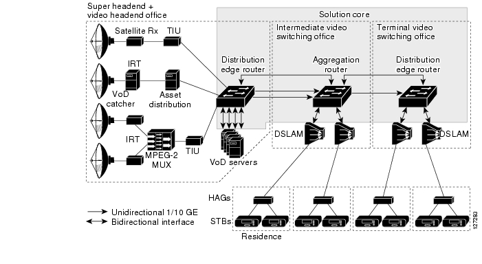
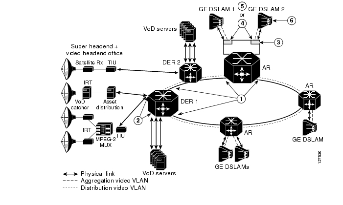
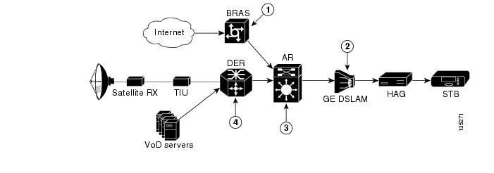
Figure 3-1 highlights that part of the transport network that is addressed by solution testing and core configuration examples.
Figure 3-1 IPTV/Video over Broadband Transport Architecture: Solution Core
Solution Components
Table 3-1 lists the network architecture components used in Release 1.0 of the solution, with additional information. For detail regarding interfaces, see the following:
Distribution and Aggregation Transport Architecture
As described in IPTV/VoBB Transport Architecture and Issues, the transport architecture uses service separation to support the capability of having separate routing and forwarding planes for different services. This functionality is used in the aggregation and distribution networks to enable a separate logical and physical transport architecture that is optimized for the delivery of video.
This section describes how the transport architecture is optimized for video. Because an important requirement of the transport architecture is that it also must support a triple-play environment, this section also describes an example distribution and aggregation network configuration for voice and Internet access.
This section presents the following topics:
Video Forwarding
This section presents the following topics related to the delivery of video services:
•
•
Layer 3 Edge for Video Services
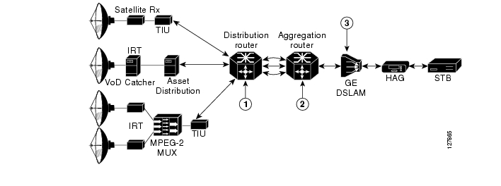
One of the primary architectural decisions that must be made in specifying a transport architecture for video services is where the Layer 3 edge of the transport network should be for video services. Figure 3-2 illustrates the points in the network where the Layer 3 edge may reside, as well as the issues and benefits associated with each location. There are three points: the DSLAM, the AR, or the DER. This section describes the issues and benefits associated with each of these options, as well as the design choice that was made for Release 1.0.
Figure 3-2 Potential Layer 3 Edge Points for Video
Table 3-2 summarizes issues and benefits for edge points 1, 2, and 3 in the above figure. The paragraphs that follow address issues to related to DSLAM-based, DER-based, and AR-based Layer 3 edge points.
DSLAM-Based Layer 3 Edge
Because of their location at the edge of the network, DSLAMs have traditionally performed Layer 2 switching functions. This has kept the function of the DSLAM fairly simple and has also made DSLAMs simple to manage. However, a Layer 3-capable DSLAM is more complex to build, and therefore more complex to manage.
Issue: DSLAM Complexity
A DSLAM that supports Layer 3 functionality must be capable of a number of functions besides Layer 3 forwarding. For example, a Layer 3-capable DSLAM must be able to support a DHCP relay function. This function requires that the IP address of a DHCP server as well as the IP subnet that the DSLAM is associated with must be configured on the DSLAM. The DSLAM must also support and be configured for IP routing protocols to enable dynamic routing from the AR.
Issue: Complex Subscriber-Address Management
An IP-capable DSLAM must have an IP subnet allocated to it to allow IP packets to be routed to it. This complicates IP address management, because a separate IP subnet must be allocated for each DSLAM. This also makes IP address management for the residence more complex, as separate IP address pools must be allocated for each DSLAM.
DER-Based Layer 3 Edge
The DER may also be at the Layer 3 edge for video. With this type of design, forwarding in both the aggregation and distribution networks is performed at Layer 2. While such a design is consistent with common designs for PPPoE-based Internet access services, it creates a number of scaling issues for both the ARs and the DER. This design can also create issues for video services, because of the flooding associated with common learning-bridge architectures.
Issue: Scaling for the Layer 2 MAC Table and Layer 3 Forwarding Table
To understand the scaling issues associated with this design, it is useful to look at the number of STBs that may be aggregate by a single DER. To provide worst-case scaling numbers, we use the following numbers for a hypothetical video over broadband deployment:
•
•
•
Therefore, in this example, the DER is aggregating 160,000 subscribers.
When the DER is configured as the Layer 3 edge for video services, all STBs that are connected through that router are in the same IP subnet. If the subnet is aggregated as a single Layer 2 topology, each of the ARs aggregated by the DER need to support MAC table forwarding entries for all of the STBs on that subnet. This amounts to 160,000 MAC table entries for each AR. This requirement drives up the cost of ARs, because each MAC table entry requires a hardware content-addressable memory (CAM) table entry. There are methods that use separate VLANs to divide the distribution layer topology into simpler Layer 2 topologies that are aggregated at the DER. These methods reduce the MAC table scaling requirements for the ARs, but result in a more complex Layer 2 topology to administer in the distribution network.
Another issue with configuring the DER as the Layer 3 edge for video services is that this router must maintain a separate ARP table entry and forwarding table adjacency for each STB aggregated through it. In our previous example, this amounts to 160,000 such adjacencies. Such a large number again results in higher cost for this router, because each forwarding adjacency uses a separate hardware ternary CAM (TCAM) entry. By comparison, if the Layer 3 edge in the example above were moved to the AR, this device would need to support only 16,000 ARP table entries and forwarding adjacencies.
Issue: Multicast Configuration Complexity and Transport Issues
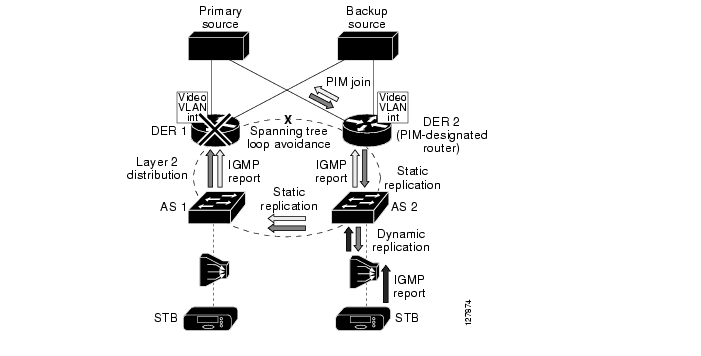
A network design that aggregates multicast video traffic at Layer 2 results in a complex multicast configuration, as well as in significant inefficiencies in multicast traffic behavior. Figure 3-3 illustrates the configuration complexity and transport inefficiencies when a Layer 2 distribution network is used for multicast video.
Figure 3-3 Multicast Traffic Flow with Layer 2 Distribution
When multicast video is aggregated at Layer 2, the resulting design typically uses more than one DER for redundancy. As a result, the PIM protocol state machine elects a designated router (DR). The DR is responsible for registering sources and sending upstream join and prunes on behalf of the members of the subnet (VLAN). In addition, the network selects an IGMP querier for the served subnet. The IGMP querier is responsible for sending IGMP queries on the subnet served by the redundant IP edge routers.
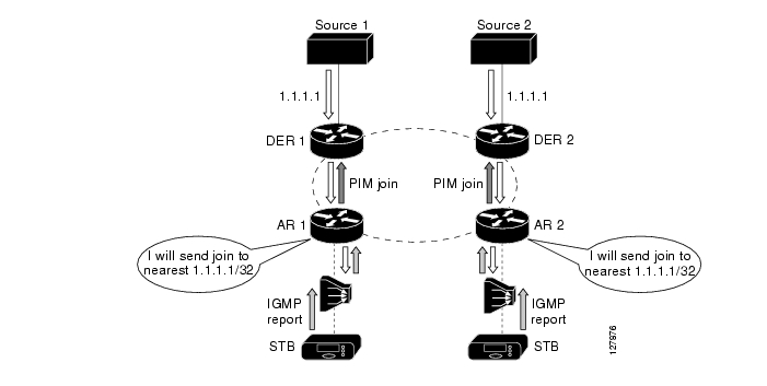
Each aggregation switch (AS) is responsible for replicating multicast streams from the distribution network to aggregation ports that have subscribers joined to them. As shown in Figure 3-3, there are two potential sources inserting video into the distribution network. These are DER 1 and DER 2. Because either of these two sources may be used to send multicast traffic onto the ring, each aggregation switch must send IGMP joins up both of the uplinks. This IGMP behavior makes it very difficult for the Layer 2 switches to determine when and when not to replicate multicast traffic on the distribution ring. To make multicast work properly in this type of environment, each port on each switch must be configured to replicate packets dynamically by using IGMP or statically. Ports that are configured to replicate dynamically send the traffic associated with a multicast group only if there has been an IGMP join issued for that multicast group. Ports that are configured to replicate statically send all multicast traffic all the time, independently of whether an IGMP join has been issued. In the case of Figure 3-3, each upstream port on each switch must be configured for static replication, because the downstream multicast traffic could potentially flow from either direction on the ring. This configuration results in additional complexity when multicast is configured on redundant topologies.
In addition to being more complex to configure in a redundant topology, multicast is less efficient. This is because multicast streams must be sent everywhere in the Layer 2 ring, independently of where an IGMP join was issued. Figure 3-3 illustrates an example multicast replication in a Layer 2 environment. Here the subscriber has issued a channel-change request from the STB attached to AR 2. The channel-change request results in an IGMP join message being propagated in both directions of the distribution network to both DER 1 and DER 2. DER 2 has been elected as the designated router, so it translates the IGMP join into a PIM join, while DER 1 ignores the IGMP join request. As a result of the IGMP join, DER 2 sends the multicast stream to the ring. Because AS 2 is using IGMP snooping on the downstream link, it is the only switch that replicates the stream to the DSLAM. Note, however, that the multicast traffic gets propagated all the way through the Layer 2 ring to DER 1. Each switch must replicate the traffic to other switches on the ring, because it is very difficult to determine where to send the multicast traffic on the ring based on IGMP snooping alone. DER 1 drops the multicast traffic when it receives it, because it does not have any "downstream" requestors for the stream. The result of using Layer 2 in the distribution network is that bandwidth is wasted on the distribution ring, because the multicast stream must be sent everywhere—independently of which nodes on the ring have asked for the traffic.
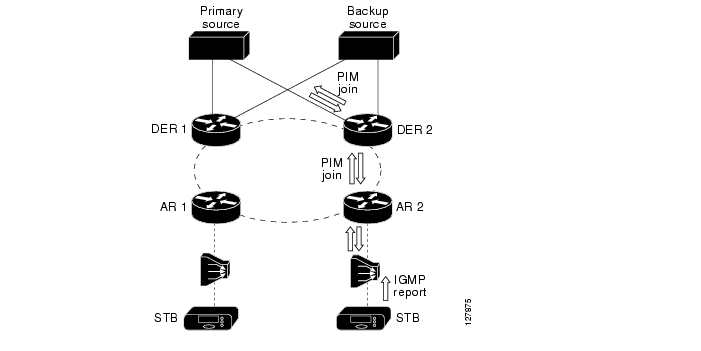
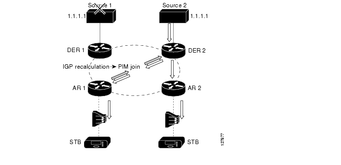
Figure 3-4 illustrates multicast operation and traffic flow when a Layer 3 distribution network is used for video. Here all nodes in the redundant topology are in the same Layer 3 topology. This results in simpler configuration as well as a more efficient traffic flow pattern. IP multicast is inherently different from Layer 2 forms of replication, because the multicast tree is build from PIM messages that are routed from the edge of the IP network to the source by means of reverse-path routing. Reverse-path routing is essentially the same as destination-based routing, except that the path to the source is looked up on the basis of the IP source address. This figure illustrates how the PIM messages are routed to the source and how the multicast distribution tree is built more efficiently as a result.
Figure 3-4 Multicast Traffic Flow with Layer 3 Distribution
In this figure, the subscriber has again issued a channel-change request from the STB attached to AR 2. The request results in an IGMP join message being sent to DER 2. Release 1.0 uses Source Specific Multicast (SSM), along with SSM mapping, as the IP multicast technology for the broadcast video service. As a result, AR 2 can translate the IGMP join request into the IP address of the encoder that is being used to generate that stream. With the IP source address, AR 2 uses reverse-path routing to decide where to send an PIM message. In this case, the shortest path to the primary source is through DER 2.
Once PIM state is established, DER 2 replicates the multicast stream to AR 2, which in turn sends the multicast stream to the DSLAM and the STB. Note that the multicast stream is not replicated throughout the distribution ring as it was in the Layer 2 scenario. This is because reverse-path route lookup results in a multicast tree that is built from the source directly to the nodes that requested the traffic. The result of using Layer 3 in the distribution network is an IP multicast environment that is simpler to configuration and more efficient in bandwidth use than are Layer 2 environments.
AR-Based Layer 3 Edge
When the AR is configured as the Layer 3 edge for video, the network is typically configured so that the AR is located at a different point in the network than the Layer 3 edge for Internet access services. This type of configuration may be considered not as architecturally "clean" as having the Layer 3 edge for all services located at the same point in the network. However, as described below, these issues are far outweighed by the benefits of using a Layer 3 distribution network for video services. Release 1.0 uses an AR-based Layer 3 edge to take advantage of these benefits.
Note that the AR may not be the node that directly aggregates the GE uplinks from DSLAMs. The AR is defined as the first node in the physical topology that aggregates enough subscribers that either path or node redundancy is required for video services. In a ring topology, the AR is defined as the node that connects the ring to a nonredundant hub-and-spoke aggregation architecture. In a hub-and-spoke topology, the AR is defined as the first node that includes redundant uplinks to the distribution network. In topologies where the AR does not terminate the GE uplinks from DSLAMs, there may be a Layer 2 aggregation network between the DSLAMs and the AR that does not include either path or node redundancy. Layer 2 Aggregation Alternatives, provides details on Layer 2 aggregation schemes that may be used between DSLAMs and the AR.
The sections below provide details on some of the benefits that make the AR the best choice as the Layer 3 edge in a video topology.
Benefit: Source-Specific Multicast
When the AR is configured as the Layer 3 edge for video services, the distribution network can take advantage of IP multicast features such as Source Specific Multicast (SSM). SSM is a technology that enables the network to build a separate distribution tree for each multicast source. SSM simplifies the operational complexity of configuring a multicast network, because it does not require the configuration of a rendezvous point (RP) to allow multicast forwarding as non-source-specific multicast technologies do. In addition, SSM only creates a multicast distribution tree to a specific multicast source address. SSM is considered more secure than non-source-specific multicast, because the multicast client must know both the multicast destination address and the multicast source address in order to join the multicast group. To create a source-specific multicast tree, SSM relies on IGMPv3 signaling from multicast hosts. IGMPv3 includes the multicast source address in the multicast join request. Because current-generation STBs do not support IGMPv3 signaling, the AR can be configured to map IGMPv2 requests received from the aggregation network to PIM SSM (S, G) (source, group) messages in the distribution network. This translation process maps the multicast destination address specified by the STBs in IGMP messages to a combination of multicast source and destination addresses in PIM messages. Release 1.0 of the solution uses SSM mapping at the AR to provide SSM support for STBs that do not support IGMPv3.
Benefit: Anycast Support
When the AR is configured as the Layer 3 edge for video, the distribution network can take advantage of "anycast" support for either the load balancing or the fast failover of video encoders. IP multicast technology natively supports the ability for "anycasting" of IP multicast sources. With anycasting, one configures two or more multicast sources that are sending to the same IP multicast group (with the same multicast destination address) and have the same IP source address. When used with PIM sparse mode, IP multicast technology uses a reverse path lookup to determine which IP source is closest to any particular PIM edge node. The result is that the replication path for a single multicast group can consist of a separate multicast tree for each broadcast encoder. Figure 3-5 illustrates the use of anycasting for load sharing between multiple video encoders.
Figure 3-5 Anycast-Based Load Sharing between Video Encoders
Note that the ability to instantiate multiple multicast replication trees for the same multicast destination is not possible when Layer 2 switching is used. Because each node in a Layer 2 network simply uses IGMP snooping to determine when to replicate packets, anycasting in a Layer 2 domain would result in having the stream from each multicast source replicated to all multicast destinations. Because of this, anycasting is applicable only within the context of a Layer 3 switching environment.
Benefit: Fast Failover of Video Encoders
In addition to supporting load sharing among multicast sources, anycasting can be used to support the fast failover of video encoders. When anycasting technology is combined with the ability of the network to detect the failure of an encoder, routing protocols reconverge. This reconvergence results in the reverse path from the ARs to the DER being recalculated to take into account that the location of the multicast source that has been changed. The IP reconvergence then triggers PIM to resend a join request along the path to the new multicast source. Figure 3-6 illustrates the use of anycast technology to implement the fast failover of redundant video broadcast sources. Release 1.0 used this technology to implement fast failover between redundant broadcast encoders.
Figure 3-6 Fast Multicast Source Failover Using Anycast
Benefit: Asymmetric Networking
Finally, when the AR is configured as the Layer 3 edge for video, the distribution network can be configured to support asymmetric bandwidth for video services in the distribution network. The traffic pattern associated with broadcast video and VoD services is extremely asymmetric. Each video channel or session requires multiple megabits of bandwidth in the downstream direction, while the upstream traffic is limited to control signaling for the service. Asymmetric networking allows the network to be configured for more bandwidth in the downstream direction than in the upstream direction. This reduces the cost of the transport network, because it allows the network provider to take advantage of optical components such as wavelength division multiplexing (WDM) transponders and other optical equipment that can be deployed in a unidirectional manner.
Video Forwarding Architecture
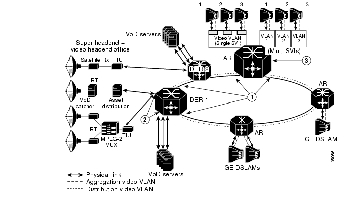
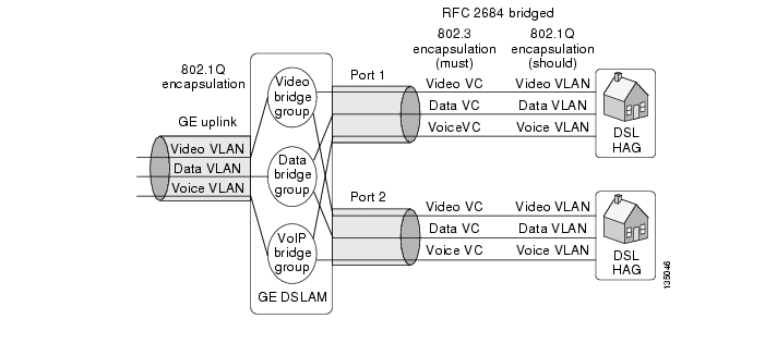
Once the choice is made to position the Layer 3 edge for video at the AR, the aggregation/distribution forwarding configuration becomes fairly straightforward. The service-separation architecture used in the solution results in the GE link from each DSLAM being configured for three separate 802.1Q VLANs to aggregate Internet access, voice, and video services. Figure 3-7 illustrates the overall video forwarding architecture discussed in this section.
Figure 3-7 Video Forwarding Architecture
AR Configuration
The AR has a set of interfaces connecting to the distribution network and a set of aggregation interfaces connecting to DSLAMs. The AR is configured to switch packets between the distribution and aggregation interfaces at Layer 3. Separate VLANs are configured for each service on each of these interfaces.
Each upstream port connected to the distribution network is configured to use 802.1q encapsulation (VLAN trunking) and contains three separate Layer 2 VLANs for the Internet access, voice, and video services. The Layer 2 video VLAN of each upstream port is terminated in a separate Layer 3 switched virtual interface (SVI). This configuration causes video coming in on any physical port to be switched at Layer 3 to any other physical port.
Note
There are two alternative configurations for the downstream aggregation ports: single SVI and multiple SVI configurations. In the single-SVI configuration, a single video SVI is configured for all of the GE ports connected to the DSLAMs. In the multiple SVI configuration, a separate video SVI is configured for each of the downstream GE ports connected to the DSLAMs. Each of these two configuration options has benefits and drawbacks. The configuration option that is chosen for a particular network design depends on the benefits that the service provider finds most important in the network.
Single SVI Configuration
The single SVI configuration is the simpler of the two models to configure and maintain. With this model, there is a single IP interface and as a result a single DHCP address pool to maintain for all subscribers served by the AR. This model is also simpler in that the VLAN ID for each service can be shared across all of the DSLAMs connected to the AR.
The down side to this configuration is the potential security risk associated with Layer 2 flooding across the downstream GE interfaces. The standard bridge-learning algorithm used in Layer 2 switches floods Ethernet frames if the MAC-layer forwarding engine does not have an entry for the destination MAC address in the packet or if the destination MAC address is a broadcast address. A malicious subscriber could potentially use this flooding behavior to learn about other subscribers by snooping packets that are flooded as part of standard bridge-learning behavior. This attribute of bridge learning is often not an issue for video, because the only upstream traffic coming from other subscribers on the video VLAN is requests for on-demand content. If a service provider considers the flooding behavior associated with bridge learning to be a significant security risk, then the multiple SVI configuration option described Multiple SVI Configuration, should be used.
With the single SVI configuration, the AR is configured to terminate the video LANs from the GE ports of the DSLAMs it aggregates into a single SVI. This results in the video VLANs from each of the GE links being switched at Layer 2 into a single Layer 3 VLAN interface on the AR.
The use of Layer 2 switching for this aggregation causes a complication for video that is dealt with in this solution. That complication is the potential flooding of VoD streams on downstream links because of issues with common learning-bridge algorithms.
Layer 2 switches that implement transparent LAN services use a learning-bridge algorithm that floods incoming unicast traffic to a particular MAC destination until a packet is received from that destination. This behavior normally is not an issue for most applications, because the MAC forwarding table is typically populated when ARP requests are sent between the routers or IP hosts attached to that LAN segment. An additional property of LAN switches is that they time out MAC table forwarding entries periodically to ensure that these entries do not become stale. This again is not an issue for most applications, because the client/server behavior of most applications means that the MAC forwarding table is repopulated when a client/server transaction occurs.
However, VoD applications do not exhibit this type of client/server behavior. While a VoD stream is being played, the traffic pattern is such that packets are being sent only from the video server to the subscriber. A separate stream-control session is used between the subscriber and the VoD server to support the ability to pause, fast forward, or rewind the video that the subscriber is playing. If the subscriber is simply playing the video, the only traffic sent on the control channel is periodic keepalives. This behavior of VoD applications can result in a learning bridge getting into a state where a MAC forwarding entry is aged and not replaced for a long period of time. The result is that the VoD stream is flooded to all downstream ports—with the ultimate result being that the video queue on downstream links such as DSL links become congested, causing all subscribers to experience poor video quality.
The solution deals with this issue by enabling unicast flood blocking on the video VLAN of the GE interfaces connected to the DSLAMs. This feature prevents the LAN switch from flooding unicast traffic when there is no bridge table entry for a destination MAC address. In addition, the Layer 3 video interface is configured to set ARP timeouts shorter than the MAC table aging timeout value. This configuration ensures that the router sends an ARP request to the downstream host before the MAC table entry times out. The resulting ARP request and response ensure that the MAC table entry gets repopulated before it is timed out.
Multiple SVI Configuration
The multiple SVI configuration is more complex to maintain than the single SVI configuration, because it requires a separate Dynamic Host Configuration Protocol (DHCP) address pool for each DSLAM connected to the AR. However, the multiple SVI configuration is considered more secure than the single SVI configuration, because there is no issue with Layer 2 flooding among downstream GE ports.
Note
In the multiple SVI configuration, a separate video SVI is associated with the video VLAN of each downstream GE port. Each SVI is configured with a separate IP subnet, so each SVI is associated with a separate DHCP address pool.
Note
DER Configuration
The downstream ports of the DER are configured identically to the upstream ports of the AR. (Refer to Figure 3-7.) The video stream is terminated in an SVI just as it is on the AR. One difference between the AR and DER is that the different services may be aggregated by different DERs. This allows the different services to be aggregated at different sites if necessary.
In the solution, video components such as video servers and real-time encoders are connected to redundant DERs. A load-sharing scheme provides video redundancy. This means that the VoD servers and broadcast video encoders connected to each of these routers are actively sending video during normal operation. Ports connecting video components to a DER may be configured at either physical Layer 3 switched ports or Layer 2 ports terminated in an SVI. To simplify address management, ports connecting VoD servers and real-time encoders may all be configured to be in the same Layer 2 VLAN, which is terminated in a single SVI.
IP Routing
To enable dynamic routing specific to video, a routing process is configured on the ARs and DERs. This routing process is configured only on the video SVI interfaces. This enables the video topology to converge at Layer 3 independently of the topologies for the voice and Internet access services. In Release 1.0, OSPF is the routing protocol for video.
Layer 2 Aggregation Alternatives
While the AR may be directly connected to the GE uplinks of the DSLAMs it aggregates, there may be network topologies with insufficient subscriber density to warrant having DSLAMs directly connected to an aggregation router. In these types of topologies, there may be a Layer 2 aggregation network between the DSLAM and the AR.
Note
The solution transport architecture specifies that the AR is where the Layer 3 edge for video should be. The transport architecture also specifies that the AR is defined as the first node in the physical topology that aggregates enough subscribers to require either path or node redundancy for video services. Given these transport requirements, it is important that the Layer 2 aggregation network between DSLAMs and the AR does not include either path or node redundancy. One way to identify such an aggregation network is that it does not require spanning tree algorithms to be configured in order to avoid bridging loops.
When a Layer 2 aggregation network is used between DSLAMs and the AR, it is also important that the number of subscribers aggregated at a single AR not cause forwarding table or ARP table scalability issues for the AR. (See Issue: Scaling for the Layer 2 MAC Table and Layer 3 Forwarding Table, for some of the issues associated with forwarding and ARP table scalability.) A general rule that can be used in network design to avoid scalability issues in the AR is that no more than 30,000 subscribers should be aggregated in a single AR.
The Layer 2 aggregation design described in this section prevents security issues in the DSL aggregation network that are associated with the flooding used in standard bridge-learning algorithms. To simplify the requirements of the aggregation switches, this design assumes that the switches support only standard bridge-learning algorithms, and do not support controlled flooding algorithms that prevent upstream packets from being flooded on down stream links. This design also assumes that aggregation switches are capable of segregating MAC broadcast domains through 802.1q VLAN tagging.
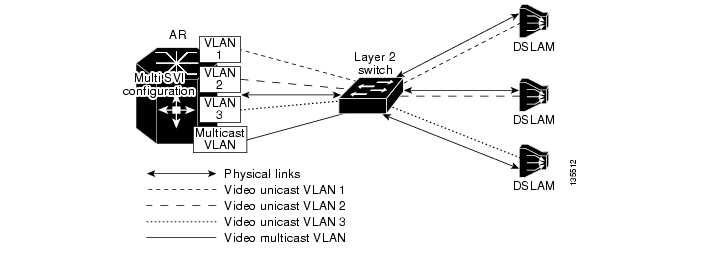
Under the above design assumptions, the Layer 2 aggregation design uses a separate VLAN ID per service per DSLAM. The use of a separate VLAN ID per service per DSLAM means that all MAC layer flooding on the aggregation switch is constrained to a single DSLAM per service. This prevents the security issues associated with MAC layer flooding, but it also means that separate copies of video broadcast channels must be sent to each VLAN—resulting in bandwidth being wasted on the link between the aggregation switch and aggregation router. To prevent multiple copies of video being sent on the link between the aggregation switch and the aggregation router, the Layer 2 aggregation design uses a separate multicast VLAN on which all multicast video traffic is sent. The multicast VLAN carries all broadcast video traffic between the aggregation router and the aggregation switch. The use of a separate multicast VLAN means that the aggregation switch that supports Layer 2 aggregation must be capable of performing IGMP snooping and replication between the single upstream multicast VLAN and the video VLAN on each downstream link. Cisco switches support a feature called Multicast VLAN Registration (MVR) to implement this function.
When the aggregation router is configured to use a Layer 2 aggregation network, the multi-SVI configuration described in AR Configuration, for the downstream aggregation links must be used. In addition to this SVI configuration, the AR must have one additional SVI configured for the multicast VLAN. This VLAN has the IP multicast features described in Multicast Configuration Options, configured on it.
Figure 3-8 illustrates aggregation at Layer 2.
Figure 3-8 Layer 2 Aggregation
Multicast
This section presents the following topics related to multicast:
•
•
•
Overview
A major component of the transport architecture is the multicast transport architecture for video. As stated previously, a Layer 3 forwarding architecture for video is used between the DER and the AR. The video topology is separated from the voice and Internet access topologies by means of a separate VLAN for video. This VLAN carries both unicast VoD streams as well as multicast broadcast-video streams.
PIM for multicast is enabled on the video VLAN interfaces on the DERs and ARs, along with OSPF. This enables a video-specific multicast topology to be built. PIM sparse mode is used for the broadcast video service.
The IGMP/PIM boundary for multicast occurs at the SVIs on the AR that are associated with the GE ports from the DSLAMs. IGMP joins are translated to PIM joins at the SVI. If the single SVI configuration described in Multicast Configuration Options, is used, then the GE ports from all of the DSLAMs are aggregated at Layer 2 in a single SVI. In this case, multicast replication must occur as part of the Layer 2 switching process.
Source Specific Multicast (SSM) is used in the Layer 3 network. SSM simplifies the operational complexity of configuring a multicast network, because it does not require the configuration of a rendezvous point (RP) to allow multicast forwarding as non-source-specific multicast technologies do. In addition, SSM only creates a multicast distribution tree to a specific multicast source address. SSM is considered more secure than non-source-specific multicast, because the multicast client must know not only the multicast destination address, but also the multicast source address, in order to join the multicast group.
Because SSM builds multicast replication trees that are specific to the IP address of the multicast source, there is an implicit requirement that all multicast join requests (IGMP/PIM joins) must include the address (or addresses) of the multicast source (or sources) in the request. While video STB applications could learn both the multicast source and destination address for each broadcast video channel through the electronic program guide (EPG), current-generation applications receive only the multicast destination address from the EPG. As a result, these applications send IGMPv2 join requests that contain only the destination multicast address in the request. The solution works around this by translating IGMPv2 requests that contain only the destination multicast address into SSM PIM join requests that contain both the multicast source and destination address at the AR. The ability to map the multicast destination address contained in IGMPv2 requests to a source/destination pair is called SSM mapping. To map between multicast destination addresses and source/destination pairs, SSM mapping can be configured to use either statically configured maps on each AR, or the services of a Domain Name System (DNS) server that contains a single map for all ARs. The solution uses the DNS-based approach to simplify the administration of this map.
Figure 3-9 (similar to Figure 3-7) illustrates the multicast features used in the solution with the aggregation and distribution networks.
Multicast Admission Control
The Release 1.0 architectural design does support the ability to perform a network-based connection admission control (CAC) function for the broadcast video service. In some broadcast video deployments, it may not be reasonable to support the transmission of all of the broadcast channels offered by the video service on the links between the AR and DSLAMs at the same time. For example, a broadcast video service may offer 150 standard-definition channels and 20 channels of high-definition television. If the channels are encoded by means of MPEG-2, the bandwidth required to support the transmission of all channels simultaneously is 862 Mbps. To ensure that there is no congestion in the queue used for the broadcast video service, bandwidth must be reserved on the GE aggregation links to the DSLAMs. This can be done by simply subtracting the bandwidth used for broadcast video from the bandwidth pools used by the application components of the other services (such as voice and VoD) that require guaranteed bandwidth. In the example above, if the amount of bandwidth that was reserved for broadcast video was based on supporting all channels simultaneously, only 138 Mbps of bandwidth would be available for voice and VoD. This is not enough bandwidth to implement a reasonable VoD service.
The amount of bandwidth reserved for broadcast video can by controlled by implementing an admission control function for that service. This can be implemented by limiting the number of broadcast streams that are replicated on a particular link. Because the GE aggregation links between the AR and the DSLAM are typically the most likely links to be oversubscribed, they are the best place to enforce a stream limit. When stream limits are used for broadcast video, there is a probability that an IGMP join sent by the broadcast video client application as a result of a channel-change request will fail. Because IGMP signaling has no acknowledgement associated with it, there is no explicit failure indication associated with a failed IGMP join request. Instead, a failed IGMP join request simply results in the requested MPEG stream not being delivered to the STB. The subscriber sees a blank picture as the result of a failed channel-change request. While this user interface is nonoptimal, it is consistent with what video subscribers currently experience when a broadcast channel is not available for some reason.
Figure 3-9 Multicast Forwarding Architecture
When a CAC function is used for broadcast video, it is important that the service provider sets the stream limit high enough that subscribers very seldom experience failures as a result of a channel-change request. This can be done by using statistical analysis methods such as Erlang analysis. The statistical analysis described in Static IP Multicast Joins on the AR, is an example of the type of analysis that can be used to determine what the stream limit should be set to in order to ensure a low blocking factor for a group of broadcast channels.
When the ip igmp limit command is configured on an AR, that router can enforce a maximum broadcast-bandwidth limit by limiting the number of IGMP joins on the ranges of multicast addresses associated with broadcast video to a configured maximum on the aggregation links that the router controls. The mapping of video channels to multicast addresses can be done in such a way that the AR can associate the bandwidth for different classes of video (standard definition, high definition, and so on) with different ranges of multicast addresses. IGMP join limits can then be set for each range of multicast addresses. For example, a service provider may choose to exclude some video channels from the video CAC function and instead reserve bandwidth for all of the channels that are excluded from that function. This configuration may be useful for managing popular channels that the service provider wants to ensure are never blocked. These channels can be excluded from the CAC function by simply not associating an IGMP limit with their multicast addresses.
Caution
Effect of Multicast on Channel-Change Performance
One of the important aspects of a broadcast video service that this solution characterizes is the effect of multicast join and leave latency on channel-change performance. This section documents the multicast configurations that testing has evaluated, and makes recommendations that achieve the following design goals:
•
•
•
Table 3-3 illustrates the major components of channel-change latency. Note that the largest factor in the channel-change delay is the I-frame delay associated with the video decoder. (The I-frame is a keyframe used in MPEG video compression.) As the table indicates, multicast performance should not have a significant effect on channel-change delay.
Table 3-3 Major Components of Channel-Change Latency
Multicast leave for old channel
50
Delay for multicast stream to stop
150 1
Multicast join for new channel
50-200
Jitter buffer fill
200
Conditional access delay2
0-2000
I-frame delay
500-1000
1 Assumes that the DSLAM implements IGMP fast-leave processing.
2 The conditional access delay is applicable to broadcast channels that are encrypted by means of a conditional access system (CAS) that modifies decryption keys periodically and carries updated decryption keys in-band in the video stream. The STB must wait for the latest set of decryption keys to be delivered in the video stream before it can perform any decoding. The amount of time associated with this delay depends on how often the CAS sends updated decryption information in the video stream.
Analysis of Multicast Bandwidth vs. Delay
The best approach to use for an IGMP/multicast configuration is based on a tradeoff between bandwidth and delay. IP multicast natively supports the ability to perform replication on a stream only when that stream is requested by a downstream device. While IP multicast and IGMP natively support dynamic replication, each can be configured always to replicate multicast data for a particular channel or channel group to any node in the network. When a channel or channel group is always replicated from the source to a particular node, that node is said to be configured for static joins of the channel or channel group. The benefit of configuring static joins at a particular node is that no channel-change latency is associated with dynamic signaling and replication from the source to the node on which static joins are configured. The down side of configuring static joins at a node is that the video streams for the channels that are statically joined are always sent whether a subscriber is watching them or not.
Statistical analysis can be used to determine when the benefits of static joins (less channel-change latency) outweigh the costs (additional bandwidth usage). This section describes the statistical analysis that was done as part of the solution to determine the recommendations for where in the network static joins should and should not be configured.
The behavior of a population of subscribers can be modeled statistically to determine, for a population of subscribers, the probability of at least one subscriber in the group being tuned to a set of television channels. If the probability of at least one subscriber being tuned to each of the channels in a broadcast channel group is fairly high, then the amount of bandwidth that is saved by performing dynamic joins on that group of channels is statistically insignificant. When statistical analysis shows insignificant bandwidth savings for a group of channels, static joins can be used on those channels without having a significant impact on the amount of bandwidth on the GE aggregation links.
The factors used in this analysis included the following:
•
•
•
The number of video subscribers served by a particular node depends on where that node is located in the network. Based on common expected video service take rates, the number of subscribers served by a DSLAM is typically about 500 while the number of subscribers served by an AR is typically about 5000.
The following is a statistical analysis model that is helpful in determining when to use dynamic joins, and when to use static joins.
Analysis of Dynamic Joins in a Video over IP Environment
Each subscriber is modeled as a random process selecting a channel to watch according to a given probability distribution across all possible channels. Given a group of channels, we would like to calculate the average number of channels in use, given the "popularity" probabilities of the channels. Because we are interested in determining the average number of channels in use, we can consider the channels to be probabilistically independent of each other and consider the channels one at a time.
For a single channel, the probability that this channel is idle is calculated as follows:
Let
p = P{a subscriber tunes to this channel}, and
N = number of subscribers subtended by the given AR or DSLAM
so that
P{channel is idle} = (1-p)N
For multiple channels, we sum the above expression.
Let
C = number of channels, and
pk = P{a subscriber tunes to kth channel}
so that the average number of channels in use, CIU, is
Channel-Change Latency Probabilities
When subscribers change channels, if they change to a channel that is not part of a static join and that no one else is watching, they experience some latency while the dynamic join is established before they can view the channel's content.
We assume that when there is a channel-change event, the probability a particular channel is changed to is proportional to that channel's popularity. This assumption can be combined with the above calculated P{channel is idle} and the knowledge of which channels are associated with static or dynamic joins to determine the probability that a given channel change results in the latency associated with establishing a dynamic join.
Let
D = the set of all channels involved in dynamic joins, and
PL = P{a channel change experiences latency due to a newly created dynamic join}
so that
Analysis
Given a set of channels with probabilities pk, they can be ranked from highest to lowest pk. Then, once they are ranked, we can have a cutoff value so that channels with higher pk get a static join and those with lower pk get a dynamic join. The questions then are, for a given cutoff,
•
•
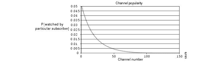
As an example, consider a 150-channel system with an exponential decay function for
P{subscriber tunes to kth channel}
Figure 3-10 graphs the channel popularity for this example.
Figure 3-10 Channel Popularity for a 150-Channel System
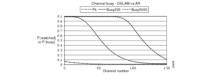
Figure 3-11 add curves showing the probability that a given channel is busy for subscriber bases of 200 (at a DSLAM) or 5000 (at an AR).
Figure 3-11 Probability a Given Channel is Busy for Subscriber Bases of 200 (at a DSLAM) or 50000 (at an AR)
The important thing to note here is that the P{busy} curve shifts dramatically to the right when the number of subscribers is increased from 200 to 5000.
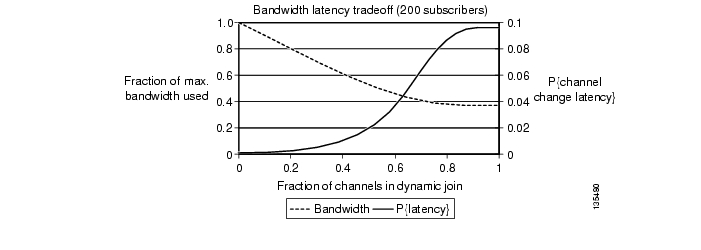
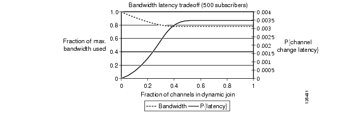
Figure 3-12 and Figure 3-13 show the tradeoff between average bandwidth requirements and channel-change latency probability for a DSLAM and an AR, respectively. The horizontal axis is the fraction of channels moved from a static join to a dynamic join. The two curves show the bandwidth required (as a percentage of bandwidth required in the static join case) and the probability of channel-change latency. (The two curves in each figure are shown on different scales to make them both visible.)
Figure 3-12 Tradeoff Between Average Bandwidth Requirements and Channel-Change Latency Probability for a DSLAM (200 Subscribers)
Figure 3-13 Tradeoff Between Average Bandwidth Requirements and Channel-Change Latency Probability for an AR (5000 Subscribers)
Figure 3-12 shows the tradeoff for the DSLAM (200 subscribers). There seems to be substantial opportunity in using dynamic joins where about half the bandwidth can be saved with a channel-change latency probability of about 1 in 50 (0.02). (See the vertical black line in the graph.)
Figure 3-13 shows the tradeoff for the AR (5000 subscribers). In this case, the best possible bandwidth savings is about 20%, even with all channels in dynamic joins. Here the channel-change latency probability is uniformly low, with a maximum value of about 1 in 300.
From the statistical analysis results described above, you can see that there is a typically a significant bandwidth savings to be gained (~60%) by using dynamic joins at the DSLAM. Because of this, we recommend that the multicast configuration models used on the links between the AR and the DSLAM take advantage of the dynamic replication capabilities native to IP multicast. Also from these results, it can be seen that the benefit of using dynamic vs. static joins at the AR depends heavily on the popularity of a channel or channel group. It may be best to join popular channels statically, and join less-popular channels dynamically. Static IP Multicast Joins on the AR, describes additional analysis that was performed to determine when it is best to perform static vs. dynamic joins of a channel group on the AR.
Multicast Configuration Options
From the above analysis, the solution architecture assumes that multicast traffic is replicated by means of dynamic Internet Group Management Protocol (IGMP) signaling on the GE aggregation links between ARs and DSLAMs, and also on the DSL access links between the DSLAM and HAG. The following sections detail the multicast configuration options included in the solution.
IGMP-Based Replication in the DSLAM
Because the DSLAM performs packet switching at Layer 2, it must use a Layer 2 method of implementing multicast replication based on dynamic signaling. In the transport architecture, the DSLAM performs multicast replication by means of IGMP snooping. A Layer 2 switching node that implements IGMP snooping uses the IGMP state machine to determine when to perform multicast replication to a particular link.
IGMP Snooping vs. IGMP Proxy Functionality
Note that the recommendation for the transport architecture is to use IGMP snooping and not an IGMP proxy function. IGMP snooping is defined as a function whereby the DSLAM uses IGMP messages and the associated IGMP state machine to determine when to perform replication of an incoming multicast stream on outgoing DSL lines. When IGMP snooping is used, the DSLAM appears totally transparent to the IGMP signaling path. It does not modify IGMP messages in either the upstream or downstream directions. With an IGMP proxy function, the DSLAM acts as an IGMP server to video STBs and as an IGMP client to upstream routers. With an IGMP proxy function, the DSLAM can statically join multicast streams coming from the AR and replicate them on demand, based on IGMP messages coming from the STBs.
IGMP proxy functionality is not recommended on the DSLAM for a couple of reasons. First, the IGMP proxy function complicates both the operation and configuration of IGMP signaling. This is because the signaling path is now split into two separate IGMP sessions between the STB and the AR. Second, the main benefit of an IGMP proxy function is to allow the DSLAM to join multicast groups statically from the AR and perform dynamic replication to the DSL line. As shown from the analysis in Analysis of Multicast Bandwidth vs. Delay, the benefits of statically joining broadcast channels at the DSLAM (decreased channel change latency) are far outweighed by the cost (additional bandwidth on the GE aggregation links).
Note
Cisco has load tested IGMP signaling on the Cisco 7600 series, for example, and no join or leave performance degradation was experienced with over 10,000 IGMP messages (join/leaves) per second. Thus, although the Release 1.0 multicast architecture does not require IGMP report suppression on the DSLAM, using this report suppression feature does not cause any issues with the multicast architecture.IGMP Fast Leave Processing
To meet the channel-change time requirements, the DSLAM must perform IGMP snooping with fast leave processing. Fast leave processing is a modification of the normal IGMP Version 2 host state machine. In IGMPv2, when a router (IGMP server) receives an IGMP leave request from a host (IGMP client), it must first send an IGMP group-specific query to learn whether other hosts on the same multi-access network are still requesting to receive traffic. If after a specific time no host replies to the query, the router stops forwarding the traffic. This query process is required because, in IGMP Versions 1 and 2, IGMP membership reports are suppressed if the same report has already been sent by another host in the network. Therefore, it is impossible for the router to know reliably how many hosts on a multi-access network are requesting to receive traffic.
The requirement of making IGMP queries and waiting for a response can be removed if there is only a single video STB per DSL line that is making IGMP requests. In this case, when an STB sends an IGMP leave request, the DSLAM can safely and immediately stop sending the multicast stream down the DSL line from which the request came. The ability for a node that supports IGMP snooping to stop sending a multicast stream immediately on the receipt of an IGMPv2 leave request is called fast leave processing. The solution requires that DSLAMs support IGMP snooping with fast leave processing.
However, IGMP snooping with fast leave processing does not work when more than one STB is connected to a DSL line. The problem with fast leave processing is that if two STBs attached to the same DSL line are tuned to the same channel, the first STB that tunes off that channel causes the DSLAM to stop sending the multicast stream for that channel. This in turn causes the second STB to stop receiving video. The workaround for this problem requires additional functionality in both the STBs and the DSLAM. STBs must always send IGMPv2 join and leave requests during a channel-change operation, independently of whether other STBs on the same network segment are currently joined to the same multicast group. The DSLAM must keep track of the IP source address associated with each IGMP join and leave request. The DSLAM stops sending a multicast stream to a particular DSL line when all of the IGMP hosts (as specified by the IP source address in each IGMP message) have issued IGMP leave requests. (In fact, these modifications to the IGMPv2 state machine are required in order to make IGMP hosts compliant with IGMPv3.)
IGMP-Based Replication in the AR
To support dynamic replication to aggregation links, the AR is configured in one of two ways, depending on which configuration from AR Configuration, is used. If the AR is configured by means of the single SVI configuration described in Single SVI Configuration, it is configured to perform multicast replication at Layer 2 by means of IGMP snooping. If the AR is configured to use the multiple SVI configuration described in Multiple SVI Configuration, multicast replication is performed at the IGMP/PIM boundary. Both of these methods depend on the AR's ability to process IGMP messages in order to determine when to replicate multicast traffic to the GE aggregation links.
Because the AR potentially aggregates many subscribers, it must be capable of processing a high volume of IGMP join and leave requests if many subscribers are changing channels at the same time.
The solution testing effort characterized the performance of IGMP on the AR by flooding the AR with a constant rate of IGMP join and leave requests, in order to determine the effect on CPU performance in the AR, as well as on the network multicast join delay that contributes to the channel-change performance experienced by an STB. To determine that, an IGMP host makes an IGMP join request for a multicast address that is currently not being sent on the GE aggregation link while the AR is being flooded with IGMP join and leave requests for a different multicast address. The test measures the amount of time it takes from the time the join is sent until the time the stream is delivered, both when the AR is not busy and when it is under various IGMP load conditions.
Static IP Multicast Joins on the AR
If the AR is configured to use static IP multicast joins, all of the multicast streams that are configured with static joins are sent through the distribution network to the AR independently of whether or not IGMP requests have been made by STBs.
Statistical analysis can be used to determine when the use of static joins in the AR does not result in a significant amount of additional bandwidth on the GE aggregation links. The results of this statistical analysis are shown below.
Each service provider must decide, for each channel group, whether that channel group should be a static join or a dynamic join, based on a balance of configuration overhead vs. delay probabilities. Table 3-4 summarizes the factors and formulas used in this analysis.
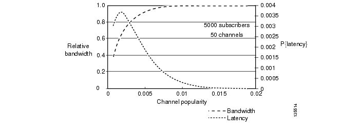
Figure 3-14 illustrates the results of the statistical analysis model for bandwidth/latency tradeoff at the AR. Here fixed values are used for the number of channels in a channel group (C = 50) and the number of subscribers served by the node (N = 5000). Note how bandwidth and latency vary with average channel popularity.
Figure 3-14 Bandwidth and Latency vs. Channel Popularity: 5000 Subscribers at the AR
Based on the above, we can make a general recommendation that channel groups with an average per-channel popularity of 0.05% or less should be joined dynamically at the AR, while channel groups with an average per-channel popularity of greater than 0.05% could be joined statically.
Note
IGMP Functionality in the STB
As described in Broadcast Client, the broadcast client in the video STB is responsible for implementing channel-change requests from a subscriber by issuing an IGMP leave followed by an IGMP join.
Because the bandwidth on the DSL line is often limited, the broadcast client on the STB typically implements the channel-change function by sending an IGMP leave, waiting for the video stream from the channel that is being tuned away to stop, and then an IGMP join. The broadcast client must support IGMPv2, because version 2 is the first release of IGMP that provides the ability for a client to signal explicitly when it wants to leave a multicast group. Broadcast clients that support IGMPv2 should also send IGMP joins during a channel change, independently of whether other STBs have also sent IGMP joins for the same channel.
Note
Broadcast clients should also support IGMPv3. In addition to IGMP state machine enhancements, the support of IGMPv3 by the broadcast client enables the client to specify one or more IP source addresses of broadcast encoders from which it wishes to receive the broadcast channel. To support this function, the electronic program guide (EPG) must be updated to send both the multicast group address as well as a list of the IP addresses of real-time encoders that may be used for each broadcast channel. When the broadcast client as well as the EPG are updated to support IGMPv3, the multicast solution is significantly simplified, because Source Specific Multicast (SSM) is supported from the STB all the way to the real-time encoder. As a result, there is no need to turn on SSM mapping in the AR.
Internet Access Forwarding
Because different services in the transport architecture use separate VLANs, the forwarding architecture for Internet access may be different from that for video. The Internet access forwarding architecture used in the solution provides an example of how Internet access can be implemented alongside a video service.
The solution uses Layer 2 forwarding in the aggregation and distribution networks for Internet access. An example Internet access service that could be implemented by this type of architecture would be PPPoE aggregation to a broadband remote-access server (BRAS) that is connected to the DER. Figure 3-15 illustrates the Layer 2 forwarding architecture used for the Internet access service.
To conserve MAC forwarding entries in both the ARs and DERs, a separate VLAN is used for Internet access for each AR. This configuration makes the VLAN topology look like a hub-and-spoke topology with a separate logical network between each AR and the two DERs. Spanning tree is configured to break the link between the DERs to avoid a forwarding loop. After the spanning tree converges, the VLAN topology looks like separate point-to-point connections between each AR and the DERs. This logical topology conserves MAC address forwarding entries on both the ARs and DERs, because each VLAN now connects only two physical ports. MAC learning algorithms are not needed when a logical topology consists of only two physical ports, because each MAC frame that arrives at one port is always sent on the other port.
Note
Figure 3-15 Configuration for Internet Access Forwarding
Voice Forwarding
Because the transport architecture uses separate VLANs for each service, the forwarding architecture for voice services may be different from that for video and Internet access. The voice forwarding architecture provides an example of how a voice service may be implemented alongside video and Internet access services.
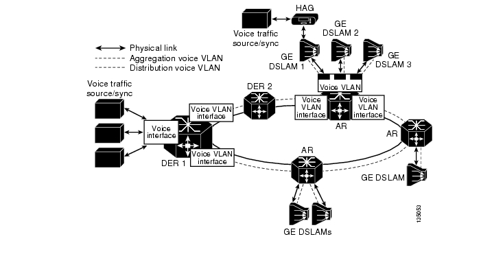
The transport configuration for the voice service uses a transport architecture similar to that for video. The AR is the Layer 3 edge for voice services. Voice packets are forwarded through the distribution network on a separate VLAN that is terminated in each AR and in the DERs. Voice traffic sources and syncs are attached to the DERs through separate physical or logical interfaces. A separate routing process is configured for voice and includes all of the voice interfaces on the ARs and DERs. Figure 3-16 illustrates the voice forwarding configuration used in Release 1.0.
Figure 3-16 Voice Forwarding Configuration
Management
Aspects of management include the separation of services, the management of address spaces, element and network management systems, and service monitoring. These topics are addressed below:
•
Management Transport
The service separation architecture supported in this release of the solution provides the flexibility to allow service providers either to manage each service independently or use a common infrastructure for all services. The level of sharing among services can be controlled by configuring a subset of the IP address to be shared, and deploying common infrastructure components within the shared IP address space. A service provider could thereby share some components such as DHCP and DNS servers, while making other components such as VoD servers specific to the video service.
Solution testing included the configuration and testing of the scenarios where DNS and DHCP servers are shared across services. In Release 1.0, a separate management subnet is configured for components that may be shared across services such as DHCP and DNS servers as well as management hosts and as element management systems (EMS) and network management systems (NMS). These components are connected to the DER through either a separate physical port or a separate VLAN than are devices associated with video or voice services. The address spaces associated with different services such as voice and video are separated by configuring a separate routing process per service. The management subnetwork can be shared across services by including the interface associated with that subnetwork in the routing process associated with each service.
DHCP Configuration
To enable dynamic address allocation for the devices in the home, the network is configured to support Dynamic Host Configuration Protocol (DHCP). Because the AR is the Layer 3 edge device, DHCP relay functionality is configured on the downstream video VLAN interface of that router. The helper address used with DHCP relay points to a DHCP server located in the management network.
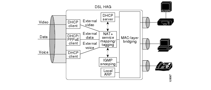
Release 1.0 supports a segmented address allocation scheme that uses a separate DHCP address pool per service. With segmented address allocation, the downstream voice and video SVIs on the AR are associated with separate DHCP address pools. In this environment, the home network is actually divided into three separate IP subnets, where each subnet is associated with a different service topology. The issue with this form of address assignment is that it results in a home network environment where devices within the home network that are associated with different services will be able to communicate with each other only by using a Layer 3 capable home access gateway. ( NAT/Layer 3 Functionality, describes an example of functionality that a HAG could implement to enable devices associated with different services to communicate with each other.)
In some environments, the service provider may choose to identify video subscribers by identifying the DSL port that connects the subscriber to the network. In these environments the DSLAM must be capable of snooping DHCP requests from devices in the home network and inserting a DSL port ID in the DHCP request by using DHCP option 82. The DHCP server can then extract this port ID from the DHCP request and use it to identify the subscriber. (DHCP option 82 is described in RFC 3046.)
Note that because the AR is acting as a DHCP relay agent, a DSLAM that supports DHCP option 82 must support the ability to appear as a trusted downstream (closer to client) network element (bridge) between the relay agent (AR) and the client (STB). In this mode, the DSLAM inserts DHCP option 82 information but does not set the "giaddr" field in the DHCP request. In addition, because the DSLAM is not acting as a DHCP relay agent, it does not modify the destination MAC address of the DHCP request, and just forwards it using Layer 2 forwarding.
Note
EMS/NMS
The solution does not yet include the integration of element management or network management systems into a video transport solution. The Cisco command line interface (CLI) is the method of configuring the Cisco platforms included in the solution.
Redundancy
The solution addresses fast recovery from the failure of video infrastructure components, as well as of network components in the distribution network, such as physical links or network switching components. Solution testing looked at the recovery associated with failures of video components such as the VoD servers used for on-demand services and the real-time encoders used for broadcast services.
Note
In addition, solution testing has determined how to optimize the network reconvergence time associated with the failures of links in the distribution network, as well as the failure of a DER.
This section discusses two types of redundancy:
•
Video-Infrastructure Component Redundancy
Figure 3-7 illustrates how the transport architecture supports the redundancy of video infrastructure components such as VoD servers and real-time encoders. The solution test bed included redundant video pumps and real-time encoders attached to redundant DERs.
The solution relies on application-layer failover between the redundant video pumps attached to the DERs in one or more video headends. The video server must support the ability to load-balance VoD sessions between the video pumps attached to the redundant DERs. In addition, a video server must be capable of detecting the failure of a video pump and routing new VoD requests from STBs to still-active video servers in the event of the failure of a video pump.
Solution testing has also characterized the recovery time associated with the failure of real-time encoders by using anycast services. As discussed in Benefit: Fast Failover of Video Encoders, anycast technology can be used to support the ability to detect and recover from the failure of a real-time encoder in the time it takes for the network to reconverge. Release 1.0 testing used redundant real-time encoders configured with the same IP source address attached to the redundant DERs to implement the failover of encoders by using anycast.
Testing simulated the signaling of an encoder (broadcast source) failure, which effectively removes the host route for the failed encoder from the DER. The multicast network between the DERs and the ARs then reconverge. The result is that all that the IP multicast trees for the affected broadcast channel consist of sources from the encoder that is still available.
Network Redundancy
The transport architecture uses dynamic IP routing in the distribution network. This means that the failure of either a physical link or a DER should cause both unicast and multicast routing in the IP transport network to reconverge.
Solution testing has characterized the average and maximum reconvergence times for both unicast and multicast in the event of a link failure or the failure of a DER in the distribution network. The reconvergence trigger events that have been characterized by testing include the following:
•
•
•
Average and worst-case reconvergence times were measured by measuring how long video streams are disrupted at the STB. Testing has also characterized the effect on video quality of the loss of IP video to the STB. During testing, the IP video stream was disrupted for different periods of time (50, 100, 200, 500, and 1000 msec) in order to determine quantitatively the effect of this on video quality. Using this reconvergence and video quality information, the service provider should be able to determine accurately the effect of various network outages in various locations in the video transport network.
Solution testing has also determined the optimal configuration for IP unicast and multicast parameters to optimize reconvergence time for video. Finally, testing has determined the ability of the Quality of Service configuration described in QoS Architecture to enable the service provider to degrade on-demand services without affecting video broadcast services in the event of a failure in the distribution network.
Note
Release 1.0 Configurations
Two physical distribution-network topologies based on the transport architecture described in Distribution and Aggregation Transport Architecture were tested. Both distribution topologies are based on GE rings between the video headend office and video switching offices.
This section presents the following topics:
•
•
•
Overview
One topology (referred to as Configuration 1) uses a 10-GE ring between the VHO and VSOs. This configuration uses symmetric bandwidth around the ring to provide physical link redundancy for all services.
The other topology uses asymmetric transport links between the VHOs and VSOs to provide a cost-reduced 1-GE transport solution that is optimized for video. This topology reduces the cost of the distribution network by combining bidirectional and unidirectional 1-GE links between the VHO and VSOs. This topology provides asymmetric bandwidth pipes that are optimized for the traffic pattern associated with video. It reduces cost in 1-GE deployments by eliminating bidirectional optics such as lasers when they are not needed. This topology provides physical link redundancy for the Internet access, voice, and broadcast video services, but it does not provide full redundancy for VoD services. In the event of a link failure, VoD services are degraded without affecting any of the other services through the use of the QoS architecture described in QoS Architecture.
Configuration 1: 10-GE Layer 3 Symmetric Ring
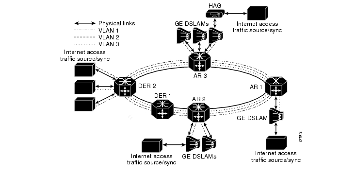
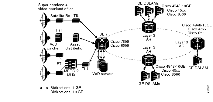
Figure 3-17 illustrates the 10-GE-based symmetric ring topology used in Release 1.0. This topology uses the aggregation/distribution transport architecture described in Distribution and Aggregation Transport Architecture, with the Layer 3 edge at the AR.
Figure 3-17 Configuration 1: 10-GE Symmetric Ring
Table 3-5 lists the transport components tested for Configuration 1.
The 10-GE topology shown in Figure 3-17 provides fiber redundancy for all services. A link cut anywhere on the ring results in traffic from all services being rerouted in the other direction around the ring. Solution testing includes a test scenario where the failure of a link in the 10-GE ring and the resulting rerouting of video traffic results in steady-state congestion of video traffic on the remaining 10-GE links. In this scenario, the QoS configuration described in QoS Architecture, causes the VoD flows to be affected, while not affecting the broadcast video service at all.
Configuration 2: N x 1-GE Asymmetric Ring
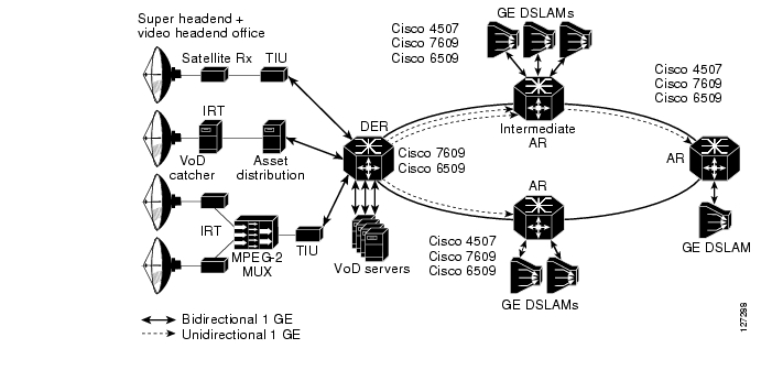
Figure 3-18 illustrates the N x 1-GE-based topology used in Release 1.0, where N represents any multiple of 1-GE rings. As in Configuration 1, this topology uses the aggregation/distribution transport architecture described in Distribution and Aggregation Transport Architecture, with the addition of unidirectional transport links between the DERs and the AR. Also as in Configuration 1, the Layer 3 edge is at the AR.
Figure 3-18 Configuration 2: N x 1-GE Asymmetric Ring
Table 3-5 lists the transport components tested for Configuration 2.
The 1-GE configuration could be used in networks where the amount of traffic in the distribution network does not initially support the deployment of 10-GE links. The transport architecture supports a "pay as you grow" model of deployment, where additional bandwidth could be deployed by adding 1-GE links in the ring as the amount of traffic grows. Because both VoD and broadcast video essentially generate traffic in only one direction, the asymmetric transport architecture allows bandwidth to be added for video in a more cost-effective manner than is provided by fully symmetric bandwidth. Video bandwidth can be added to the distribution network by deploying additional unidirectional 1-GE links between the DER and the ARs. The use of unidirectional links provides a significant savings in the transport network, because most of the cost associated with a DWDM GE interface (approximately 80 percent) is the cost of the transmit laser. The transmit laser may be integrated into the line card by means of pluggable DWDM optics, or it may be implemented externally from the line card by means of a DWDM transponder. The 1-GE line cards tested in this configuration support receive-only pluggable DWDM optics that can used on the receive side of a unidirectional link. In addition, Cisco supports unidirectional 1-GE DWDM transponders.
The topology illustrated in Figure 3-18 is implemented by means of a 1-GE bidirectional ring between the DER and the ARs. Additional unidirectional 1-GE links are then used from the DER to the first-hop ARs, to provide additional bandwidth for VoD. Unidirectional 1-GE links may also be used between ARs for this purpose as well.
Bidirectional Interface Support
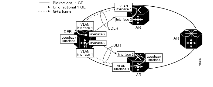
Some protocols that are required to support dynamic routing such as ARP, OSPF, and other routing protocols make an implicit assumption that they are running on bidirectional interfaces. When these protocols are enabled on an interface they respond to protocol requests on the same interface that the request was received on. Because the solution transport architecture is intended to support dynamic routing, it is important that the unidirectional links appear as if they are bidirectional to these protocols. Consequently, Unidirectional Link Routing (UDLR) is used on unidirectional interfaces to make them appear bidirectional at the interface layer. UDLR combines a unidirectional link with a GRE tunnel that is provisioned between the same two nodes that the unidirectional link runs between. Both the unidirectional link and the GRE tunnel are combined at the interface layer to make the unidirectional link appear to be bidirectional.
In Release 1.0, the upstream GRE tunnel is configured between loopback interfaces on the downstream and upstream routers. The tunnel is routed back to the upstream router through the bidirectional 1-GE port. OSPF cost metrics are configured on the downstream interface to direct upstream IP packets through the bidirectional IP interface, as opposed to the UDLR back-channel interface. This is needed because the UDLR back channel is process switched and will have very low throughput capabilities as a result.
Figure 3-19 illustrates how UDLR is configured on the unidirectional interfaces in the asymmetric Ethernet topology.
Figure 3-19 Interface Configuration for Bidirectional Interface Support
Routing Configurations
Note that the unidirectional links do not provide path redundancy around the ring. Because of this, if a unidirectional link fails, there will be no alternate path to carry the traffic on that link around the ring in the other direction. The unidirectional links provide cost-optimized transport for VoD traffic. Because of the relaxed availability requirements for VoD services, it may not be necessary to provide path redundancy on links used to carry VoD traffic. Note that this is typically not the case for other triple-play services that include Internet access, voice, and broadcast video. Because of this, it is important that packets associated with the Internet access and voice services be routed only to the bidirectional links that provide path redundancy, while packets associated with video services may be routed to either the bidirectional or unidirectional links.
As discussed previously, the availability requirements associated with broadcast video are typically more stringent than those for VoD. In the event of a link failure, the QoS architecture described in QoS Architecture, ensures that VoD packets are dropped before broadcast video packets are. While this QoS configuration should be sufficient to ensure that broadcast video and other services are unaffected in the event of a link failure, some providers may want to ensure that a failure that causes a disruption of the VoD service will not cause any degradation to the other services. This can be achieved by ensuring that VoD packets are routed only to unidirectional links, while broadcast video packets are routed only to bidirectional links.
Two routing configurations tested as part of the solution can be used as part of the asymmetric topology shown in Figure 3-18. These support broadcast and on-demand video routed together, as well as routed separately. Both configurations support Internet access and voice services (which are configured identically for both of the routing options). These two configurations implement the methods of routing the broadcast video and VoD services described above, and route Internet access and voice packets to the bidirectional links that provide path redundancy.
However, the two configurations differ in how they forward broadcast video and VoD packets. The first configuration routes broadcast video and VoD packets in the same logical topology, which uses both the bidirectional and unidirectional links of the asymmetric topology. The second configuration uses separate logical topologies for broadcast video and VoD. Broadcast video shares the same logical topology as voice in the distribution network and is routed only through the bidirectional links. On the other hand, VoD is carried in its own logical topology, which is routed only through the unidirectional links.
Broadcast and On-Demand Video Routed Together
In this configuration, both broadcast video and VoD traffic are carried in a single logical pipe through the distribution network. This logical pipe consists of a video SVI on the bidirectional GE links in the distribution network and a Layer 3 video interface on each unidirectional link. A video routing process (OSPF) is configured across the video SVIs on the bidirectional links as well as on Layer 3 video interfaces on the unidirectional links.
Because each of these interfaces is configured as a Layer 3 interface, CEF switching is used to switch packets among the interfaces. An implicit property of CEF switching is that it performs load balancing between IP interfaces when the CEF forwarding table shows the interfaces have the same cost to reach a particular destination. When IP interfaces are configured on two or more physical links between a pair of forwarding nodes and the interfaces are configured to have the same cost, all of the destinations reachable by these interfaces have the same cost in the CEF forwarding table. Because of this, all of the IP flows that are routed over the video interfaces configured on the unidirectional and bidirectional links are load balanced. On the AR and DER platforms supported in Release 1.0, the IP CEF load-balancing function is implemented as part of the hardware-accelerated forwarding function. The load-balancing function ensures that all packets associated with each flow are forwarded over the same link within the load-balanced group. The load-balancing function is implemented by feeding specific Layer 3 fields (IP Src, IP Dest) and Layer 4 headers (UDP/TCP src, UDP/TCP dest) of each packet into a polynomial hash function. The result of this hash is then used to select the interface through which the IP packet is sent.
Because of CEF load balancing, the video interfaces configured on the unidirectional and bidirectional links can be treated as one large pipe in the transport network design. Consequently, when a unidirectional link in this design fails, IP routing reconverges with the result that broadcast video and VoD traffic are load balanced across the remaining links. This reconvergence may result in a condition where the remaining links in the bundle are in a steady state of congestion resulting from the broadcast video and VoD traffic. The QoS configuration described in QoS Architecture, ensures that the broadcast video service is not affected when this condition occurs. Unfortunately, the QoS configuration cannot prevent the Internet access service from being affected, because this is essentially a best-effort service. Service providers that want to ensure that only the VoD service is affected in the event of a unidirectional link failure should use the routing configuration described in Broadcast and On-Demand Video Routed Separately, below.
Broadcast and On-Demand Video Routed Separately
In this configuration, broadcast video and VoD traffic are carried in separate logical topologies through the distribution network. The real-time encoders used for broadcast video are connected to the DER through different IP interfaces than are the VoD components. As with the previous configuration, a video SVI is configured on each bidirectional GE port, while a Layer 3 video interface is configured on each unidirectional GE port.
To ensure that broadcast video traffic is constrained to the bidirectional links and VoD traffic is constrained to the unidirectional links, separate routing processes are configured for respective interfaces of the DER and ARs. The broadcast video routing process includes the interfaces that connect the real-time encoders as well as the video SVIs configured on the bidirectional GE links. The VoD routing process includes the interfaces that connect the VoD components and the Layer 3 video interfaces configured on the unidirectional links. When there is more than one unidirectional link between a pair of nodes, CEF forwarding ensures that VoD traffic is load balanced across all of the unidirectional links.
Both broadcast video and VoD are carried on the same VLAN on the GE aggregation links between the AR and the DSLAMs. This means that the AR must merge the broadcast video and VoD traffic, which are carried on separate Layer 3 interfaces through the distribution network, onto a single VLAN on the GE aggregation link to the DSLAM. This is implemented on the AR by configuring a static route to the interface associated with the video VLAN of the GE aggregation links to the DSLAM. This static route is injected into the VoD routing process configured on the unidirectional upstream GE links, but not into the broadcast routing process that is configured on the broadcast VSIs associated with the broadcast VLAN on the bidirectional upstream GE links. This configuration works because VoD forwarding relies on destination-based routing; on the other hand, broadcast video forwarding is based on multicast forwarding, which uses reverse-path forwarding to build the multicast tree. Reverse-path forwarding for multicast works because the broadcast routing process installs upstream routes for the broadcast network in the AR's routing table. Destination-based routing for VoD works because the static route configured for the downstream VLAN interface is redistributed to the VoD routing process, which in turn distributes those routes through the upstream VoD routing domain.
Note
Internet Access and Voice
Internet access and voice services are configured identically for both of the routing options described above. As described in Internet Access Forwarding, Internet access is aggregated at Layer 2 in the distribution network by means of a separate VLAN for each AR. To ensure that Internet access is constrained to the bidirectional link, the VLAN used to forward Internet access is assigned only to the upstream and downstream bidirectional links. The VLANs used for the voice service are configured in a similar manner, except that the voice VLAN associated with each bidirectional link is terminated in an SVI, so that it is switched at Layer 3 in the distribution network.
To enable the dynamic routing of voice in the distribution network, an OSPF routing process is configured on the DERs as well as on the ARs on each of the voice SVIs. This routing process is configured only on the voice SVIs, to ensure that the Layer 3 topology for voice converges independently of the video topology.
Edge Transport Architecture
The edge transport architecture specifies how traffic from the voice, Internet access, and video services are aggregated in separate logical topologies in the aggregation and access networks. The edge network consists of the GE aggregation links between the ARs, the DSLAMs, the DSL links, and the HAG.
Note
This section presents the following topics:
•
Overview
Figure 3-20 illustrates the nodes and links in the edge network.
Figure 3-20 Edge Transport Network
As described previously in AR Configuration, voice, video, and Internet access services are separated on the aggregation GE links by assigning each service to a separate 802.1q VLAN. On the DSL link, services are separated by using a separate ATM PVC or a separate 802.1q VLAN tag per service. The DSLAM and HAG each include the service with which a packet is associated as part of the algorithms for switching packets.
DSLAM Functions
The solution uses an Ethernet DSLAM that performs MAC layer switching between the ATM VCs on the DSL links and the GE uplink. Mac layer bridging in the DSLAM is enabled through the use of RFC 2684 bridged encapsulation on each VC of the DSL link.
The DSLAM maintains a separate Ethernet bridge group per service. A separate instance of the MAC layer learning and forwarding function is maintained per bridge group. Incoming packets from the GE link are mapped to a bridge group according to the 802.1q VLAN tag in the packet. Incoming packets from each DSL link are mapped to a bridge group by means of one of two methods.
The first method is to use the ATM VPI/VCI value associated with each AAL-5 frame. The second method is to have the DSLAM and HAG support the use of 802.1q VLAN tags over the DSL link. With this form of encapsulation, the DSLAM can use the 802.1q VLAN tag in packets from the DSL link to determine the bridge group to which each packet should be mapped. To simplify DSLAM and HAG requirements, Release 1.0 requires that DSLAMs support the ability to map incoming frames from the DSL link to a bridge group by using the ATM VPI/VCI, and recommends that DSLAMs support this ability by using an 802.1q VLAN tag. Both of these methods are illustrated in Figure 3-21.
Figure 3-21 DSLAM Bridge-Group Mapping Options
Because ATM encapsulation is used only on the DSL link between the DSLAM and the HAG, no ATM-layer switching is performed in the edge network. Also, because the ATM VPI/VCI value for each virtual circuit is meaningful only in the context of the DSL link, the DSLAM can assign the same ATM VPI/VCI value to use on every DSL link for each service. This greatly simplifies the configuration of the DSLAM, because every DSL link can be configured identically.
To ensure that subscribers connected to the DSL links are not able to snoop each other's packets, Ethernet frames (including broadcast frames) that arrive in a bridge group from an ATM VC are always transmitted on the upstream GE link, independently of the state of the MAC forwarding table. Ethernet frames that arrive from the GE uplink are forwarded to a DSL link by means of standard MAC layer learning and forwarding algorithms. Also, there is no need for the DSLAM to participate in the spanning-tree loop-detection algorithms, because the links connected to the DSLAM cannot form a loop.
As previously discussed in AR Configuration, when MAC layer forwarding is used for unicast video applications such as VoD, it is possible that the downstream MAC table entry for a video flow may time out if no packets are sent from the STB during the DSLAM's MAC aging period. To prevent this problem from occurring, it is recommended that DSLAMs implement functionality similar to that described in AR Configuration, as part of the downstream bridge-learning algorithm on the video bridge group. Specifically, it is recommended that DSLAMs support the ability to enable unicast flood blocking on the video bridge group. This feature prevents the DSLAM from flooding unicast traffic when there is no bridge table entry for a destination MAC address. In addition, it should be possible to configure the MAC-table aging timeout value on the video bridge group. In this solution, the MAC-table aging time on the DSLAM should be set to a period longer than the ARP timeout configured on the downstream video VLAN interface of the AR. This configuration ensures that the AR sends an ARP request through the DSLAM to the downstream host before the MAC table entry times out. The resulting ARP request and response ensure that the MAC table entry gets repopulated before it is timed out.
HAG Functions
The home access gateway, or HAG, performs physical adaptation as well as Layer 2 bridging between one or more physical media in the home and the upstream DSL link that uses RFC 2684 bridged encapsulation. The transport architecture does not make any assumptions regarding the physical media used for triple-play services within the home.
The transport architecture also assumes that the home devices that terminate the IP streams for video and Internet access services are typically not integrated into the HAG. Because of this, the architecture assumes that the physical media within the home are capable of transporting IP packets, and use a Layer 2 encapsulation method that can be translated to an 802.3 transport header in a straightforward manner.
For the voice service, the HAG may include an integrated voice gateway that translates VoIP into one or more FXS ports that connect to telephone wiring in the home via one or more RJ-11 ports. In this case, there is no need to carry VoIP traffic within the home network.
Table 3-7 specifies the potential physical media and the associated Layer 2 encapsulations that a HAG may have to translate to the upstream DSL link with RFC 2684 bridged encapsulation.
In Release 1.0 the HAG is responsible for identifying the service topology with which each device in the home network should be associated. This is a very important aspect of the service separation architecture, because it has implications for how services are delivered to the home network.
Service Separation Functions
The basic premise of the service separation architecture is that each device in the home network is associated with a primary service—voice, video, or Internet access. The primary service with which each device is associated determines which service-specific topology that device will use to communicate with the network. On the DSL link the service-specific topology is represented by either the ATM PVC on which the packet is forwarded or the 802.1q VLAN tag that is given to the packet. This form of service mapping and the resulting upstream forwarding algorithms are very different from typical Layer 2 or Layer 3 forwarding algorithms, because the HAG forwards packets that originate from the home network to a VLAN or ATM VC on the DSL uplink according to where the packets came from, as opposed to where they are going.
Release 1.0 includes two methods for how the HAG determines which device a packet came from on the home network. The physical port method uses the physical port on which a packet arrives to associate the packet with a service topology. The device MAC address method uses the MAC address of the packet to associate the packet with a service topology. Each method is described below.
Note
Traffic Separation Based on Physical Ports
The physical port method of traffic separation takes advantage of the fact that most existing home communications wiring uses a separate physical medium for each of the triple-play services. The physical wiring of most homes today includes telephone wiring to telephones for telephony services, coax wiring to television sets or STBs for video services, and may include Category 5 wiring for Internet access services (see Table 3-7).
A HAG could take advantage of this existing wiring to provide service separation by including an integrated VoIP gateway for the voice service, terminating Media over Coax Alliance (MoCA) wiring for the video service, and terminating either 802.11 or 802.3 for the Internet access service. Because each of these services is terminated in the HAG by means of different physical media, the HAG can determine which upstream VLAN or ATM VC to associate with each packet by determining the physical port on which the packet arrived. Figure 3-22 illustrates traffic separation based on physical ports in the HAG.
Figure 3-22 Traffic Separation Based on Physical Ports
When this algorithm is used without MAC-layer bridging algorithms, it is used for both upstream and downstream traffic. In other words, the mapping of the physical port to the VLAN or the VC is used for packets that arrive at the HAG from the home network and for packets that arrive at the HAG from a VLAN or ATM VC on the DSL link.
Note
One issue with physical port-based traffic separation is that it enforces a rather rigid mapping of home devices to services. As home network technologies become more ubiquitous, it may not be practical to use the physical media connecting a device is to associate a medium with a particular service. In these environments, it may be more practical to use traffic separation based on source MAC address.
Traffic Separation Based on Device MAC Address
A HAG may use the source MAC address of packets coming from the home network to determine the service with which each packet should be associated. In this case, the HAG maintains a mapping of device MAC address to service for one or more services. The mapping of device MAC address to service may be provisioned statically in the HAG or it may be learned dynamically. (The methods by which the HAGs may dynamically learn this mapping are outside the scope of this document.)
The device MAC address table is used for both upstream and downstream traffic. This table maintains a mapping among the device MAC address, the home network port, and the service VC and VLAN on the DSL link. Entries in the table are looked up according to the source MAC address for packets received on a port connected to the home network, and according to the destination MAC address for packets received on the DSL link. Broadcast or multicast packets received from the DSL link are broadcast to all ports connected to the home network. If the table does not contain a match for a packet received on the DSL link, the packet is flooded to all ports connected to the home network. If the table does not contain a match for a packet received on a home network port, the packet is flooded to all VCs and VLANs on the DSL link.
The following algorithm provides an example of how a HAG could implement traffic separation based on Device MAC address:
•
•
•
QoS Tagging
The Quality of Service architecture described in QoS Architecture, is based on the IP Differentiated Services (DiffServ) architecture. Because the HAG in a triple-play environment is managed by the service provider (SP), it is considered to be at the edge of the SP's DiffServ domain. In the DiffServ architecture, one of the important functions of a device at the edge of a DiffServ domain is to mark traffic coming into the domain with the appropriate DiffServ marking. When this function is applied to a HAG, it means that the HAG is responsible for marking all upstream traffic with the correct DiffServ marking for use within the SP's network.
In the QoS architecture described in QoS Architecture, upstream packets associated with the video and Internet access services can be mapped to a single DiffServ code point (DSCP), while upstream packets associated with the voice service can be mapped to one of two different DSCPs reserved for voice bearer and voice signaling traffic.
In addition to associating packets with a logical topology, the traffic classification methods based on physical port and MAC address, described above, are used to mark the correct DSCP in each upstream packet according to the service with which the packet is associated. Because upstream traffic associated with the video and Internet access services is associated with a single DSCP, no additional logic is required to determine the correct marking for these packets. However, upstream traffic associated with the voice service requires additional classification logic to distinguish voice bearer packets from voice signaling packets. QoS in the Access Network, describes how the HAG uses these markings to schedule packets on the DSL link.
NAT/Layer 3 Functionality
To limit the number of IP addresses the service provider must allocate in the home network, and to allow home devices associated with different services to communicate with each other, the HAG may include NAT/Layer 3 functionality instead of MAC learning and forwarding algorithms.
A HAG that includes NAT/Layer 3 functionality implements a separate DHCP (or PPPoE for Internet access) client instance for each service. Each DHCP/PPPoE client communicates with its associated server by using the VC or VLAN associated with that service. As the result of the client/server exchange, the HAG maintains a separate external IP address for each service.
The HAG also implements a local DHCP server that is used to allocate local IP addresses to devices within the home network. All devices within the home network are assigned to a single IP subnetwork whose address is configured in the HAG. When the HAG receives a DHCP request from a home device, it uses one of the service mapping functions described in Service Separation Functions, to determine the service or external address with which that device is associated. When the DHCP allocation algorithm is combined with the service mapping function, DHCP transactions can be used to populate a combined NAT/service mapping table. Each NAT/service mapping table entry includes a device's dynamically allocated internal IP address, the external IP address that is associated with it, and the resulting VC or VLAN on which upstream packets should be sent.
Because all of the addresses in the home network are assigned by the HAG to be in a single IP subnet, devices in the home that are associated with different services can communicate by means of standard IP host functionality. A HAG that implements NAT/Layer 3 functionality should also implement standard MAC-layer learning and forwarding functionality between the physical ports attached to the home network. This functionality enables all devices in the home network to communicate independently of the physical port to which they are attached. Because the home network is typically capable of carrying much more bandwidth than is generated as part of the video broadcast service, the MAC-layer forwarding function in the HAG may broadcast Ethernet frames received from the DSL port with a destination MAC address in the multicast address range to all downstream ports.
A HAG that implements NAT/Layer 3 functionality must implement an IGMP snooping function, in order to enable multicast streams to bypass the NAT logic and be sent directly to the home network without performing address translation. The IGMP snooping function on the HAG must not repress any IGMP report messages from home devices. This is needed to enable the DSLAM to implement a fast-leave algorithm that tracks IGMP requests from each home network device. The home network is typically capable of carrying much more bandwidth than is generated as part of the broadcast video service. Because of this, the MAC-layer forwarding function in the HAG may broadcast Ethernet frames received from the DSL port with a destination MAC/IP address in the multicast address range and an active IGMP session to all downstream ports.
A HAG that implements NAT/Layer 3 functionality must support a local ARP function for devices on the home network. The ARP function responds to ARP requests for nonlocal IP addresses (IP addresses that have not been locally allocated by the HAG's DHCP server) with its own MAC address.
A HAG that implements NAT functionality must implement stateful inspection for Real Time Streaming Protocol (RTSP, RFC 2326) and Session Initiation Protocol (SIP, RFC 3261) as part of the NAT function. RTSP is the most common session-signaling protocol for a VoD session initiated by video STBs, while SIP is the most common session-signaling protocol for IP telephony applications. Stateful inspection is required by NAT functions that support RTSP and SIP because these protocols specify the IP address and Layer 4 port values for video and voice media streams in the payload of signaling messages.
Figure 3-23 illustrates how Layer 3 functionality in the HAG can be used to implement service separation.
Figure 3-23 NAT/Layer 3 Functionality in the HAG
QoS Architecture
The Quality of Service (QoS) architecture in the solution is based on the IETF Differentiated Services (DiffServ) Architecture described in RFC 2475. The DiffServ architecture assumes that each node in a transport network that is connected to physical links where congestion can occur must be capable of scheduling packets from different services separately. In an environment where all services are not aggregated at the BRAS, the DSL access links between home access gateways (HAGs) and DSLAMs, as well as the aggregation links between DSLAMs and aggregation routers, can become congested. This means that aggregation routers, DSLAMs, and HAGs must be capable of basic DiffServ functionality.
This section presents the following topics:
•
•
•
Overview of DiffServ Architecture
The DiffServ architecture specifies different requirements for nodes at administrative boundaries than for nodes in the interior of a DiffServ domain. A DiffServ domain is defined as an area where all nodes are configured with the same DiffServ policies for QoS. The edge of a DiffServ domain is the administrative boundary of that domain.
In the DiffServ architecture, nodes at administrative boundaries must implement a superset of the functionality that nodes in the interior of a DiffServ domain implement. Nodes at administrative boundaries must be capable of rate-limiting traffic coming into a DiffServ domain by using a rate-limiting technology such as policing or shaping. Nodes at administrative boundaries must also be capable of marking traffic that is supposed to have different per-hop behaviors, by using separate DSCP code points. An example of a node at the edge of a DiffServ domain in a residential triple-play architecture is the HAG. While the HAG is managed by the service provider, the home network typically is not. Because of this, the HAG must associate packets that arrive from ports attached to the home network with a service and its associated QoS. The functionality that the HAG implements to classify and mark traffic from the home network is an example of the DiffServ functionality required at administrative boundaries.
All nodes in a DiffServ domain that may experience packet congestion must be capable of classifying packets by means of a DiffServ code point (DSCP) and implementing the specified DiffServ per-hop behavior (PHB) accordingly. This functionality must be implemented on nodes in the interior of a DiffServ network as well as on nodes at an administrative boundary.
The DiffServ architecture described in RFC 2475 assumes that all nodes where congestion can occur are capable of implementing QoS functionality at the IP layer. One can extend this basic architecture to nodes that implement QoS functionality at Layer 2 by mapping the DiffServ PHBs specified by DiffServ code points to Layer 2 functionality at the edges of the Layer 2 network. An example of a Layer 2 technology that implements QoS is ATM. The ATM specification defines its own methods of obtaining QoS by using functionality that is part of ATM switching. The ATM traffic-management specification defines classes of service that must be implemented by ATM switching nodes as well as by the nodes at the edge of an ATM network that implement the Segmentation and Reassembly (SAR) function. Examples of services classes defined by the ATM traffic-management specification are Constant Bit Rate (CBR), Variable Bit Rate (VBR), and Unspecified Bit Rate (UBR). In a DSL environment, each of the ATM CoS values can be mapped to a DiffServ PHB without sacrificing the overall QoS requirements of the network.
While the edge of a DiffServ domain represents one level of boundary of trust, service providers (SPs) may choose to implement a second, more secure boundary of trust within the interior of the DiffServ domain. For example, while the functions the HAG are considered functions of a boundary of trust, the HAG may be compromised because it is not located within the SP's premises. Because of this, an SP may choose to implement additional enforcement functions such as policing at a location in the network that is considered more secure.
DiffServ Architecture in the Solution
This section describes how the Cisco Gibabit-Ethernet Optimized IPTV/Video over Broadband (GOVoBB) Solution uses the DiffServ architecture to implement QoS in support of triple play. Figure 3-24 illustrates the upstream QoS and security functionality used in the solution, while Figure 3-25 illustrates the downstream QoS and security functionality used.
Figure 3-24 Upstream QoS and Security
Figure 3-25 Downstream QoS and Security
Administrative Boundaries
When the DiffServ architecture is mapped to the solution transport architecture, the DiffServ administrative boundaries can be mapped to specific nodes, as discussed below.
In the upstream direction, the administrative boundary is the HAG. While the HAG is managed by the SP, the home network typically is not. Because of this, the HAG must associate packets that arrive from ports attached to the home network with a service and its associated QoS. Since the HAG is at the edge of the SP's DiffServ domain, it should be capable of writing a configurable DSCP to each upstream packet, based on the service associated with that packet, by means of the service classification rules described in Service Separation Functions.
The service separation architecture ensures that the video headend infrastructure resides in a separate logical topology from other services such as Internet access. Because of this, the video headend topology is managed by the SP and can be contained within a single DiffServ administrative domain. If VoD servers and real-time encoders are capable of marking the video streams, as well as the control traffic, with the appropriate DSCP values, then there is no need for the video topology to implement DiffServ edge functionality in the downstream direction. If the VoD servers or real-time encoders are not capable of implementing the DiffServ marking functionality, then the DER should perform this function on their behalf.
DiffServ-to-Layer-2 Mapping
In most DSL/Ethernet aggregation architectures, the access and aggregation networks include nodes that are not capable of supporting IP-layer QoS. In such architectures, the DSLAM and the HAG typically implement both packet forwarding and QoS algorithms at Layer 2. QoS in the Access Network, provides the details of how DiffServ-to-Layer-2 Mapping is used to provide proper scheduling behavior in the DSL access network.
Security and Additional Boundaries of Trust
While the edge of a DiffServ domain represents one level of a boundary of trust, SPs may choose to implement a second, more secure boundary of trust within the interior of the DiffServ domain. While the HAG limits upstream traffic by means of its ATM-based scheduling functionality, the HAG is not located within the SP's premises and may therefore be compromised.
The solution architecture specifies additional functionality that is used to provide additional security for both VoD and broadcast video services, as discussed below.
For VoD services a second upstream policing function is implemented on the aggregation platforms located in either the video switching office or the video headend office. The upstream policing function uses the per-flow policing functionality of the Cisco Catalyst 6000 and Cisco Catalyst 7600 series switches used in the solution to limit the amount of upstream video signaling traffic for VoD to a specified upper limit. With per-flow policing, each upstream flow is recognized dynamically in hardware, and for each new flow a separate hardware-based policer is instantiated. Each policer limits the amount of traffic that is passed upstream to a configured maximum bandwidth and burst size. The bandwidth and burst rate of the upstream policer are determined by the expected maximum bandwidth and burst that video signaling is expected to generate. Any traffic that exceeds the per-flow rate or burst size is dropped.
To limit control-plane-based denial of service (DoS) attacks on the broadcast video service, IGMP access lists can be used on DSLAMs and ARs to restrict multicast join requests to the multicast address range that is known to be valid for the video broadcast service. Any IGMP join requests that fall outside of this address range are dropped. Note that this function is not intended as an enforcement method to limit subscribers to the set of broadcast channels they are authorized to view. The Conditional Access System (CAS) described in Conditional Access System and Encryption Engine is typically used to implement this function.
In addition to IGMP access lists, DSLAMs and ARs can also restrict the rate at which multicast join requests are accepted by the network through the upstream policing of IGMP traffic. In the AR, IGMP policing can be configured by policing all traffic that matches the IP protocol ID for IGMP to a rate that is less than the maximum performance determined by the IGMP performance testing described in IGMP-Based Replication in the AR.
Triple-Play QoS Analysis
This section describes the analysis behind the DiffServ PHBs and the resulting scheduling QoS configuration recommendations used in Release 1.0 of the solution. This discussion assumes a residential triple-play service with Internet access, voice, and video services. Internet access is assumed to be a best-effort service, with the customer's service-level agreement (SLA) specifying only a maximum (but not a guaranteed minimum) rate. Voice and video are assumed to be managed application services, where the SP provides the subscriber with a video STB and sells the subscriber a video or voice SLA.
An example of a video SLA that an SP may offer is a single channel of VoD or broadcast video delivered to each STB for which the subscriber signs up. The subscriber may sign up for basic or premium-tier broadcast services, and may also sign up for a set of VoD services offered by the provider. The maximum number of STBs that the subscriber may sign up for is limited by the following:
•
•
•
Internet Access
If Internet access is sold as a best-effort service, the DiffServ Default PHB can be used to schedule packets classified as belonging to the Internet access service. The DiffServ Default PHB is described in RFC 2474. The DiffServ PHB provides a best-effort packet-scheduling behavior.
On the aggregation and distribution edge routers, the Default PHB is implemented by using a weighted scheduler that is configured for a minimum bandwidth guarantee. This configuration ensures that Internet access traffic does not significantly affect jitter, latency, or drop for packets associated with the voice or video services.
Voice
End-to-end latency and jitter are very important for a VoIP service. A typical end-to-end jitter requirement for a carrier-class VoIP service is 60 msec. Low jitter and latency are essential to a voice service because the additional delay that results from both factors makes conversations less of an interactive experience, degrading the telephone user's experience.
While delay is an extremely important factor for a successful voice service, the drop requirements for a voice service are not as stringent as they are for video. The reasons that packet drop requirements are not as stringent for a voice service as for a video service are due to digital-to-analog translation algorithms available in current VoIP endpoint implementations. These implementations include a concealment algorithm that can conceal the effects of the loss of a 30-msec voice sample. This means that a packet loss that causes less than a 30-msec loss of digital audio results in an analog signal with no noticeable impairment to the user. With voice concealment algorithms it takes a loss of two or more consecutive 20-msec voice samples to result in a perceptible loss of voice quality. A drop rate of 1% in a voice stream results in a loss that could not be concealed every three minutes when concealment algorithms are taken into account. A 0.25% drop rate results in a loss that could not be concealed once every 53 minutes on average.
Because of this stringent latency requirement, voice services use the DiffServ EF (Express Forwarding) PHB. The DiffServ EF PHB is described in RFC 3246. The EF PHB defines a scheduling behavior that guarantees an upper bound on per-hop jitter that can be caused by packets from non-EF services.
On the aggregation and distribution edge routers, the EF PHB is implemented by means of a priority scheduling algorithm. This algorithm ensures that voice packets can only be delayed by at most one packet serialization time by nonvoice packets per network hop. This delay amounts to a maximum of 12 microsec per hop on 1-GE links configured for a 1500-byte MTU.
Video
While voice has stringent jitter and latency requirements and a relaxed loss requirement, video has a very stringent loss requirement and a relatively relaxed jitter requirement.
Current video-encryption technologies are not resilient to a loss of information in the compressed video stream. As a result, the loss of a single IP packet in a video stream typically causes a noticeable degradation of video quality. The hit to video quality can vary from pixelization across a few frames to a video stream that is frozen for up to 1 second depending on which information in the video stream is lost. The result is that the packet loss requirements for video are extremely stringent. Because of the lack of a concealment algorithm for video, the allowed drop rate for a video service with at most one visible defect per hour is 10-6.
The maximum jitter requirement for video can be determined by examining the maximum channel change delay for broadcast video. Broadcast Video Channel-Change Time, describes the components of channel change delay for a broadcast video over IP service. From Table 3-3, the component of channel-change delay associated with the jitter buffer on the STB is typically around 200 msec; the size of this buffer determines the maximum allowed jitter—200 msec—for a VoIP service.
Because traffic associated with the Internet access service is carried in a best-effort queue, it does not have a significant impact on jitter for video. However, because voice is carried in a priority queue, it does have an impact on jitter for video. The impact of voice on video jitter is minimized by the fact that in most triple-play deployments, the link utilization of voice traffic is not a significant amount of the total link bandwidth. When the relatively loose jitter requirement for video (200 msec) is taken into account, the relatively low link utilization does not result in video jitter above the maximum limit.
Because of the above factors, video flows are scheduled by means of the DiffServ AF PHB. (The DiffServ AF PHB is described in RFC 2597.) While the AF PHB does not provide as stringent a jitter guarantee as the EF PHB used for voice, it can be used to guarantee a maximum jitter/latency and drop rate for a class of packets. RFC 2597 defines four different classes of the AF PHB. To maintain consistency with current IETF DiffServ marking conventions, this document uses the AF4 PHB. This means that all video flows are marked with a DiffServ code point in the AF 4X range. In addition to four scheduling classes, the AF PHB makes it possible to provide four different drop characteristics for each scheduling class. These different drop characteristics are called drop precedence values. Broadcast Video vs. Video on Demand, provides details on how the different availability requirements of broadcast video and VoD traffic can be implemented by using different drop precedence values within the AF PHB.
On the aggregation and distribution routers, the AF PHB is implemented by means of a weighted scheduling algorithm. To ensure the packet loss and drop requirements for video, the weight configured on the video queue should be greater than the combined bandwidth of the traffic associated with both services under normal operating conditions. Broadcast Video vs. Video on Demand, provides specific recommendations for the weight that should be applied to this queue.
Burst Accumulation
The last factor that must be taken into account in determining QoS requirements for video is burst accumulation. Burst accumulation is an instantaneous burst of traffic that is caused by multiple sources of video transmitted through an IP network. If two or more sources are unsynchronized, there is a probability that the packets they generate are transmitted at exactly the same time. If this traffic converges at an intermediate physical link, the link experiences an instantaneous build up of packets. As these bursts of packets are transmitted to downstream routers, the bursts becomes even larger. This is called burst accumulation. Burst accumulation is influenced by a number of factors, including the following:
•
•
•
Burst accumulation may be characterized by means of probability analysis. A typical burst-accumulation analysis shows the probability of a burst of a particular size based on the number of sources, the number of hops between the sources and the receivers, and the amount of video traffic carried on network links. A burst results in either (1) network jitter, if the router has enough buffering for the burst;, or (2) a packet drop, if there is not enough buffering to handle the burst.
Figure 3-26 provides an example of what a set of burst-accumulation curves look like. (This is an example only and does not represent the data from an actual simulation.) In this example, the number of hops and the number of video sources have been fixed, with separate curves for different values of video link utilization. Note that as the probability decreases, the maximum delay increases. When probability curves such as these are mapped to network design constraints, the probabilities can be mapped to the maximum allowed end-to-end drop rate for a class of traffic, and the delay can be mapped to the maximum amount of jitter that can be expected for one or more flows within a class of traffic. For video, the maximum jitter number has two implications for the transport network and for the video STB:
•
•
Figure 3-26 Example Burst-Accumulation Curves
When burst accumulation is applied to video, the low allowed drop rate for video (10-6) should be mapped to the same probability value on a burst-accumulation probability curve. From Figure 3-26, this low probability is associated with a relatively high maximum delay. If the probability curves were based on real data, the STBs would need 250 msec of buffering to make up for network jitter to a probability of 10-5. It would also mean that the network would need to provide 250 msec of buffering for these worst-case flows.
In current video deployments, the effects of burst accumulation are dramatically reduced by the fact that there are very few sources of video in the network. In current deployments, the sources of video for VoD services are video servers that are located in video headends. The video servers in each headend stream video only to the STBs served by that headend. In addition, the sources of video for broadcast video services are typically located in a single super headend as well as in local headends. The result is that each STB receives broadcast video and VoD streams from at most two locations in the network.
However, burst accumulation may become more of a factor for video services in the future, as diverse VoD and broadcast video content is distributed to VoD servers and broadcast encoders located at multiple points in the network. When video streams destined to a group of STBs can originate from many different locations in the network, video streams from many different sources may converge at multiple locations in the network. In such an environment, both the jitter buffers on STBs, as well as the amount of buffering available in routers in the network, will need to increase.
Broadcast Video vs. Video on Demand
The QoS requirements for video do not change depending on the service with which the video is associated. For example, the allowed drop rate (10-6) and maximum jitter (200 msec) allowed for both broadcast video and VoD services are the same.
Even though the QoS requirements for these two services are the same, the availability requirements typically are not. As described in Service Availability, the availability requirements for a broadcast video service are typically higher than those of a VoD service. In addition, High Bandwidth, explains why the amount of bandwidth consumed by VoD services is typically much higher than that of broadcast video services in aggregation and distribution networks. Because of the different availability and bandwidth requirements associated with both video services, service providers may decide to reduce the cost of the video transport network by not providing as much backup bandwidth for VoD services as for broadcast video services. When transport networks are designed in this way, a network failure should result in reduced capacity of the VoD service, while not affecting the broadcast video service.
A future release of the solution transport architecture will include support for a video admission control (VAC) function. When this functionality is available in the network, a network failure that reduces the amount of transport capacity for video results in the admission control function accepting fewer VoD requests than under normal circumstances. This functionality also results in the failure of existing VoD sessions if the number of existing sessions is greater than the capacity the network can support in its degraded state.
Until video admission control is available, however, a network failure that results in reduced video capacity should result in only the VoD service being affected. Flows associated with the broadcast video service should not be affected even in the event of a network failure. Unfortunately, without admission control all VoD flows that are sent through a link that is congested because of a link failure are affected. This is because there is no way to distinguish one VoD flow from another.
The solution has implemented a VoD priority queueing mechanism that may help users until VAC is available. (For details, see Configuring QoS on DER.) QoS can be configured to ensure that in the event of a link failure that causes reduced video capacity, only VoD flows are affected. The drop precedence characteristic of the AF PHB can be used to ensure this behavior in the event of a network failure.
Drop precedence associated with the DiffServ AF PHB is implemented in the solution architecture by marking all broadcast video traffic with DSCP value AF41, and marking VoD traffic with DSCP values AF42 and AF43 (high- and low-priority packets, respectively). This marking can be done either by the VoD servers and real-time encoders, or by the service router for VoD servers and encoders that do not support DiffServ marking capabilities.
The two DiffServ drop-precedence behaviors are configured by configuring separate queue thresholds for VoD and broadcast traffic on the weighted queue configured for the AF PHB. Queue thresholds set a limit on the effective queue length for a particular class of traffic that is less than the size of the physical queue. Queue-threshold algorithms are run when packets are received at an egress interface before the packets are entered into the output queue. Threshold algorithms can provide simple algorithms such as tail drop or more complex algorithms such as weighted random early discard (WRED). A tail-drop algorithm compares the current queue length to the length of the threshold configured for a particular class of traffic and drops the packet if the current queue length is greater than the configured threshold. Video packets are not transmitted by means of reliable transport protocols that implement congestion-avoidance mechanisms such as TCP/IP. Consequently, simple threshold algorithms such as tail drop can be used for video.
To ensure that VoD packets are dropped before broadcast video packets in the event of link congestion, a queue threshold is configured for packets marked with AF42 and AF43. The size of this threshold should be the expected ratio of VoD traffic to all video traffic (VoD + broadcast) on the egress link multiplied by the configured queue length. In the distribution network, the ratio of VoD traffic to all video traffic is often between 50% and 80%. If a link ever gets congested with video traffic because of an unexpected network failure, the queue threshold configured for VoD ensures that VoD packets are dropped before they are entered into the output queue.
Voice and Video Signaling
Both voice and video services use IP-based signaling to set up and tear down subscriber-initiated sessions. For voice services, Session Initiation Protocol (SIP) is often used to set up and tear down telephone calls between subscribers. For VoD services, Real Time Streaming Protocol (RTSP) is often used to set up sessions to a VoD server that streams on-demand content. The subscriber-initiated signaling protocol used to change channels for broadcast video services is IGMP.
Both voice and video signaling require better than best-effort treatment in order to have an effective service. Drops of signaling packets delay session setup. Since RTSP and SIP normally use TCP as a reliable transport protocol, the additional delay is caused by dropped packets within the period of a TCP retransmission window. The service that is most affected by drops of signaling packets is broadcast video. This is because channel-change latency has the most stringent requirements of the three services described, and IGMP does not include a reliable transport method.
To ensure that voice and video session-setup latency is not adversely affected by interface congestion, voice and video signaling are scheduled by means of a class selector PHB. The recommended DiffServ code point (DSCP) to use for voice and video signaling is CS3. On the AR and DER, the class selector PHB is implemented by means of a weighted scheduling algorithm. To ensure that signaling packets are not dropped in the event of congestion, the weight configured on the queue should be greater than the maximum bandwidth expected for voice and video signaling traffic under normal operating conditions.
QoS in the Aggregation/Distribution Network
In the solution architecture, downstream packet scheduling in the aggregation and distribution networks is implemented by means of line-card-based scheduling algorithms to implement the DiffServ PHBs recommended for the voice, video, and Internet access services. (See Internet Access; Voice; Video; and Voice and Video Signaling.)
Based on the DiffServ DSCP values and associated PHBs for each of the four traffic classes listed above, there is an implied assumption that line cards in the aggregation and distribution networks should support four queues (one priority, three weighted) as well as one threshold to differentiate broadcast video from VoD traffic. Although some of the line cards used in the solution transport architecture support only three queues, this in fact does not turn out to be a problem, because the QoS architecture carries video traffic as well as voice plus video signaling in two weighted queues. Both video and voice plus video signaling use the AF PHB, both classes of traffic can be scheduled by using the same queue on the line card without adversely affecting either class of traffic. Combining both classes in the same queue also simplifies configuration, because queue weights need to be configured for only two weighted queues.
Table 3-8 provides the recommendations for line card configuration using the DiffServ recommendations described in Internet Access; Voice; Video; and Voice and Video Signaling.
Note
In addition to DiffServ-based scheduling, the aggregation router sets the 802.1p value of packets being sent on aggregation links according to the DSCP value in each packet. Table 3-8 also provides the recommendations for marking the 802.1p value in the Ethernet header based on an IP packet's DSCP value.
1 The downstream queue weight for video is a recommendation that assumes all video traffic consumes no more than 70% of the physical link bandwidth for the link being configured. If the expected ratio of video traffic to total link bandwidth is significantly less, then a lower queue weight may be used.
2 The upstream queue weight for video takes into account only voice plus video signaling, because broadcast video and VoD traffic is unidirectional. The actual value used for the queue weight may vary, depending on the expected ratio of signaling traffic compared to total link bandwidth.
If the density of the DSLAM is such that the Ethernet uplink can become congested, the DSLAM must include upstream scheduling functionality. Since Ethernet-capable DSLAMs forward Ethernet frames by means of MAC-layer switching, they typically implement QoS on the Ethernet uplink by using MAC-layer classification techniques. This is done either by (1) associating the incoming ATM VC of an upstream packet with a service and an associated QoS scheduling class, or (2) or by using the 802.1p marking on the packet to associate the packet with a specific scheduling class. DSLAMs compliant with the solution's QoS architecture must be capable of associating the incoming ATM VC of an upstream packet with a service and an associated QoS scheduling class. DSLAMs compliant with the solution's QoS architecture should be capable of using the 802.1p marking on upstream packets, to associate them with a specific scheduling class. Note that this second form of classification on the DSLAM implies that the HAG should be capable of marking the 802.1p value of upstream Ethernet frames according to the service with which the HAG associates a packet.
QoS in the Access Network
The HAG is located at the DiffServ administrative boundary in the upstream direction. While the HAG is managed by the service provider, the home network typically is not. Consequently, the HAG must associate packets that arrive from ports attached to the home network with a service and its associated QoS. Because the HAG is at the edge of the SP's DiffServ domain, it should be capable of writing a configurable DiffServ code point to each upstream packet according to the service with which it has associated that packet, using the service classification rules described in Service Separation Functions. For HAGs that implement DSCP marking, the DSCP value with which the HAG marks each packet based on service classification follows the conventions illustrated in Table 3-9.
The solution provides two potential methods for implementing packet scheduling in the access network. The method used depends on the capabilities of the DSLAM and the HAG. ATM Layer Scheduling, below, describes the required method of packet scheduling based on the ATM layer scheduling methods. MAC/IP Layer Scheduling, describes an additional optional method of packet scheduling, based on MAC/IP-layer scheduling, that DSLAMs and HAGs may use.
ATM Layer Scheduling
Both the DSLAM and the HAG include ATM Segmentation and Reassembly (SAR) functionality. The ATM SAR function encapsulates IP packets in ATM AAL-5 frames and segments each frame into ATM cells. The ATM SAR function that is incorporated in HAGs and DSLAMs is typically capable of implementing the cell-scheduling algorithms required for most of the ATM classes of service defined in the ATM traffic management specification. Consequently, the solution QoS architecture requires support for ATM-layer Quality of Service (QoS) for scheduling across the DSL link.
The use of ATM-layer QoS in the HAG means that the HAG must be capable of mapping the service with which it associated with each upstream packet to the appropriate ATM Class of Service (CoS). The use of ATM-layer QoS in the DSLAM means that the DSLAM must be capable of mapping the incoming VLAN of downstream packets and the service with which that VLAN is associated to the appropriate ATM CoS on the DSL line. In addition, the DSLAM should be capable of mapping the incoming 802.1p value of downstream packets to the appropriate ATM CoS. Note that this second form of classification on the DSLAM relies on the AR to set the 802.1p value in Ethernet frames before they are sent on the aggregation links to the DSLAM.
When ATM scheduling is provided on the DSL line by means of multiple VCs with an ATM SAR function, it provides both scheduling and a link fragmentation and interleaving (LFI) functionality. LFI may be needed for voice services when the amount of upstream bandwidth available on the DSL line is below 400 kbps. LFI is needed in this case because the serialization delay for a single 1500-byte packet could exceed 30 msec on the DSL line (30 msec is about half of the end-to-end jitter budget for a voice service). When multiple ATM VCs are configured on the DSL line, the ATM SAR function breaks each IP packet into a sequence of 53-byte cells and then schedules each cell by means of ATM-based scheduling algorithms. This process ensures that the maximum delay that may be experienced by a voice packet because of the serialization of video or data packets is 1 msec on a 400-kbps DSL link.
Table 3-9 shows the mapping between traffic classes, DiffServ Per Hop Behavior (PHB), and ATM-based scheduling (CoS). Triple-Play QoS Analysis, provides details on the analysis used to determine the mapping used in the solution between services and DiffServ PHBs.
This table also provides a recommendation for configuring the sustained cell rate (SCR) for VBR and CBR virtual circuits (VCs). The expected bandwidth that is used to calculate the SCR for the voice and video VCs can be determined by multiplying the maximum number of voice and video streams by the maximum bandwidth per stream that is expected on the DSL line. Additional bandwidth may also need to be added to take into account voice and video signaling through the VC. Note that the recommended SCR values shown in the table provide about 25% extra bandwidth over what is required to support the expected bandwidth value. This is because the SCR value for CBR and VBR VCs is used to guarantee a minimum rate and also enforce a maximum rate for traffic through that VC. The additional 25% value ensures that the maximum rate enforcement does not degrade the voice and video services during normal operation.
MAC/IP Layer Scheduling
Some DSLAMs and HAGs support the ability to schedule packets by means of DiffServ-based scheduling algorithms. Edge Transport Architecture, describes an optional method that uses 802.1q VLAN tags that the DSLAM and HAG can also use to identify the service topology with which each packet on the DSL line is associated. In environments where both the DSLAM and HAG support DiffServ-based packet scheduling and 802.1q encapsulations on the DSL line to identify service topology, a single ATM VC can be used between the HAG and the DSLAM.
When a single ATM VC is configured between the HAG and the DSLAM, the 802.1q marking is used to identify the service topology with which the VC is associated, while either the DSCP value or the 802.1p value is used to classify packets for scheduling. Table 3-10 shows the mapping between traffic classes, DiffServ PHBs, and DiffServ-based scheduling algorithms on the DSL line. Triple-Play QoS Analysis, provides details on the analysis used to determine the mapping used in the solution between services and DiffServ PHBs.
1 The downstream queue weight for video is a recommendation that assumes all video traffic consumes no more than 70% of the physical link bandwidth for the link being configured. If the expected ratio of video traffic to total link bandwidth is significantly less, then a lower queue weight may be used.
2 The upstream queue weight for video takes into account only voice plus video signaling, because broadcast video and VoD traffic is unidirectional. The actual value used for the queue weight may vary, depending on the expected ratio of signaling traffic compared to total link bandwidth.
When a single VC is used between the DSLAM and the HAG, IP-based link fragmentation and interleaving functionality may be needed on the HAG and DSLAM. LFI may be needed for voice services when the amount of upstream bandwidth available on the DSL line is below 400 kbps. LFI is needed in this case because the serialization delay for a single 1500-byte packet could exceed 30 msec on the DSL line (30 msec is about half of the end-to-end jitter budget for a voice service). DSLAMs and HAGs that support the DiffServ-based scheduling and 802.1q-based service-mapping functionality required in single-VC environments should also support the ability to implement LFI across the DSL line by means of Multilink Point-to-Point Protocol (MLPPP).
![]()
![]()
![]()
![]()
![]()
![]()
![]()
![]()
Posted: Wed Sep 20 09:02:13 PDT 2006
All contents are Copyright © 1992--2006 Cisco Systems, Inc. All rights reserved.
Important Notices and Privacy Statement.