|
|

Table Of Contents
Understanding QoS as Implemented in the Solution
Queueing Structures on Cisco 7600 Series and Cisco Catalyst 6000 Series Line Cards
Queueing Structures on Cisco Catalyst 4000 Series Line Cards and Ports
1-GE Asymmetric and 10-GE Symmetric Topologies:
Known Threshold Parameters
Understanding QoS as Implemented in the Solution
This chapter presents a more detailed understanding of Quality of Service (QoS) as it is implemented in the solution, and presents the following topics:
•
1-GE Asymmetric and 10-GE Symmetric Topologies: Known Threshold Parameters
Note
Introduction
Each packet that enters the network at the DER or AR is classified according to the service type. Classification is done through extended ACLs and a policy map that specifies the Differentiated Services Code Point (DSCP) value (0-63) to assign to the incoming packet. The noningress ports of the network are configured to trust the incoming Differentiated Services Code Point (DSCP) values.
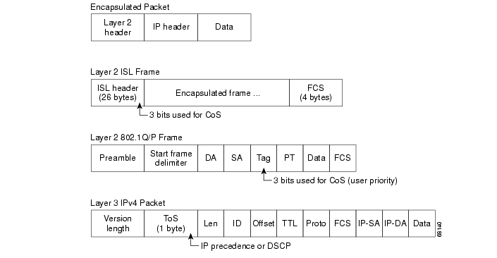
On interfaces configured as Layer-2 IEEE 802.1q trunks, all traffic is encapsulated in 802.1q frames except for traffic that is in the native VLAN. The IEEE 802.1q frame headers have a 2-byte Tag Control Information field that carries the Class of Service (CoS) value (0-7) in the three most-significant bits, which are called the User Priority bits. Figure C-1 illustrates the Layer 2 and Layer 3 QoS fields.
Figure C-1 Layer 2 and Layer 3 QoS Fields
Different switch models handle DSCP differently In the Cisco 7600 series and Cisco Catalyst 6500 series switches, the DSCP values are mapped to CoS values. The CoS values are in turn mapped to different transmit queues in the egress interface, and thresholds are used for buffer management. In the Cisco Catalyst 4000, DSCP values are mapped to transmit queues in the egress interface. Weighted Round Robin (WRR) and Strict Priority (SP) is used to service the transmit queues.
Table C-1 summarizes the service types and their corresponding DSCP, Ethernet CoS, and ATM Class values as used in the solution.
DiffServ Classification
The six most-significant bits of the DiffServ field are the DSCP values. [The last two bits in the DiffServ field were not defined within the DiffServ field architecture, but were later specified as Explicit Congestion Notification (ECN) bits.] As illustrated in Table C-2, the DiffServ standard uses the three most-significant bits (DS5, DS4, DS3) for precedence bits, and offers finer granularity through the use of the next three bits.
Four types of forwarding behavior are used: Class Selector (CS), Assured Forwarding (AF), Express Forwarding (EF), and Default.
Class Selector Values
Class Selector values have the format xxx000, where x is 0 or 1. These values enable backward compatibility with the older IP-Precedence scheme. For this solution, we recommend that VoIP or video signaling be marked with a Class of Service (CS) of 3. This class guarantees a minimum rate and has a DSCP value of 24 (0x011000). Table C-3 shows the class selector values for the DiffServ precedence levels.
Assured Forwarding
Assured Forwarding (AF) provides for the delivery of IP packets in four independently forwarded AF classes. Within each AF class, an IP packet can be assigned one of three different levels of drop precedence. This class is used when a service (application) requires a high probability of packets being forwarded, so long as the aggregate traffic from each site does not exceed the subscribed information rate (profile). Each of the four AF classes allocates a certain amount of forwarding resources, such as buffer space and bandwidth in each network node. When congestion occurs, the drop precedence of a packet determines the relative importance of the packet within the AF class.
For this solution, we recommend that all video be marked as with Precedence Level 4 (known as the Assured Forwarding class), with three levels of granularity. Therefore, multicast video has the lowest allowed drops (AF41), and unicast video has the second lowest (AF42). Table C-4 illustrates the drop thresholds and values for the Assured Forwarding classes.
Express Forwarding
Express forwarding is a low-loss, low-latency, low-jitter, assured-bandwidth, end-to-end service. Expedited Forwarding (EF) is defined as within the range for express forwarding. The DSCP value for EF is 46 (0x101110). For this solution, we recommend that VoIP traffic be marked as EF.
Default Class
The Default class is a best-effort class with no guaranteed rates. The DSCP value for Default is 0 (0x000000). For this solution, we recommend that high-speed data (HSD) be marked as Default. Table C-5 summarizes the recommended DSCP markings for the various services.
Table C-5 Recommended DSCP Markings
Multicast video
AF41
Unicast video 1 (50%)
AF42
Unicast video 2 (50%)
AF43
VoIP
EF
Signaling
CS3
HSD
Default
DSCP-to-CoS Mapping
The DSCP values in the IP packets are mapped to a CoS field in the Ethernet frame. These tags form part of the IEEE 802.1q header. On the DSL links, the ATM classes and CoS values are associated with the different services. The different services should have the CoS values shown in Table C-6.
For Ethernet interfaces, the default DSCP-to-CoS mapping is used, as shown in Table C-7.
Table C-7 Default Ethernet DSCP-to-CoS Mappings
0-7
0
8-15
1
16-23
2
24-31
3
32-39
4
40-47
5
48-55
6
56-63
7
Queueing and Thresholds
Each port in the switch has a series of input and output queues that are used as temporary storage areas for data. The queues are implemented in hardware ASICs for each port by means of two types of queues: a special strict-priority (SP) queue, and weighted queues. The SP queues are used for latency-sensitive traffic such as VoIP and are serviced until they are empty. The weighted queues are serviced only when the SP queue is empty. If a weighted queue is being serviced and a frame arrives in the SP queue, the scheduling of frames from the lower queues stops in order to process the frame in the SP queue. Only when the SP queue is empty does the scheduling of packets from the lower queue(s) recommence. Frames are placed in the different queues according to the CoS field in the frame.
Weighted Round Robin (WRR) is the scheduling algorithm used to empty the transmit queues. For each queue a weighting is used to dictate how much data is emptied from the queue before moving onto the next queue.
The Cisco 7600 series and Cisco Catalyst 6000 series also have a means of ensuring that buffers do not overflow. Thresholds are defined in the queues at which the congestion management algorithm can start dropping data. Different CoS values in the same queue can be mapped to different thresholds. Once the buffers have been fully utilized, tail-drop buffer management is used to drop newly arriving frames.
Queueing Structures on Cisco 7600 Series and Cisco Catalyst 6000 Series Line Cards
Each line card on the Cisco 7600 series and the Cisco Catalyst 6000 series has a unique queuing structure, as discussed below.
•
This line card uses the queue structure 1P1Q4T on the receive side and 1P2Q2T on the transmit side. Each GE ASIC on the line card supports a total of 2 Mbytes of buffer space, which is equally divided among each of the four GE ports under the control of that ASIC. This means that each GE port supports 512 kbytes of buffering for both receive and transmit. The receive-side buffer holds 73 kbytes, and the transmit-side buffer holds 439 kbytes.
•
These line cards use the queue structure 1Q8T on the receive side and 1P3Q8T on the transmit side. When a DFC3a is used, two receive queues are available, the new one being a SP queue. Each GE port supports 1.3 Mbytes of buffer space. The receive-side buffer holds 166 kbytes, and the transmit-side buffer holds 1.2 Mbytes.
•
This line card uses the queue structure 8Q8T on the receive side and 1P7Q8T on the transmit side. An SP queue is supported on the transmit side only. Each 10-GE port supports 16 Mbytes. The receive-side buffer holds 2 Mbytes, and the transmit-side buffer holds 14 Mbytes.
Queueing Structures on Cisco Catalyst 4000 Series Line Cards and Ports
Unlike the Cisco 7600 series and the Cisco Catalyst 6500 series, the Cisco Catalyst 4000 series line cards share the same queuing structure. The only difference is in the queue sizes for the 1-GE and 10-GE ports.
•
This line card has one receive queue and four transmit queues. One transmit queue can be configured as an SP queue. Each transmit queues holds 1920 packets.
•
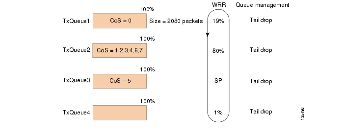
This SupV with 10-GE ports has one receive queue and four transmit queues. One transmit queue can be configured as an SP queue. Each transmit queue holds 2080 packets.
We recommend using three transmit queues for the six types of traffic on the network. In the lowest-priority queue, HSD should be carried. In the middle priority queue, VoD signaling, VoD high priority, VoD low priority, broadcast video, and network signaling should be carried. In the strict priority queue, VoIP should be carried. For more information about the DSCP and CoS values used in the solution, see DSCP-to-CoS Mapping.
The amount of buffering the network queuing provides for average video traffic is calculated below.
10-GE Symmetric Topology: Known and Unknown Queue Parameters
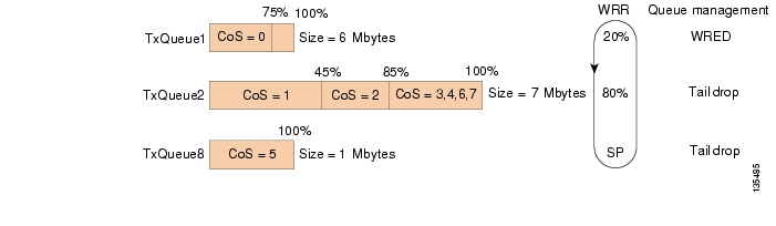
For the symmetric topology, 10-GE links are used in the transport. The amount of video traffic in the 10-GE transport approaches 7 Gbps. On the Cisco 7600 series and the Cisco Catalyst 6500 series, the transmit queue (TxQueue) for video is configured for 7 Mbytes. On the Cisco Catalyst 4500 series, the transmit queue for video is configured for approximately 3.2 Mbytes. Known and unknown queue parameters for the 10-GE symmetric topology are listed below.
link_speed
10,000,000,000 bits/sec
video_queue_size_Cat6k
7,000,000 bytes
(56,000,000 bits)
video_queue_size_Cat4k
3,200,000 bytes
(25,600,000 bits)
video_link_utilization
70%
1-GE Asymmetric Topology: Known and Unknown Queue Parameters
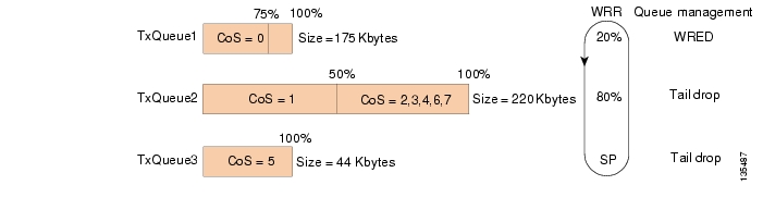
For the asymmetric topology, 1-GE links are used in the transport. The maximum amount of video traffic on any of the bidirectional links is approximately 700 Mbps. The amount of video traffic on the unidirectional links approaches 700 Mbps. Known and unknown queue parameters for the 1-GE asymmetric topology are listed below.
link_speed
1,000,000,000 bits/sec
video_queue_size_Cat6k
256,000 bytes
(2,048,000 bits)
video_queue_size_Cat4k
2,972,160 bytes
(~24,000,000 bits)
video_link_utilization
70%
1-GE Asymmetric and 10-GE Symmetric Topologies:
Known Threshold ParametersFor the 10-GE links, the following thresholds should be configured on the transmit queue that holds broadcast video, VoD, VoD signaling, and network signaling. These thresholds should be configured for tail drop.
For the Cisco 7600 series and Cisco Catalyst 6500 series that have thresholds in the queues, we recommend that two thresholds be used in the middle-priority queue to drop VoD low-priority and VoD high-priority traffic before dropping broadcast video traffic. For the 10-GE links, the following two thresholds should be configured on the transmit queue that holds broadcast video, VoD low, VoD high, VoD signaling, and network signaling. These thresholds should be configured for tail drop.
Known Parameters (10 GE)
For the 1-GE links, broadcast video is separated from the VoD traffic, so two thresholds should be configured on the transmit queue of the unidirectional links that hold VoD low, VoD high, VoD signaling, and network signaling.
VoD_low_threshold = 50%
VoD_high_threshold = 100%
These thresholds should be configured for tail drop.
Two types of queue management are used for HSD. On the Cisco 7600 series and the Cisco Catalyst 6500 series, Weighted Random Early Drop (WRED) should be configured between 75% and 100% queue utilization. On the Catalyst 4500 series, tail drop should be configured at 100%.
For VoIP, tail drop at 100% utilization should be configured on all three types of switches.
The following figures show the queue size, CoS-to-TxQueue mapping, queue thresholds, and WRR for the 10-GE symmetric and 1-GE asymmetric topologies with the following line cards:
•
•
•
•
Figure C-2 WS-X6704-10GE Queueing Structure (10-GE Symmetric)
Figure C-3 WS-X4513-10GE Queueing Structure (10-GE Symmetric)
Figure C-4 WS-X6816 Queueing Structure (1-GE Asymmetric)
Note
Figure C-5 WS-X4306-GB Queueing Structure (1-GE Asymmetric)
Table C-8 shows the queueing and thresholds used in the solution for a Cisco Catalyst 6000 series. The thresholds for the Cisco Catalyst 4000 series are the same as the queue length.
Table C-8 Solution Queueing and Thresholds for a Cisco Catalyst 6000 Series
HSD
TxQueue 1/20
~132
4.5
Multicast video
TxQueue 2/80
220
7
VoD high
220
~6
VoD low
110
3.15
Signaling
220
7
VoIP
TxQueue 3/SP1
44
1
1 Strict priority
![]()
![]()
![]()
![]()
![]()
![]()
![]()
![]()
Posted: Wed Sep 20 08:55:13 PDT 2006
All contents are Copyright © 1992--2006 Cisco Systems, Inc. All rights reserved.
Important Notices and Privacy Statement.