|
|

Table Of Contents
Routing Protocol Recommendations
ICMP Router Discovery Protocol
Open Shortest Path First Protocol
Cisco BTS 10200/Cisco ITP Profiles
D-link Base Profile Using ITP-Group (Distributed MTP3)
A-link Base Profile Using ITP-Group (Distributed MTP3)
E-link Configuration Using ITP-Group (Distributed MTP3)
F-link Configuration Using ITP-Group (Distributed MTP3)
Cisco BTS 10200/Cisco ITP Features
End-to-End Voice QoS Consideration
Planning and Design
Network designs will vary slightly from customer to customer due to differing sets of requirements and general technology and deployment preferences and methodologies. This chapter discusses elements of the Cisco BLISS for T1 design that should be considered before the solution is deployed.
Network Design
The initial step in planning and design is to collect the customer requirements to ensure that what the customer is looking for is something Cisco can deliver. The internal Network Commit Process validates and assures the fit between a Cisco Systems solution and a set of customer requirements to ensure that Cisco can deliver, deploy, and support the solution. The benefits of the process are as follows:
•
Align customer requirements with Cisco capabilities
•
•
•
This chapter includes the following sections:
•
•
•
•
Redundancy
This section identifies the key redundancy features of the design and points out portions of the design which lack redundancy and are single points of failure.
Table 2-1 summarizes the physical redundancy recommendations for the Cisco BLISS for T1 solution.
Cisco BTS 10200 Softswitch
The Cisco BTS 10200 Softswitch is comprised of two discrete, redundant components including the Call Agent (CA) and the Element Management System (EMS.) At any given time during operation, there is one pair of system components—CA and EMS—in an active state and the other pair is in a standby state. Also, the primary CA is in regular communication with the primary EMS and the secondary CA. This ensures that the CA's indexed databases (IDXs) are in sync with each other. Similarly, the primary EMS and secondary EMS use replication to sync their respective Oracle databases to each other.
Cisco ITPs
Cisco ITPs are deployed as a mated pair, which provides a fully redundant configuration. How traffic flows though the Cisco ITPs during a failure situation will be dependent on the method used for deployment. More detail on the two methods and the pros and cons of both will be covered in more detail in the "Configuring the Cisco ITP" section on page 5-6.
Cisco MGX 8880
In the Cisco BLISS for T1 solution, the Cisco MGX 8880 acts as the trunking gateway, providing connectivity to the PSTN. With respect to redundancy, the advantage of using the Cisco MGX 8880 in the solution is that the only active call impacting failure is a failure of a VISM. A VISM failure results in the loss of up to eight T1s. This is much better when compared to the Cisco AS5850 where an eRSC failure can result in the loss of up to 112 T1s or a line card failure can result in a loss of up to 28 T1s.
The Cisco MGX 8880 contains four main cards:
•
•
•
•
Each card is discussed in more detail in the following subsections.
VISM
The voice interworking service module (VISM) card has eight T1s. The total number of cards that can be put in each shelf of the Cisco MGX 8880 is 12 for a total of 24 cards across the upper and lower shelves. We recommend that the VISMs be deployed with 1:N redundancy to maximize the capacity of the MGX and provide a redundant VISM if one of the active VISMs fails.
PXM45
The PXM45 provides the control function for the MGX and interconnects the various line cards in the chassis. For example, the PXM45 interconnects the VISM and the RPM via a point-to-point ATM permanent virtual circuit (PVC). Redundancy for the PXM45 is provided through an active/standby configuration. The active card will process traffic while the standby card is idle. The active and standby cards communicate for synchronization and to determine if a switchover is necessary. In case of a PXM failure, the standby card becomes the active PXM and the MGX continues to process traffic normally. A PXM failure does not impact active calls.
RPM
The Route Processor Module (RPM) is a router on a blade that terminates the ATM PVC from the VISM and routes VoIP traffic between the Cisco BLISS for T1 core network and the VISM. RPM redundancy is provided through an active-active mechanism. Two RPMs are installed in the MGX chassis and a PVC from each is created to each VISM card in the chassis. One of the PVCs is designated active and the other standby. If an RPM fails, operations, administration, and maintenance (OAM) messages will be lost on the active PVC and the VISM will switch to the standby PVC and voice calls will continue to flow.
SRM3T3
The SRM Card multiplexes the T1s from VISM cards and aggregates them on the T3s on the SRM3T3 card. Redundancy for the SRM3T3 cards is provided through an active/standby configuration. If the PXM switches over to the secondary, the SRM card also switches to the secondary card. The PXM and SRM card are locked to each other from a redundancy perspective. For example, if PXM A and SRM A are locked together, and either of them fails, the MGX will failover to PXM B and SRM B. There are four SRM cards in the MGX, two for each shelf. T3 connectivity redundancy is provided with Y-cables.
Cisco 10000 ESR
The Cisco 10000 Edge Services Router (ESR) provides edge aggregation services in the Cisco BLISS for T1 architecture. It provides aggregation for T1s connecting customer premises equipment (CPE) to the T1 network as well as backhaul of customer traffic to the Cisco BLISS for T1 core. Redundancy in the Cisco 10000 ESR is provided through the use of dual power supplies and active/standby Performance Routing Engines (PRE-1). The Cisco 10000 ESR also supports Non Stop Forwarding and Stateful Switchover (NSF/SSO), which are mechanisms to prevent the disruption of IP traffic flow during a PRE switchover.
Catalyst 6509
We recommend deploying two identical Catalyst 6509 switches as a mated pair in the Cisco BLISS for T1 core network to provide full switch redundancy.
Catalyst 4506
We recommend deploying two identical Catalyst 4506 switches as a mated pair in the Cisco BLISS for T1 remote point of presence (POP) core networks to provide full switch redundancy.
Catalyst 3550
We recommend deploying two identical Catalyst 3550 switches as a mated pair in the Cisco BLISS for T1 remote POP core networks to provide full switch redundancy.
Cisco 7206
The Cisco 7206 provides routing services between the Internet and the Cisco BLISS for T1 network. The only redundancy on this platform is dual power supplies. If redundant connections to the Internet are a customer requirement, dual Cisco 7206 switches can be deployed with redundant connections to the Internet.
Cisco 2811 Terminal Server
This device is not redundant. Its only purpose is to provide out-of-band management for devices if in-band management is unavailable.
Cisco PIX Firewalls
Cisco PIX Firewalls are deployed in an active/standby mated pair configuration, hence there is no single point of failure.
Cisco IAD2430
The Cisco IAD2430 Series Integrated Access Device does not support any redundancy mechanisms. If the box fails, the entire unit has to be replaced.
DNS Server
DNS services are deployed on separate primary and secondary servers which provide full redundancy. In addition, active/standby load balancers are deployed to provide a single virtual IP address to all Cisco BLISS for T1 devices.
IP Addressing Recommendations
It is important that the IP addressing for the Cisco BTS 10200 Softswitch, as defined in the Network Site Survey document, be understood before designing the addressing scheme for the network.
In addition, actual public and private IP address assignments for the network should be done in conjunction with customer personnel. In general, the addressing of the Cisco BLISS for T1 network follows the same guidelines as IP addressing for any data communications network, keeping the following guidelines in mind.
•
•
•
Routing Protocol Recommendations
This section describes the routing and related redundancy aspects of the MGCP signaling path to and from the Cisco BTS 10200 for the Cisco BLISS for T1 solution.
Signaling redundancy is provided by:
•
•
When selecting a routing protocol for the Cisco BLISS for T1 solution things to consider are:
•
•
•
•
•
Considering the above requirements, OSPF was selected for the Cisco BLISS for T1 solution.
ICMP Router Discovery Protocol
ICMP Router Discovery Protocol (IRDP) is defined by RFC 1256 and is an extension to ICMP that allows routers to notify hosts of their presence. This is the mechanism used by the Call Agent to converge its default route if a default route fails. For any failure between the Call Agents and the Catalyst 6509 switches, the host should adjust its default route within 10 seconds. This only impacts the MGCP signaling traffic from the Call Agent to MGCP endpoints. RTP traffic does not traverse the Call Agent and therefore is not affected.
IRDP defines Router Advertisement and Router Solicitation messages. Router Advertisements are sent in the period between the values configured for `ip irdp minadvertinterval x' and `ip irdp maxadvertinterval y.' For the Cisco BLISS for T1 solution, these will be set to their lowest possible values (between 3 and 4 seconds). These advertisements can be sent to the multicast address 224.0.0.1 or to the all 1's broadcast address, 255.255.255.255. The IRDP message includes a lifetime field and a preference level that will be important to the convergence times. The lifetime field (configured by `ip irdp holdtime x') is used to tell the host how long the advertisement should remain valid. This would allow for 2 to 3 advertisement losses before invalidating the advertisement.
Router Solicitations are used by the host during initialization time to request an early advertisement. An early advertisement is useful in environments where the advertisement interval is very long. Because the Cisco BLISS for T1 solution will use an update interval of 3 to 4 seconds, the solicitation is not that important. The host, however, will still send it when its process starts.
Open Shortest Path First Protocol
Open Shortest Path First (OSPF) is a link state routing protocol that quickly converges around failures in a manner that does not produce routing loops. Items that should be considered that affect OSPF convergence times are as follows:
•
OSPF Designated Router Selection
For broadcast media, OSPF defines a Designated Router Selection process that determines the Designated Router and Backup Designated Router. The Designated Router is responsible for keeping the databases of all other routers on the subnet synchronized. When the Designated Router fails, the Backup Designated Router takes over, but can take additional time to synchronize all of the routers on the subnet. The time required to synchronize depends on the number of routes in the routing table. The Cisco BLISS for T1 design should not allow any of the trunking gateways or announcement servers to become the Designated Router or Backup Designated Router. This can be accomplished by setting the `ip ospf priority 0' in those devices.
Neighbor Adjacency
OSPF routers send hello multicast packets to maintain the neighbor adjacency. The OSPF hello interval and dead time are key factors in determining network convergence time. If necessary, OSPF endpoint hello intervals can be adjusted downward to improve the update time of the link state database if a neighbor router fails.
OSPF Cost
OSPF cost provides a mechanism to prefer one path over another through the network when multiple paths exist. It allows the path that traffic takes through the network to be determined beforehand for both normal and failure scenarios, which provides the necessary level of control to ensure continued operation of voice services.
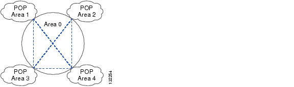
OSPF Area
It is important to consider not only the current BLISS network design but also future network growth when designing OSPF areas. The purpose of OSPF areas is to reduce routing table size and prevent network events such as link failures or device outages in one area from affecting devices in other areas. In general, each POP should be defined as its own area with the core network connecting the POPs designated as area 0. See Figure 2-1.
Figure 2-1 OSPF Area
OSPF and PIX
The recommended release for the Cisco PIX Firewall is Version 6.3. This version includes support for the OSPF routing protocol which allows the Cisco PIX Firewall full routing functionality within the OSPF area. Note that when enabling OSPF on the Cisco PIX Firewall while using MD5 authentication, the Cisco PIX Firewall does not accept spaces within OSPF authentication keys or message digests, but Cisco IOS does. This may create compatibility issues when a Cisco PIX Firewall tries to exchange OSPF messages in an adjacent Cisco IOS device. Up to two OSPF process can be defined in the Cisco PIX Firewall and only broadcast networks are supported. OSPF features not supported by the Cisco PIX Firewall Version 6.3 include:
•
•
•
•
•
SS7 ITP Considerations
The following items should be considered in the deployment of the Cisco ITPs for SS7 connectivity:
ITP Hardware Redundancy
The Cisco 7507 platform is an internally hardware-redundant solution. The Cisco BLISS for T1 solution will not include internal hardware redundancy as a possible fully redundant solution. The reasons are:
•
•
Also note that some customers felt that the Cisco 7507 with full internal redundancy configured did not have sufficient density and preferred the Cisco 7513 platform. Note however that the Cisco 7507 or Cisco 7513 may be part of a fully redundant SG Mated Pair.
Platform Redundancy
ITP redundancy can also be accomplished by connecting two ITP nodes together. This can be done in one of two ways. The ITPs can be connected as an SG Mated Pair or as an ITP-Group.
An SG Mated Pair is utilized whenever the customer wants to connect to the Service Provider SS7 Network via D-links. The ITP-Group is used whenever the customer wants to connect to the Service Provider SS7 Network via A-, E-, or F-links.
When provisioning the Cisco BTS 10200, these two forms of redundancy cannot be combined. If there are two Signaling Gateway Processes (SGPs) defined for one signaling gateway (SG), then that SG will be the only SG in the associated SG Group. Likewise, if there are two SGs in an SG Group, then a second SGP cannot be added to either of the associated SGs.
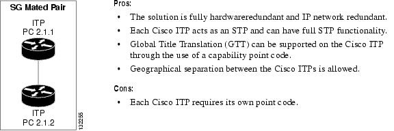
SG Mated Pair
As an SG Mated Pair connection, each Cisco ITP has its own point code and acts as a signalling termination point (STP) that connects to other STPs in the SS7 network via D-links. Any Cisco ITP can be used in this form of redundancy.
Figure 2-2 SG Mated Pair
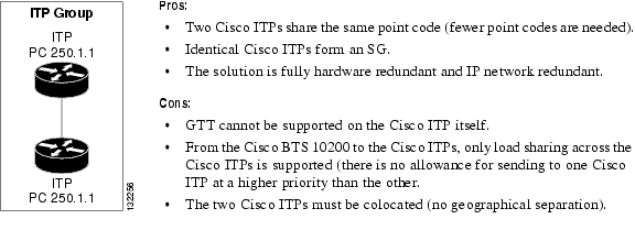
ITP-Group
In an ITP group (the SIGTRAN Distributed MTP feature) configuration, each Cisco ITP acts as a physical SGP. Two of these physical SGP processes are connected together to form one logical SG. In this configuration, both Cisco ITPs share the same point code value. Note that this form of redundancy is not available for the Cisco 7500 because it has internal hardware redundancy. It is available for the Cisco 2651 and Cisco 7300 series ITPs.
Figure 2-3 ITP-Group
Cisco BTS 10200/Cisco ITP Profiles
There are four Cisco BTS 10200/Cisco ITP profiles on which all customer-offered profiles are based. In general, the combination of a base profile, as described in this section, and one or more features, as described in the "Cisco BTS 10200/Cisco ITP Features" section, form the profiles described in the "Customer-Offered Cisco BTS 10200/Cisco ITP Profiles" section on page 5-10.
The four base Cisco BTS 10200/Cisco ITP profiles are as follows:
•
•
•
•
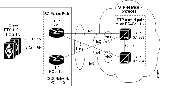
D-link Base Profile Using ITP-Group (Distributed MTP3)
In this configuration ( Figure 2-4), each Cisco ITP acts as an STP and has its own point code which is different than any of the point codes on the Cisco BTS 10200 Softswitch. The Cisco ITPs are connected to the SS7 network using diagonal D-links.
Figure 2-4 D-link Base Profile
Pros:
•
•
•
•
•
•
•
•
•
Cons:
•
•
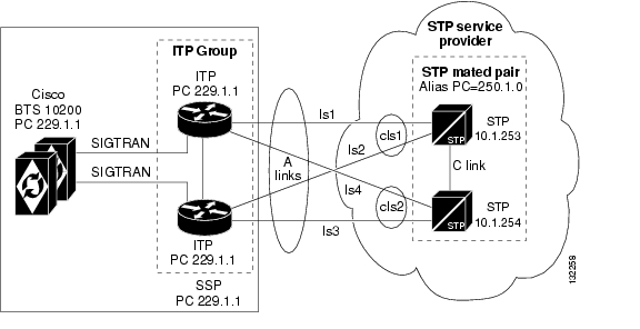
A-link Base Profile Using ITP-Group (Distributed MTP3)
In this profile ( Figure 2-5), both Cisco ITPs and the Cisco BTS 10200 are viewed as a single point code Signaling End Point (SEP) from the service provider's SS7 network. The ITP-Group consisting of two Cisco ITPs acts as the SS7 proxy for the Cisco BTS 10200. The Cisco ITPs connect to the SS7 network using A-links.
Note
Figure 2-5 A-link Base Profile
Pros:
•
•
•
•
Cons:
•
•
•
•
•
•
E-link Configuration Using ITP-Group (Distributed MTP3)
An E-link is basically the same as an A-link (except it serves as a backup in case all A-link connections become unavailable). It has the basic setup and list of pros and cons as the A-link configuration.
F-link Configuration Using ITP-Group (Distributed MTP3)
The F-link configuration is similar to the A-link configuration except that instead of connecting to an STP via `A' links, it connects to another SEP in the SS7 network via fully associated F-links. It has the basic setup and list of pros and cons as the A-link configuration.
Cisco BTS 10200/Cisco ITP Features
The following is a list of features that are delivered through various configurations and combinations of the Cisco BTS 10200 and the Cisco ITP. These features are built on top of the base configuration profiles defined in the "Cisco BTS 10200/Cisco ITP Profiles" section to form the profiles defined in the "Customer-Offered Cisco BTS 10200/Cisco ITP Profiles" section on page 5-10.
•
•
•
•
•
QoS Recommendations
The goal of quality of service (QoS) is to help reduce or eliminate delay of voice packets that travel across a network. In the Cisco BLISS for T1 solution, the method used is Class-Based Weighted Fair Queuing (CBWFQ) with a priority queue also known as Low Latency Queuing (LLQ). In this scenario, traffic is classified as voice or data and queued such that voice always gets priority and data receives best-effort service. The customer is free to define the classifications of traffic in a more granular fashion, but voice must always get priority over all other types of data traffic.
End-to-End Voice Delays
Based on ITU-T G.114 recommendations, end-to-end one-way delay of 150 ms is acceptable. In this section we use the codec G.726 as an example to discuss the end-to-end delay budget calculation.
In Cisco IOS VoIP products, the digital signal processor (DSP) generates a speech sample every 10 ms when using G.726. Two of the samples are then placed within one packet. The packet delay is then 20 ms. A lookahead of 5 ms occurs between the frames. The speech samples sent in one packet can be configured by increasing or decreasing the packetization interval. Table 2-2 shows end-to-end VoIP packet delay budget items.
As seen in Table 2-2, there are certain unknown delay factors, as indicated by the question marks (?). For calls made across a WAN in a public switched network, the network delay could be a big contributor. The customer can also adjust dejitter buffer size to achieve the balance between jitter and delay.
If the buffer is too small, the end-to-end delay can be minimized for individual voice packets. However, the samples are held in the buffer for too short a time, and variations in delay may cause the buffer to underrun and cause gaps in the speech. If the buffer is too large, the samples are held for too long a time, the buffer can overrun, and the dropped packets again cause gaps in the speech. In addition, the end-to-end packet delay may rise to unacceptable levels. The Playout Buffer is the command used in VoIP in order to adjust the jitter buffer size to achieve balance between jitter and delay.
The queuing delay at various network components is the major contributor of the variable delay in a VoIP network. This includes the queuing/buffer delay in the WAN if a public switched network is used. QoS techniques that can be used to minimize the queuing delay in customer network environments are discussed in the next section. Using the information collected in Table 2-2, a delay budget needs to be calculated. For example, if the WAN delay is estimated at 20 ms, dejitter buffer is 40 ms, and queuing delay is 25 ms, then the end-to-end delay budget is 29.35 + 20 + 40 + 25 ms = 114.35 ms.
End-to-End Voice QoS Consideration
Cisco IOS provides various QoS tools for VoIP networks. An overall QoS strategy needs to be developed to utilize these QoS features to achieve the best voice service quality. QoS techniques such as classification at the network edge, queuing and policing at the output queue of the network aggregation and core points, need to be applied in the network. For the queuing and policing QoS techniques, LLQ is recommended to guarantee bandwidth and latency for different classes of traffic. It assigns absolute high priority to voice traffic and distributes the rest of the link bandwidth fairly among the data traffic. Thus LLQ helps minimize the variable queuing delay as listed in the end-to-end delay budget chart.
In the Cisco BLISS for T1 solution, LLQ has to be applied to all devices that are responsible for transmitting voice and data traffic. Notable components are the Cisco IAD, Cisco 4506 switch, and the Cisco 10000 ESR. The following sections cover examples of these configurations.
LLQ Configuration Example Using MQC
Low Latency Queuing (LLQ) is a combination of Priority Queuing (PQ) and Class Based Weighted Fair Queuing (CBWFQ), meaning LLQ brings the Priority Queuing features into the CBWFQ.
This allows voice strict priority and data to optionally be further classified to provide differentiated classes of service. In some areas of this document that state Priority Queuing, what we are referring to is the PQ functionality that is part of Low Latency Queuing.
The following example illustrates the configuration of priority queuing on a Cisco IAD.
<--- snip--->class-map match-all MGCP <--- create a class for signaling traffic called MGCPmatch ip precedence 4 <--- all traffic with precedence 4 is placed into the class MGCPclass-map match-all RTP <--- create a class for RTP traffic called RTPmatch ip precedence 5 <--- all traffic with precedence 5 is placed into the class RTP!policy-map T1_QOS <--- create a policy called T1_QOSclass RTP <--- for traffic that is in the class RTPpriority percent 90 <--- assign RTP class traffic to the priority queue (up to 90% avail ban)class MGCPbandwidth percent 4!interface Multilink1service-policy output T1_QOS <--- apply the policy T1-QOS to the interface in the outbound direction.....multilink-group 1!LLQ is configured with the priority command. To enqueue classified traffic to the strict priority queue, you configure the priority command for the class after you specify the named class within a policy map. (Classes to which the priority command is applied are considered priority classes.) Within a policy map, you can give one or more classes priority status. When multiple classes within a single policy map are configured as priority classes, all traffic from them is enqueued to the same single, strict priority queue.
QoS Configuration Example on Catalyst Platforms
Catalyst 4506
...qos map dscp 32 33 34 to tx-queue 2qos map dscp 35 36 37 38 39 40 41 42 to tx-queue 4qos map dscp 43 44 45 to tx-queue 4qos map dscp 24 25 to cos 2qos map dscp 33 to cos 3qos map dscp 40 41 42 43 44 45 to cos 4qos map cos 3 to dscp 26qos map cos 4 to dscp 34qos map cos 5 to dscp 46qos...interface GigabitEthernet6/3...no switchportip address 172.17.66.5 255.255.255.252qos trust dscptx-queue 3priority high...Catalyst 6509
....mls qos map dscp-cos 24 25 to 2mls qos map dscp-cos 32 33 to 3mls qos map dscp-cos 40 41 42 43 44 45 to 4mls qos map cos-dscp 0 8 16 26 34 46 48 56mls qos map ip-prec-dscp 0 8 16 26 34 46 48 56mls qos...interface GigabitEthernet1/1...no ip unreachablesno ip proxy-arplogging event link-statuswrr-queue cos-map 1 1 0 1 2wrr-queue cos-map 1 2 3wrr-queue cos-map 2 1 4 6 7wrr-queue cos-map 2 2 5mls qos trust dscpVoice Loss Plan
A voice loss plan needs to be created in order to optimize voice quality. The purpose of the loss plan is to reduce the effects of echo, distortion, clipping, and noise within the voice environment and counter the effects of power loss due to signal transmission. Inserted loss appears once in the Primary Signal Path and twice in the Talker and Listener Echo Paths.
For more information on the voice loss plan and echo, refer to http://www.cisco.com/en/US/tech/tk652/ tk701/technologies_white_paper09186a00800d6b68.shtml
![]()
![]()
![]()
![]()
![]()
![]()
![]()
![]()
Posted: Fri May 6 08:27:27 PDT 2005
All contents are Copyright © 1992--2005 Cisco Systems, Inc. All rights reserved.
Important Notices and Privacy Statement.