|
|

Table Of Contents
Configuring the Cisco BTS 10200 Softswitch
Configuring Cisco ITP Routing Over SIGTRAN
Provisioning SS7-Related Elements of the Cisco BTS 10200
Customer-Offered Cisco BTS 10200/Cisco ITP Profiles
Configuring the Cisco 10000 ESR
Configuring the Cisco PIX Firewall
Configuring the Trunking Gateway
Cisco AS5850 BTS Configuration
Configuring the Solution
This chapter covers configuration and provisioning of the major components of the Cisco BLISS for T1 solution where those configurations and provisioning are unique to the solution. For general component configuration guidance, refer to the documentation on the Cisco Technical Support & Documentation website located at http://www.cisco.com/en/US/support/index.html.
This chapter includes the following sections:
•
Configuring the Cisco BTS 10200 Softswitch
•
•
•
•
•
•
Configuring the Cisco BTS 10200 Softswitch
To configure the Cisco BTS 10200 Softswitch, perform the following steps:
Step 1
http://www.cisco.com/univercd/cc/td/doc/product/voice/bts10200/bts4_4/install/surveys/index.htm
Step 2
http://www.cisco.com/univercd/cc/td/doc/product/voice/bts10200/bts4_4/install/index.htm
Step 3
http://www.cisco.com/univercd/cc/td/doc/product/voice/bts10200/bts4_4/install/index.htm
Step 4
http://www.cisco.com/univercd/cc/td/doc/product/voice/bts10200/bts4_4/install/index.htm
Upon completion of this procedure, the Cisco BTS 10200 software can be started and voice services provisioning can begin.
Configuring the Catalyst 6509
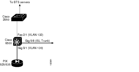
General setup of the Catalyst 6509 switch involves configuring the interfaces, VLANs, and routing protocols to support the network design developed prior to this installation. Figure 5-1 shows the interfaces to the Catalyst 6509 switch. Following Figure 5-11 are excerpts from a Catalyst 6509 configuration that illustrate the items that have to be configured to support the Cisco BLISS for T1 solution. Only those items that are unique to the Cisco BLISS T1 solution are highlighted. For general guidance on configuring the Catalyst 6509 switch, refer to the Cisco documentation located at http://www.cisco.com/univercd/home/home.htm.
Note
Figure 5-1 Reference Diagram for Catalyst 6509 Configuration
!< Begin Configuration >Current configuration: 36344 bytes...!< The class map section below defines 3 traffic classes for voice signaling, voice bearer, and telnet traffic. There are a couple of approaches that can be used to do this. One is to trust traffic that has been marked at the edge and use the TOS/DSCP values to queue traffic that traverses the network or as in this example do not trust any traffic and classify it at each hop in the network. >class-map match-all voice-signalingdescription Match MGCP Signaling and Backhaulmatch access-group 122class-map match-all voice-rtpdescription Match Voice Real-Time Transport Protocolmatch access-group 121class-map match-all gold-datadescription Match Telnet Managementmatch access-group 123!< This section defines the policies that assign the appropriate DSCP value to the classified traffic. The DSCP values used are based on Cisco recommendations. For further information on QOS in voice networks refer to the Solutions Reference Network Design for Quality of Service Design. >policy-map voicedescription Service Policy for QoS Classificationclass voice-rtpset ip dscp 46class voice-signalingset ip dscp 26class gold-dataset ip dscp 10!mls flow ip interface-fullmls flow ipx destinationmls sampling time-based 64mls aclmerge algorithm odmmls aclmerge odm optimizations!< The DSCP-to-CoS map is used to map the final DSCP classification to a final CoS. This final map determines the output queue and threshold to which the packet is assigned. The CoS map is written into the ISL header or 802.1Q tag of the transmitted packet on trunk interfaces and contains a table of 64 DSCP values and the corresponding CoS values >mls qos map dscp-cos 24 25 to 2mls qos map dscp-cos 32 33 to 3mls qos map dscp-cos 40 41 42 43 44 45 to 4!< The CoS-to-DSCP map is used to map the CoS of packets arriving on trusted interfaces (or flows) to a DSCP where the trust type is trust-cos. This map is a table of eight CoS values (0 through 7) and their corresponding DSCP values. >mls qos map cos-dscp 0 8 16 26 34 46 48 56!< The IP Precedence-to-DSCP map is used to map the IP precedence of IP packets arriving on trusted interfaces (or flows) to a DSCP when the trust type is trust-ipprec. >mls qos map ip-prec-dscp 0 8 16 26 34 46 48 56!< enable QOS globally >mls qos!...interface FastEthernet2/1description Uplink to BTS 2950no ip addresslogging event link-statusspeed 100duplex full!< The next 4 lines tell the 6509 who to map CoS values to drop thresholds for a queue >wrr-queue cos-map 1 1 0 1 2wrr-queue cos-map 1 2 3wrr-queue cos-map 2 1 4 6 7wrr-queue cos-map 2 2 5!< In VLAN-based mode, the policy map attached to the Layer 2 interface is ignored, and QoS is driven by the policy map attached to the corresponding VLAN interface. >mls qos vlan-basedswitchportswitchport access vlan 132switchport mode access...interface GigabitEthernet9/1description L2 interface to PIX525 Inside interfaceno ip addresslogging event link-statuswrr-queue cos-map 1 1 0 1 2wrr-queue cos-map 1 2 3wrr-queue cos-map 2 1 4 6 7wrr-queue cos-map 2 2 5!< Specifies that the TOS bits in the incoming packet is a DSCP value and that it is trusted. >mls qos trust dscpswitchportswitchport access vlan 130switchport mode accessspanning-tree portfast...interface GigabitEthernet9/8description ISL FX Trunk to tpakptp02btsr02 g9/8no ip addresslogging event link-statuswrr-queue cos-map 1 1 0 1 2wrr-queue cos-map 1 2 3wrr-queue cos-map 2 1 4 6 7wrr-queue cos-map 2 2 5mls qos trust dscpswitchportswitchport trunk encapsulation islswitchport trunk allowed vlan 1-912,914-4094switchport trunk pruning vlan 2-900,902-1001switchport mode trunk!interface Vlan130description BTS DMZ PIX Firewalls Insideip address 10.152.130.3 255.255.255.0no ip redirectsno ip unreachablesno ip proxy-arpip ospf authentication message-digestip ospf message-digest-key 1 md5 7 12345ip ospf cost 1ip ospf hello-interval 3ip ospf priority 110logging event link-statusload-interval 30arp timeout 1200!interface Vlan132description Primary (1st) BTS External Subnetip address 10.152.132.3 255.255.255.0no ip redirectsno ip unreachablesno ip proxy-arp!< Enable ICMP Router Discover Protocol (IRDP) >ip irdp!< Max interval between IRDP advertisements >ip irdp maxadvertinterval 4!< Min interval between IRDP advertisements >ip irdp minadvertinterval 3!< IRDP advertisement lifetime >ip irdp holdtime 10!< Sets the preference for a device sending IRDP advertisements >ip irdp preference 110logging event link-statusload-interval 30!< This line applies the policy defined for voice signaling, voice bearer, and telnet traffic. >service-policy input voicearp timeout 1200!interface Vlan133description Secondary (2nd) BTS External Subnetip address 10.152.133.3 255.255.255.0no ip redirectsno ip unreachablesno ip proxy-arpip irdpip irdp maxadvertinterval 4ip irdp minadvertinterval 3ip irdp holdtime 10ip irdp preference 100logging event link-statusload-interval 30service-policy input voicearp timeout 1200...!!< These are the access lists used by the class-map statements to select the traffic for a particular class >access-list 121 remark Voice RTP Trafficaccess-list 121 permit udp 10.0.0.0 0.255.255.255 range 16384 32767 anyaccess-list 121 permit udp 172.17.0.0 0.0.255.255 range 16384 32767 anyaccess-list 121 permit udp any 10.0.0.0 0.255.255.255 range 16384 32767access-list 121 permit udp any 172.17.0.0 0.0.255.255 range 16384 32767access-list 122 remark MGCP Voice Signalingaccess-list 122 permit udp any any range 2427 2428access-list 122 permit udp any any range 2727 2728access-list 122 permit udp any any range 5555 5556!< The next two statement allow MGCP ping traffic from the BTS to the media gateway >access-list 122 permit udp any eq 12100 anyaccess-list 122 permit udp any any eq 12100access-list 123 remark Gold Dataaccess-list 123 permit tcp any any range 22 telnetaccess-list 123 permit udp any 10.152.136.32 0.0.1.7 eq domainaccess-list 123 permit udp any 10.170.136.32 0.0.1.7 eq domain!...endCisco IOS SLB for DNS Redundancy
The recommended method for providing Domain Name Server (DNS) redundancy to the Cisco BLISS for T1 solution is to use external load balancers with the Cisco IOS Server Load Balancer (SLB) on the Catalyst 6509. The configuration is conceptually the same for an external Cisco CSS 11500 switch.
...ip slb serverfarm DNS-FARM <--- define the server farm that contains the DNS serversnat serverprobe DNS-PROBE <--- reference to probe that monitors the DNS application!real 10.151.66.138 <--- IP address of primary DNS serverinservice!real 10.151.66.148 <--- IP address of the secondary DNS serverinservice!ip slb vserver DNS-SERVER <--- define the virtual servervirtual 10.151.66.99 tcp 53 <--- specify virtual IP address and port for the server farmserverfarm DNS-FARM <--- specify the server farminservice standby VLAN-66 <--- VLAN to communicate to secondary 6509 for redundancyConfiguring the Cisco ITP
This section describes the procedures for configuring the Cisco IP Transfer Points (ITPs) to provide SS7 connectivity. It includes the following sub-sections:
•
•
•
Configuring Cisco ITP Routing Over SIGTRAN
Cisco ITP configuration is straightforward to those who have a basic understanding of Cisco IOS and how to configure SS7 network elements. This section provides an overview of the SIGTRAN-specific areas of the Cisco ITP configuration because the concepts and terminologies used may be new to the user. For a complete guide to configuring the Cisco ITP, go to the following URL:
http://www.cisco.com/univercd/cc/td/doc/product/wireless/moblwrls/itp/25sw/index.htm
You can also view Cisco ITP example configurations at the following URL:
Application Servers, Routing Keys, and Routing Context
The IETF SIGTRAN documentation defines how a signaling gateway (such as the Cisco ITP) routes traffic from the SS7 service provider toward a SIGTRAN-enabled IP endpoint (such as the Cisco BTS 10200). The following are associated descriptive terms:
•
•
•
•
AS and ASP Configuration Example
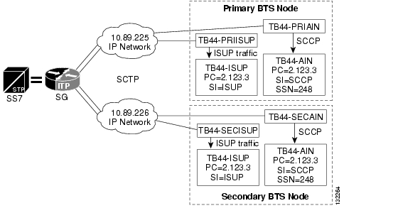
This section includes a basic configuration example and a diagram which depicts the example. Refer to Figure 5-2 when reading the following configuration information.
The following ASP configuration defines the primary-side TSA process. TB44-PRIAIN is the variable name of the ASP, 12205 is the remote (BTS) port number, 14001 is the local (ITP) port number, and sua defines the layer 3 SIGTRAN protocol used to transfer information to the ASP. This configuration also shows two IP addresses of the Cisco BTS 10200 that the TSA process uses for SUA communication.
cs7 asp TB44-PRIAIN 12205 14001 suaremote-ip 10.89.225.234remote-ip 10.89.226.234The following configuration is very similar to the first, except that it defines information for the secondary-side TSA process.
cs7 asp TB44-SECAIN 12205 14001 suaremote-ip 10.89.225.235remote-ip 10.89.226.235Figure 5-2 Configuring a Basic AS and ASP on the Cisco ITP
The following configuration is similar to the previous examples except that it defines an ASP that uses m3ua to transfer information to the ASP. This configuration is for the primary-side SGA process.
cs7 asp TB44-PRIISUP 11146 2905 m3uaremote-ip 10.89.225.234remote-ip 10.89.226.234The following configuration is for the secondary-side SGA process.
cs7 asp TB44-SECISUP 11146 2905 m3uaremote-ip 10.89.225.235remote-ip 10.89.226.235The AS configuration defines the routing key, which defines a filter for the traffic that will be sent toward the associated ASPs. The filter is based on parameters (such as DPC, OPC, CIC range, service indicator, and SSN) within incoming messages from the SS7 network.
•
•
•
•
Note
cs7 as TB44-ISUP m3uarouting-key 1 2.1.3 si isupasp TB44-PRIISUPasp TB44-SECISUPtraffic-mode overridenetwork-appearance 1The following AS definition processes AIN traffic. It defines an ASP that uses sua instead of m3ua as the SIGTRAN protocol that communicates with this AS. The routing key definition includes DPC and SI values as well as an SSN value of 248 to further refine the filter.
cs7 as TB44-AIN suarouting-key 2 2.1.3 si sccp ssn 248asp TB44-SECAINasp TB44-PRIAINtraffic-mode overridenetwork-appearance 1Overlapping AS Configurations
The following AS configuration example is similar to the ones in the previous section, but has more information in the routing key definition.
In this example, the AS routes messages toward asp PRI_ISUP_BTS2 or SEC_ISUP_BTS2. The routing key has a routing context value of 10. The routing key defines the DPC value as 2.1.3, and the OPC value as 3.50.3. This OPC has a mask value of 255.255.255 (which means all bits of the OPC will be considered when routing). It defines a service indicator (si) of ISUP and a cic range of 1 to 23.
Note
cs7 as ISUP_BTS1 m3uarouting-key 10 2.1.3 opc 3.50.3 255.255.255 si isup cic 1 23asp PRI_ISUP_BTS2asp SEC_ISUP_BTS2traffic-mode overridenetwork-appearance 1This AS (ISUP_BTS1) and the AS in the previous section (TB44-ISUP) both route ISUP messages from the SS7 network that have DPC values of 2.1.3. The question becomes Which ASP will the Cisco ITP route toward when the DPC in the incoming ISUP message is 2.1.3? The answer is the one that matches best. ISUP_BTS1 requires that four parameters from the incoming SS7 message match its routing key. TB44-ISUP only requires two parameters. If all four parameters of routing-key 10 match, then ISUP_BTS1 will be chosen. If only three parameters of routing-key 10 match, then routing key 1 is a better match and TB44-ISUP will be chosen to process the message.
Provisioning SS7-Related Elements of the Cisco BTS 10200
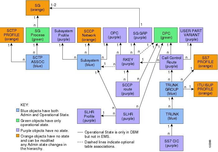
Each subsection of the "Customer-Offered Cisco BTS 10200/Cisco ITP Profiles" section that follows includes example provisioning for the Cisco BTS 10200 that is related to the associated ITP profile. Refer to Figure 5-3 when provisioning SS7-related components for the Cisco BTS 10200. Note that the objects must be provisioned from the top down (for instance, the SG is provisioned before the SG Process or SG Group).
For a complete description of provisioning SS7-related objects on the Cisco BTS 10200 in Release 4.4, refer to http://lbj/push_targets1/ucdit/cc/td/doc/product/voice/bts10200/bts4_1/provgd/41_ss7.htm.
Figure 5-3 Cisco BTS 10200 SIGTRAN SS7 Object Diagram
Customer-Offered Cisco BTS 10200/Cisco ITP Profiles
This section includes several Cisco BTS 10200/Cisco ITP profiles that are offered to customers. This section provides the basic D-link and A-link profiles and the building blocks and then adds features to create more complex profiles.
Several features can be combined to form hybrid profiles not listed in the following subsections.
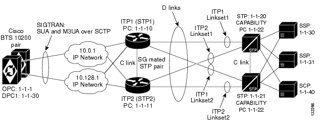
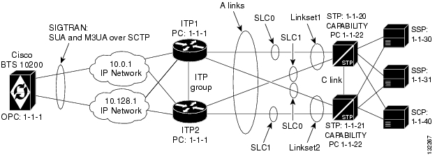
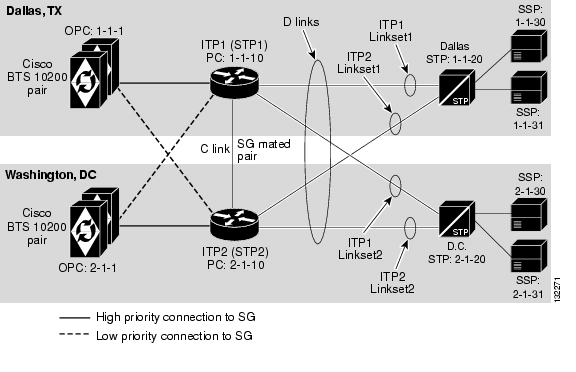
Basic D-link Profile
The basic D-link profile is used when a customer wants to access the SS7 network using D-links.
Figure 5-4 Basic D-link Profile
For pros and cons of this profile, refer to the "SG Mated Pair" section on page 2-9.
Usage
The Basic D-link Profile is used if the customer wants multiple OPCs on the Cisco BTS 10200. It is also used when the customer wants global title translation (GTT) support on the Cisco ITP. It provides for geographical separation of Cisco ITPs (see the "Geographically Distributed D-link Profile with SG Routing Priority" section).
ITP Configuration Information
This section provides a configuration example for ITP1 and ITP2 in the basic D-link profile. For additional Cisco ITP configuration information, see the Cisco ITP Configuration Guide and Command Reference at the following URL:
http://www.cisco.com/univercd/cc/td/doc/product/wireless/moblwrls/itp/25sw/itp25swi.pdf
The Cisco ITP Configuration Guide and Command Reference is a very large document. In particular, focus on the following sections:
•
•
•
For other Cisco ITP example configurations, see the following URL:
ITP1 Configuration
######################################################################## ITP1 - The first ITP in the sg-pair (each ITP in the sg-pair functions as an STP).#######################################################################Current configuration : 3470 bytes!version 12.2service timestamps debug datetime msecservice timestamps log datetime msecno service password-encryption!hostname ITP1!boot-start-markerboot system flash c2600-itp-mz.topsail_s_nightly_040915boot-end-marker!redundancy inter-device!enable secret 5 $1$XCoU$j0Y2wFRoks2pocHa1gHhi0enable password cisco!ipc zone defaultassociation 1no shutdownprotocol sctplocal-port 9001local-ip 10.0.1.54local-ip 10.128.1.239remote-port 9000remote-ip 10.0.1.55remote-ip 10.128.1.240!memory-size iomem 20ip subnet-zero!ip domain-name cisco.comip name-server 10.0.0.6!## Note that for the D-link configuration (SG Mated Pair) configuration, the local# point code value is 1.1.10, which is different than the BTS OPC and the other ITP (ITP1)# that makes up the SG Mated Pair.#cs7 variant ANSIcs7 point-code 1.1.10!controller E1 0/0framing NO-CRC4channel-group 0 timeslots 1!controller E1 0/1framing NO-CRC4channel-group 0 timeslots 1!controller E1 0/2shutdown!controller E1 0/3shutdown!interface Serial0/0:0description connect to link 0 of STP 1-1-20no ip addressencapsulation mtp2no clns route-cache!interface Serial0/1:0description connect to link 0 of STP 1-1-21no ip addressencapsulation mtp2no clns route-cacheinterface FastEthernet0/0ip address 10.0.1.54 255.255.0.0speed autohalf-duplexno clns route-cache!interface FastEthernet0/1ip address 10.128.1.239 255.255.0.0speed autohalf-duplexno clns route-cache### In the D-link configuration, instead of defining a cs7 group (as is done in# the A-link configuration, a "local-peer" and "mated-sg" are defined. Here# we define the local-peer which is the local definition for the C-link connection# between the two ITPs that make up the redundant STP pair.##cs7 local-peer 7000local-ip 10.0.1.54local-ip 10.128.1.239## Linkset definitions. Note: the number after `link' represents SLC#cs7 linkset lset1chn 1.1.20link 0 Serial0/0:0!cs7 linkset lset2chn 1.1.21link 0 Serial0/1:0## C-link linkset definition. Here the point code value and IP information for# the mated-sg is defined. Note that the local IP information is defined in# the local-peer definition above.#cs7 linkset c-link 1.1.11link 0 sctp 10.0.1.55 10.128.1.240 7000 7000## SS7 ROUTE DEFINITIONS## In the following entries, note the following:# 1) All of the routes towards all DPCs are configured with equal priority when# using lset1chn or lset2chn.# 2) There are lower priority routes towards each destination across the c-link.# 3) Routing towards the Capability PC of the adjacent STPs is treated as if the# Capabilty PC is a DPC beyond the STP.##cs7 route-table systemupdate route 1.1.30 255.255.255 linkset lset1chn priority 1update route 1.1.30 255.255.255 linkset lset2chn priority 1update route 1.1.31 255.255.255 linkset lset1chn priority 1update route 1.1.31 255.255.255 linkset lset2chn priority 1update route 1.1.40 255.255.255 linkset lset2chn priority 1update route 1.1.40 255.255.255 linkset lset1chn priority 1# Lower priority C-link routesupdate route 1.1.30 255.255.255 linkset c-link priority 2update route 1.1.31 255.255.255 linkset c-link priority 2update route 1.1.40 255.255.255 linkset c-link priority 2# Routing to Capability Pt Codes of adjacent STPsupdate route 1.1.22 255.255.255 linkset lset1chn priority 1update route 1.1.22 255.255.255 linkset lset2chn priority 1## With the mated-sg (D-link configuration), you must also define a connection# between the ITPs to pass Sigtran specific state information and other data.# This is done by defining the local IP information in the "cs7 sgmp" configuration# and the peer IP information in the "cs7 mated-sg" configuration.##cs7 sgmp 9101local-ip 10.0.1.54local-ip 10.128.1.239!cs7 mated-sg ITP2 9101remote-ip 10.0.1.55remote-ip 10.128.1.240## The M3UA definition that declares local IP addresses and port ##cs7 m3ua 2905local-ip 10.0.1.54local-ip 10.128.1.239keepalive 2000### Here as with all configurations, there are *at least* two ASPs defined# for each AS (one for the primary BTS node and one for the Secondary).# In reality, there will be at least one for each "User Part" on the BTS10200.# So if you have a TCAP Service going over SUA and ISUP traffic, you will# have a total of at least four ASPs. Primary ISUP, Secondary ISUP, Primary# TCAP Service, Secondary TCAP Service.## Note that the remote port value of 11146 is configured on the BTS10200 in the# platform.cfg file (as an SGA command line argument). 2905 is the local port# value. The remote IP addresses are the BTS IP addresses. They are also obtained# through the FQDN that is an SGA command line argument.##cs7 asp PrimaryBtsIsupAsp 11146 2905 m3uaremote-ip 10.0.1.5remote-ip 10.128.1.2!cs7 asp SecondaryBtsIsupAsp 11146 2905 m3uaremote-ip 10.0.1.6remote-ip 10.128.1.3!## Note that the routing key is a very simple one. It has a# routing context of 1 defined, the DPC (BTS OPC) of 1.1.1 defined# and a service indicator of ISUP defined. This means that all traffic# coming from the SS7 Service Provider Network that has a DPC of 1.1.1# and a service indicator of ISUP will be sent to either PrimaryBtsIsupAsp# or SecondaryBtsIsupAsp (depending on which one is active).## The traffic mode is always set to override (not loadshare)## In BTS release 4.4 only, there is a work around that requires# network-appearance to be configured with a value of 1. In# BTS release 4.5, this work-around will be removed and# network-appearance should not be provisioned on the ITP.#cs7 as BtsIsupAs m3uarouting-key 1 1.1.1 si isupasp PrimaryBtsIsupAspasp SecondaryBtsIsupAsptraffic-mode overridenetwork-appearance 1## The SUA definition that declares local IP addresses and port ##cs7 sua 14001local-ip 10.0.1.54local-ip 10.128.1.239keepalive 2000## Here we are defining an ASPs that will process AIN related traffic. Note that# the remote port 12205 is a TSA command line parameter in platform.cfg on the BTS.# 14001 is the local port number.##cs7 asp PrimaryBtsAinAsp 12205 14001 suaremote-ip 10.0.1.5remote-ip 10.128.1.2!cs7 asp SecondaryBtsAinAsp 12205 14001 suaremote-ip 10.0.1.6remote-ip 10.128.1.3## The following AS is defined for LNP related message flows. The routing context# value is 4, the DPC (BTS OPC) is 1.1.1, the service indicator is SCCP and the# Subsystem number is 247. This means that any message received from the SS7# Service Provider that has a DPC of 1.1.1, a service indicator of SCCP and an# SSN of 247 will be sent to either PrimaryBtsAinAsp or SecondaryBtsAinAsp# (depending on which one is active).##cs7 as BtsLnpAs suarouting-key 4 1.1.1 si sccp ssn 247asp PrimaryBtsAinAspasp SecondaryBtsAinAsptraffic-mode overrideITP2 Configuration
######################################################################### ITP2 - The second ITP in the sg-pair (each ITP in the sg-pair functions as an STP).# FOR THE ITP2 CONFIGURATION, PLEASE REFER TO THE COMMENTS THAT WERE MADE IN # THE ITP1 CONFIGURATION.#Current configuration : 4054 bytes!version 12.2service timestamps debug datetime msecservice timestamps log datetime msecno service password-encryption!hostname ITP2!boot-start-markerboot system flash 2600/c2600-itp-mz.topsail_s_nightly_040915boot-end-marker!redundancy inter-device!enable secret 5 $1$B6u2$gI4fFgjOQo5XppDSWJDfI.enable password cisco!ipc zone defaultassociation 1no shutdownprotocol sctplocal-port 9000local-ip 10.0.1.55local-ip 10.128.1.240remote-port 9001remote-ip 10.0.1.54remote-ip 10.128.1.239!memory-size iomem 10ip subnet-zero!ip domain-name cisco.comip name-server 10.0.0.6!cs7 variant ANSI## Note that for the D-link configuration (SG Mated Pair) configuration, the local# point code value is 1.1.11, which is different than the BTS OPC and the other ITP (ITP1)# that makes up the SG Mated Pair.#cs7 point-code 1.1.11!controller E1 0/0framing NO-CRC4channel-group 0 timeslots 1!controller E1 0/1framing NO-CRC4channel-group 0 timeslots 1!controller E1 0/2shutdown!controller E1 0/3shutdown!interface FastEthernet0/0ip address 10.0.1.55 255.255.0.0speed autohalf-duplexno clns route-cache!interface FastEthernet0/1ip address 10.128.1.240 255.255.0.0speed autohalf-duplexno clns route-cache!interface Serial0/0:0description connect to link 1 of STP 1-1-20no ip addressencapsulation mtp2no clns route-cacheinterface Serial0/1:0description connect to link 1 of STP 1-1-21no ip addressencapsulation mtp2no clns route-cache!## local-peer definition#cs7 local-peer 7000local-ip 10.0.1.55local-ip 10.128.1.240!## Linkset definitions. Note: the number after `link' represents SLC#cs7 linkset lset1chn 1.1.20link 1 Serial0/0:0!cs7 linkset lset2chn 1.1.21link 1 Serial0/1:0!## C-link linkset definition.#cs7 linkset c-link 1.1.10link 0 sctp 10.0.1.54 10.128.1.239 7000 7000!cs7 route-table systemupdate route 1.1.30 255.255.255 linkset lset1chn priority 1update route 1.1.30 255.255.255 linkset lset2chn priority 1update route 1.1.31 255.255.255 linkset lset1chn priority 1update route 1.1.31 255.255.255 linkset lset2chn priority 1update route 1.1.40 255.255.255 linkset lset2chn priority 1update route 1.1.40 255.255.255 linkset lset1chn priority 1# C-link routesupdate route 1.1.30 255.255.255 linkset c-link priority 2update route 1.1.31 255.255.255 linkset c-link priority 2update route 1.1.40 255.255.255 linkset c-link priority 2# Routing to Capability Pt Codes of adjacent STPsupdate route 1.1.22 255.255.255 linkset lset1chn priority 1update route 1.1.22 255.255.255 linkset lset2chn priority 1!cs7 sgmp 9101local-ip 10.0.1.55local-ip 10.128.1.240!cs7 mated-sg ITP1 9101remote-ip 10.0.1.54remote-ip 10.128.1.239cs7 m3ua 2905local-ip 10.0.1.55local-ip 10.128.1.240!cs7 asp PrimaryBtsIsupAsp 11146 2905 m3uaremote-ip 10.0.1.5remote-ip 10.128.1.2!cs7 asp SecondaryBtsIsupAsp 11146 2905 m3uaremote-ip 10.0.1.6remote-ip 10.128.1.3!cs7 as BtsIsupAs m3uarouting-key 2 1.1.1 si isupasp PrimaryBtsIsupAspasp SecondaryBtsIsupAsptraffic-mode overridenetwork-appearance 1!cs7 sua 14001local-ip 10.0.1.55local-ip 10.128.1.240keepalive 2000!cs7 asp PrimaryBtsAinAsp 12205 14001 suaremote-ip 10.0.1.5remote-ip 10.128.1.2!cs7 asp SecondaryBtsAinAsp 12205 14001 suaremote-ip 10.0.1.6remote-ip 10.128.1.3!cs7 as BtsLnpAs suarouting-key 4 1.1.1 si sccp ssn 247asp PrimaryBtsAinAspasp SecondaryBtsAinAsptraffic-mode overrideCisco BTS 10200 Provisioning for the Basic D-link Profile
The local IP addresses and port are determined by command-line arguments that are passed to the SGA process and TSA processes when they start up. This information is contained in the platform.cfg file. For instance, an example SGA command line is:
Args=-t 1 -h crit-aSYS11CA.ipclab.cisco.com -p 11146 -mdldir ../mdl -mdltracedir
../mdltrace -mdltestmode 0 -mdlloadmdo 0 -mdltriggertimer 200 -mdlgarbagetimer 5146
-resetcics 1 -fcmtimer 900 -fcmparalleljobs 4
In this list of arguments, the -h argument crit-aSYS11CA.ipclab.cisco.com is a fully qualified domain name (FQDN) that resolves to two local IP addresses. In most cases the FQDN can be viewed in the /etc/hosts file. To determine the IP addresses to which the FQDN resolves, enter nslookup <FQDN>.
Call Agent (CA) Configuration
########################################################################## CA Configuration#########################################################################add ca-config type=MGCP-INIT-TERMS;value=160;datatype=integer;add ca-config type=MGCP-INIT-DURATION;value=5;datatype=integer;add ca-config type=MGCP-ICMP-PING-RETRANSMIT-DURATION;value=5;datatype=integer;add ca-config type=MGCP-ICMP-PING-RETRY-COUNT;value=5;datatype=integer;add ca-config type=MGCP-MAX-UNREACH-COUNT;value=5;datatype=integer;add ca-config type=MGCP-MAX-FAULT-COUNT;value=5;datatype=integer;add ca-config type=MGCP-ADM-RESP-TIME;value=300;datatype=integer;add ca-config type=MGCP-SIG-TOS-LOWDELAY;value=Y;datatype=boolean;add ca-config type=MGCP-SIG-TOS-PRECEDENCE;value=1;datatype=integer;add ca-config type=MGCP-SIG-TOS-RELIABILITY;value=Y;datatype=boolean;add ca-config type=MGCP-SIG-TOS-THROUGHPUT;value=Y;datatype=boolean;## CA & FS#add call-agent id=CA146; tsap-addr-sidea=hrn11ca; mgw-monitoring-enabled=N;add feature-server id=FSAIN205; tsap-addr-sidea=hrn11ca:11205; type=AIN;## Sigtran components#add user-part-variant id=ANSISS7_GR317;## Note for the D-link configuration, there are two SGs defined for redundancy.# They are essentually mated STPs. This is different than the A, F, or E link# configurations which derive redundancy at the SGP level.#add sg id=sg1; description=Signaling gateway 1;add sg id=sg2; description=Signaling gateway 2;## In the D-link configuration The SG-GRP has two SGs defined in the SG-GRP. The# A,F, and E link configurations *must* only have one SG defined in an SG-GRP.#add sg-grp id=sg-grp1; sg1-id=sg1; sg2-id=sg2 description=SG group 1;## In the D-link configuration, there is *only* one SGP per SG. Note that the# two SGPs defined here have a one-to-one correspondence to the SGs that were# defined above. This is in contrast to the A,F, and E link configurations# which must have two SGPs per SG.#add sgp id=sg1-sgp1 ; sg-id=sg1; description=SG process 1 for sg1;add sgp id=sg2-sgp1 ; sg-id=sg2; description=SG process 1 for sg2;add opc id=opc1; point-code=1-1-1; description=OPC; point-code-type=ANSI_CHINA;add dpc id=dpc1; point-code=1-1-30; description=DPC 1; point-code-type=ANSI_CHINA;add dpc id=dpc2; point-code=1-1-31; description=DPC 2; point-code-type=ANSI_CHINA;# THE ISUP ROUTING KEYSadd routing-key id=rk1; opc-id=opc1; sg-grp-id=sg-grp1; si=ISUP; rc=1; platform-id=CA146;add call-ctrl-route id=dpc1-route1; dpc-id=dpc1; routing-key-id=rk1; si=isup; user-part-variant-id= ANSISS7_GR317add call-ctrl-route id=dpc2-route1; dpc-id=dpc2; routing-key-id=rk1; si=isup; user-part-variant-id= ANSISS7_GR317;add sctp-assoc-profile id=sctp-prof;# THE SCTP ASSOCIATIONS# Note that the chosen id name in this statement reflects the fact that this is the# sctp association for SGP1 of SG1#add sctp-assoc id=sg1-sgp1-sctp; sgp-id=sg1-sgp1; sctp-assoc-profile-id=sctp-prof; platform-id=CA146; remote-port=2905; remote-tsap-addr1=10.0.1.54; remote-tsap-addr2=10.128.1.239; dscp=AF11; ip-tos-precedence=ROUTINE;add sctp-assoc id=sg2-sgp1-sctp; sgp-id=sg2-sgp1; sctp-assoc-profile-id=sctp-prof; platform-id=CA146; remote-port=2905; remote-tsap-addr1=10.0.1.55; remote-tsap-addr2=10.128.1.240; dscp=AF11; ip-tos-precedence=ROUTINE;## dial plan profile#add digman-profile id=pretrans;add digman id=pretrans; rule=1; match-string=^*; replace-string=&; match-noa=any; replace-noa=VSC;add digman id=pretrans; rule=2; match-string=^#; replace-string=&; match-noa=any; replace-noa=VSC;add digman-profile id=ani_20;add digman id=ani_20; rule=1; match-string=^20; replace-string=none;add dial-plan-profile id=dp-1; nanp-dial-plan=Y; description=NA dial plan profile; dnis-digman-id=pretrans; ani-digman-id=ani_20;## SS7 TG#add ss7-ansi-tg-profile ID=ansi-tg-prof;add trunk-grp ID=1; call_agent_id=CA146; tg_type=SS7; direction=BOTH; tg_profile_id=ansi-tg-prof; call-ctrl-route-id=dpc1-route1; dial-plan-id=dp-1; description=TG to DPC 1; MGCP_PKG_TYPE=T;add trunk-grp ID=2; call_agent_id=CA146; tg_type=SS7; direction=BOTH; tg_profile_id=ansi-tg-prof; call-ctrl-route-id=dpc2-route1; dial-plan-id=dp-1; description=TG to DPC 2; MGCP_PKG_TYPE=T;## MGW#add mgw-profile id=as5300-prof; vendor=Cisco; mgcp-hairpin-supp=n; MGCP_RSIPSTAR_SUPP=N; MGCP_TERM_INIT_LEVEL=0; RBK_ON_CONN_SUPP=N; MGCP_VERSION=MGCP_1_0; mgcp-max2-retries=3; fax-t38-camode-supp=Y; mgcp-keepalive-interval=60; mgcp-keepalive-retries=10; mgcp-t-tran=400; mgcp-max1-retries=2; mgcp-t-longtran=5; mgcp-default-pkg=NONE; MGCP_3WAY_HSHAKE_SUPP=N; mgw_type=AS5300; PC_MPTIME_SUPP=N;##MGCP_VERSION=MGCP_1_0; PC_MPTIME_SUPP=N;add mgw id=va-5350-23; tsap-addr=va-5350-23.hrndevtest.cisco.com; call-agent-id=CA146; mgw-profile-id=as5300-prof; type=TGW;## SS7 terminations and trunks#add termination prefix=S3/DS1-4/; port-start=1; port-end=31; type=trunk; mgw-id=va-5350-23;add termination prefix=S3/DS1-5/; port-start=1; port-end=31; type=trunk; mgw-id=va-5350-23;add trunk cic-start=1; cic-end=31; tgn-id=1; mgw-id=va-5350-23; termination-prefix=S3/DS1-4/; termination-port-start=1; termination-port-end=31;add trunk cic-start=1; cic-end=31; tgn-id=2; mgw-id=va-5350-23; termination-prefix=S3/DS1-5/; termination-port-start=1; termination-port-end=31;## SS7 routes, route guides and destinations#add route id=dpc1-route; tg_selection=RR; tgn1_id=1;add route id=dpc2-route; tg_selection=RR; tgn1_id=2;add route-guide id=dpc1-rg; policy-type=ROUTE; policy-id=dpc1-route;add route-guide id=dpc2-rg; policy-type=ROUTE; policy-id=dpc2-route;add destination dest-id=dpc1-dest; call-type=LOCAL; route-type=ROUTE; route-guide-id=dpc1-rg;add destination dest-id=dpc2-dest; call-type=LOCAL; route-type=ROUTE; route-guide-id=dpc2-rg;####################################### TCAP/SUA Provisioning for LNP######################################add sccp-nw id=1;NET_IND=NATIONAL;SUB_SVC=NATIONAL;HOP_COUNT=3;add subsystem-profile id=SSN_LNP1;platform_id=FSAIN205;add subsystem id=SSN_LNP1; OPC-ID=opc1; LOCAL-SSN=247;REMOTE_SSN=247; sccp-nw-id=1;SCCP_VERSION=ANS92; TCAP_VERSION=ANS92; APPLICATION_VERSION=AIN01;add routing-key id=itp-grp-rk2; opc-id=opc1; sg-grp-id=sg-grp1; si=sccp; ssn-id=SSN_LNP1; platform-id=FSAIN205; rc=4; description=Routing Key for SUA User Adaptation layer;########################################### Provisioned DPC is the STP Capabilty Pt Code##########################################add dpc id=stp_cap_pc; point-code=1-1-22; point-code-type=ANSI_CHINA; description=Capability Point Code of STPsadd feature fname=LNP; feature-server-id=FSAIN205; description=Local number portability; tdp1=COLLECTED_INFORMATION; tid1=LNP_TRIGGER; ttype1=R;add ported-office-code digit-string=301-612; in-call-agent=n;add CA-Config type=DEFAULT-LNP-SLHR-ID; datatype=string; value=slhr_lnp;add slhr-profile id=slhr_lnp;add slhr id=slhr_lnp; gtt-req=Y; tt=11; GTT_ADDR_TYPE=CDPN; GTT_ADDR=3; opc-id=opc1; dpc-id=stp_cap_pc; ssn_id=SSN_LNP1;add sccp-route opc-id=opc1; dpc-id=stp_cap_pc; rk-id=itp-grp-rk2; ssn-id=SSN_LNP1; description=LNP for opc1;add pop ID=50901; STATE=tx; COUNTRY=US; TIMEZONE=CDT; LOCAL_7D_DIALING=Y; ITP=N; ZERO_MINUS=LEC; BLOCK_EAWOPIC=Y; CNAM_OPTION=EXT_LIDB; PIC2_REQD=N; MY_LRN=4692559999; TREAT_IMS_ANONYMOUS=N; OPC_ID=opc1; ZERO_PLUS_LOCAL=N#################################################### Control network entities in-service for ANSI SS7###################################################control trunk-grp id=1; mode=forced; target-state=ins;control trunk-grp id=2; mode=forced; target-state=ins;equip trunk-termination tgn-id=1; cic=all;equip trunk-termination tgn-id=2; cic=all;control trunk-termination tgn-id=1; cic=all; target-state=INS; mode=FORCED;control trunk-termination tgn-id=2; cic=all; target-state=INS; mode=FORCED;control subsystem id=SSN_LNP1;mode=forced;target-state=uis;opc-id=opc1control sctp-assoc id=sg1-sgp1-sctp; mode=forced; target-state=INS;control sctp-assoc id=sg2-sgp1-sctp; mode=forced; target-state=INS;########################################################### Status commands###########################################################status trunk-grp id=1;#status trunk-grp id=2;#status trunk-termination tgn-id=1; cic=all;#status trunk-termination tgn-id=2; cic=all;#status sctp-assoc id=sg1-sgp1-sctp;#status sctp-assoc id=sg2-sgp1-sctp;Basic A-link Profile (Distributed MTP3 Feature)
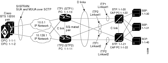
The basic A-link profile is used when a customer wants to access the SS7 network using A-links.
Figure 5-5 Basic A-link Profile (Distributed MTP3)
For pros and cons of this profile, see the "ITP-Group" section on page 2-9.
Usage
The Basic A-link Profile provides a solution that is low cost yet fully hardware and network redundant. Cost reduction is accomplished by minimizing the number of point codes that are connected to the SS7 service provider network and by connecting via A-links rather than D-links (which require more setup and maintenance).
ITP Configuration Information
This section provides a configuration example for the basic A-link profile. For additional Cisco ITP configuration information, see the Cisco ITP Configuration Guide and Command Reference at the following URL:
http://www.cisco.com/univercd/cc/td/doc/product/wireless/moblwrls/itp/25sw/itp25swi.pdf
In particular, focus on the following sections:
•
•
•
•
For other Cisco ITP example configurations, see the following URL:
ITP1 Configuration
## This is the first ITP in the ITP-Group (the first SGP in the SG).#Current configuration : 3470 bytes!version 12.2service timestamps debug datetime msecservice timestamps log datetime msecno service password-encryption!hostname ITP1!boot-start-markerboot system flash c2600-itp-mz.topsail_s_nightly_040915boot-end-marker!redundancy inter-device!enable secret 5 $1$XCoU$j0Y2wFRoks2pocHa1gHhi0enable password cisco!ipc zone defaultassociation 1no shutdownprotocol sctplocal-port 9001local-ip 10.0.1.54local-ip 10.128.1.239remote-port 9000remote-ip 10.0.1.55remote-ip 10.128.1.240!memory-size iomem 20ip subnet-zero!ip domain-name cisco.comip name-server 10.0.0.6!## Note that for the A-link (ITP-Group/Distributed MTP) configuration, the local# point code value is 1.1.1, which is the same as the BTS OPC.#cs7 variant ANSIcs7 point-code 1.1.1!controller E1 0/0framing NO-CRC4channel-group 0 timeslots 1!controller E1 0/1framing NO-CRC4channel-group 0 timeslots 1!controller E1 0/2shutdown!controller E1 0/3shutdown!interface FastEthernet0/0ip address 10.0.1.54 255.255.0.0speed autohalf-duplexno clns route-cache!interface Serial0/0:0description connect to link 0 of STP 1-1-20no ip addressencapsulation mtp2no clns route-cache!interface FastEthernet0/1ip address 10.128.1.239 255.255.0.0speed autohalf-duplexno clns route-cache!interface Serial0/1:0description connect to link 0 of STP 1-1-21no ip addressencapsulation mtp2no clns route-cache!## Unlike the D-link connection which defines a local-peer and mated-sg for# redundancy, for the Distributed MTP3 feature A-link configuration, you# define a cs7 group. This enables both ITPs in the ITP-group (or SGPs in the# SG) to communicate with each other. In this configuration you define the# IP addresses and port values for both sides of the connection.##cs7 group grp-ITP1 9004local-ip 10.0.1.54local-ip 10.128.1.239peer grp-ITP2 9003remote-ip 10.0.1.55remote-ip 10.128.1.240!## Note here that when the linksets are defined, for redundancy each linkset# has links from each ITP in the ITP-Group (or SGP in the SG).#cs7 linkset lset1chn 1.1.20link 0 grp-ITP1 Serial0/0:0link 1 grp-ITP2 Serial0/0:0!cs7 linkset lset2chn 1.1.21link 0 grp-ITP1 Serial0/1:0link 1 grp-ITP2 Serial0/1:0## Note that unlike the D-link configuration, there are no low priority routes# defined to the DPCs. This is because in the ITP-group setup the STPs view the# combination of the two ITPs is as a single entity (the two SGPs form one SG).# Because of this, there are no lower priority routes that travel across a C link# between the two ITPs like there is in the D-link configuration.#cs7 route-table systemupdate route 1.1.30 255.255.255 linkset lset1chn priority 1update route 1.1.31 255.255.255 linkset lset2chn priority 1update route 1.1.30 255.255.255 linkset lset2chn priority 1update route 1.1.31 255.255.255 linkset lset1chn priority 1update route 1.1.40 255.255.255 linkset lset2chn priority 1update route 1.1.40 255.255.255 linkset lset1chn priority 1# Routing to Capability Pt Codes of adjacent STPsupdate route 1.1.22 255.255.255 linkset lset1chn priority 1update route 1.1.22 255.255.255 linkset lset2chn priority 1!## The M3UA definition that declares local IP addresses and port ##cs7 m3ua 2905local-ip 10.0.1.54local-ip 10.128.1.239keepalive 2000!## Here as with all configurations, there are *at least* two ASPs defined for each AS# (one for the primary BTS node and one for the Secondary). In reality, there will be# at least one for each "User Part" on the BTS10200. So if you have a TCAP Service going# over SUA and ISUP traffic, you will have a total of at least four ASPs. Primary ISUP,# Secondary ISUP, Primary TCAP Service, Secondary TCAP Service.## Note that the remote port value of 11146 is configured on the BTS10200 in the# platform.cfg file (as an SGA command line argument). 2905 is the local port# value. The remote IP addresses are the BTS IP addresses. They are also obtained# through the FQDN that is an SGA command line argument.#cs7 asp PrimaryBtsIsupAsp 11146 2905 m3uaremote-ip 10.0.1.5remote-ip 10.128.1.2!cs7 asp SecondaryBtsIsupAsp 11146 2905 m3uaremote-ip 10.0.1.6remote-ip 10.128.1.3!## Note that the routing key is a very simple one. It has a routing context of 1# defined, the DPC (BTS OPC) of 1.1.1 defined and a service indicator of ISUP defined.# This means that all traffic coming from the SS7 Service Provider Network that has a# DPC of 1.1.1 and a service indicator of ISUP will be sent to either PrimaryBtsIsupAsp# or SecondaryBtsIsupAsp (depending on which one is active).## The traffic mode is always set to override (not loadshare)## In BTS release 4.4 only, there is a workaround that mandates network-appearance to be# configured with a value of 1. In BTS release 4.5, this work-around will be removed and# network-appearance should not be provisioned on the ITP.#cs7 as BtsIsupAs m3uarouting-key 1 1.1.1 si isupasp PrimaryBtsIsupAspasp SecondaryBtsIsupAsptraffic-mode overridenetwork-appearance 1!## The SUA definition that declares local IP addresses and port ##cs7 sua 14001local-ip 10.0.1.54local-ip 10.128.1.239keepalive 2000!## Here we are defining an ASPs that will process AIN related traffic. Note that# the remote port 12205 is a TSA command line parameter in platform.cfg on the BTS.# 14001 is the local port number.##cs7 asp PrimaryBtsAinAsp 12205 14001 suaremote-ip 10.0.1.5remote-ip 10.128.1.2!cs7 asp SecondaryBtsAinAsp 12205 14001 suaremote-ip 10.0.1.6remote-ip 10.128.1.3!## The following AS is defined for LNP related message flows. The routing context value# is 4, the DPC (BTS OPC) is 1.1.1, the service indicator is SCCP and the Subsystem number# is 247. This means that any message received from the SS7 Service Provider that has a# DPC of 1.1.1, a service indicator of SCCP and an SSN of 247 will be sent to either# PrimaryBtsAinAsp or SecondaryBtsAinAsp (depending on which one is active).#cs7 as BtsLnpAs suarouting-key 4 1.1.1 si sccp ssn 247asp PrimaryBtsAinAspasp SecondaryBtsAinAsptraffic-mode overrideITP2 Configuration
# This is the second ITP in the ITP-Group (the second SGP in the SG).## FOR THE ITP2 CONFIGURATION, PLEASE REFER TO THE COMMENTS THAT WERE MADE IN# THE ITP1 CONFIGURATION. IT IS PRETTY MUCH A DUPLICATE OF ITP1 EXCEPT FOR THE# ITP GROUP DEFINITION (and the comments in the link section).!Current configuration : 4054 bytes!version 12.2service timestamps debug datetime msecservice timestamps log datetime msecno service password-encryption!hostname ITP2!boot-start-markerboot system flash 2600/c2600-itp-mz.topsail_s_nightly_040915boot-end-marker!redundancy inter-device!enable secret 5 $1$B6u2$gI4fFgjOQo5XppDSWJDfI.enable password cisco!ipc zone defaultassociation 1no shutdownprotocol sctplocal-port 9000local-ip 10.0.1.55local-ip 10.128.1.240remote-port 9001remote-ip 10.0.1.54remote-ip 10.128.1.239!memory-size iomem 10ip subnet-zero!ip domain-name cisco.comip name-server 10.0.0.6!cs7 variant ANSIcs7 point-code 1.1.1!controller E1 0/0framing NO-CRC4channel-group 0 timeslots 1!controller E1 0/1framing NO-CRC4channel-group 0 timeslots 1!controller E1 0/2shutdown!controller E1 0/3shutdown!interface FastEthernet0/0ip address 10.0.1.55 255.255.0.0speed autohalf-duplexno clns route-cache!interface Serial0/0:0description connect to link 1 of STP 1-1-20no ip addressencapsulation mtp2no clns route-cache!interface FastEthernet0/1ip address 10.128.1.240 255.255.0.0speed autohalf-duplexno clns route-cache!interface Serial0/1:0description connect to link 1 of STP 1-1-21no ip addressencapsulation mtp2no clns route-cache!cs7 group grp-ITP2 9003local-ip 10.0.1.55local-ip 10.128.1.240peer grp-ITP1 9004remote-ip 10.0.1.54remote-ip 10.128.1.239!cs7 linkset lset1chn 1.1.20link 0 grp-ITP1 Serial0/0:0link 1 grp-ITP2 Serial0/0:0!cs7 linkset lset2chn 1.1.21link 0 grp-ITP1 Serial0/1:0link 1 grp-ITP2 Serial0/1:0!cs7 route-table systemupdate route 1.1.30 255.255.255 linkset lset1chn priority 1update route 1.1.31 255.255.255 linkset lset2chn priority 1update route 1.1.30 255.255.255 linkset lset2chn priority 1update route 1.1.31 255.255.255 linkset lset1chn priority 1update route 1.1.40 255.255.255 linkset lset2chn priority 1update route 1.1.40 255.255.255 linkset lset1chn priority 1# Routing to Capability Pt Codes of adjacent STPsupdate route 1.1.22 255.255.255 linkset lset1chn priority 1update route 1.1.22 255.255.255 linkset lset2chn priority 1!cs7 m3ua 2905local-ip 10.0.1.55local-ip 10.128.1.240!cs7 asp PrimaryBtsIsupAsp 11146 2905 m3uaremote-ip 10.0.1.5remote-ip 10.128.1.2!cs7 asp SecondaryBtsIsupAsp 11146 2905 m3uaremote-ip 10.0.1.6remote-ip 10.128.1.3!cs7 as BtsIsupAs m3uarouting-key 2 1.1.1 si isupasp PrimaryBtsIsupAspasp SecondaryBtsIsupAsptraffic-mode overridenetwork-appearance 1!cs7 sua 14001local-ip 10.0.1.55local-ip 10.128.1.240keepalive 2000!cs7 asp PrimaryBtsAinAsp 12205 14001 suaremote-ip 10.0.1.5remote-ip 10.128.1.2!cs7 asp SecondaryBtsAinAsp 12205 14001 suaremote-ip 10.0.1.6remote-ip 10.128.1.3!cs7 as BtsLnpAs suarouting-key 4 1.1.1 si sccp ssn 247asp PrimaryBtsAinAspasp SecondaryBtsAinAsptraffic-mode overrideCisco BTS 10200 Provisioning for the Basic A-link Profile
CA Configuration
####################################################################### CA Configuration######################################################################add ca-config type=MGCP-INIT-TERMS;value=160;datatype=integer;add ca-config type=MGCP-INIT-DURATION;value=5;datatype=integer;add ca-config type=MGCP-ICMP-PING-RETRANSMIT-DURATION;value=5;datatype=integer;add ca-config type=MGCP-ICMP-PING-RETRY-COUNT;value=5;datatype=integer;add ca-config type=MGCP-MAX-UNREACH-COUNT;value=5;datatype=integer;add ca-config type=MGCP-MAX-FAULT-COUNT;value=5;datatype=integer;add ca-config type=MGCP-ADM-RESP-TIME;value=300;datatype=integer;add ca-config type=MGCP-SIG-TOS-LOWDELAY;value=Y;datatype=boolean;add ca-config type=MGCP-SIG-TOS-PRECEDENCE;value=1;datatype=integer;add ca-config type=MGCP-SIG-TOS-RELIABILITY;value=Y;datatype=boolean;add ca-config type=MGCP-SIG-TOS-THROUGHPUT;value=Y;datatype=boolean;## CA & FS#add call-agent id=CA146; tsap-addr-sidea=hrn11ca; mgw-monitoring-enabled=N;add feature-server id=FSAIN205; tsap-addr-sidea=hrn11ca:11205; type=AIN;## Sigtran components#add user-part-variant id=ANSISS7_GR317;## Unlike the D-link solution that requires two SG definitions for each SG-GRP,# A-link (Basic Distributed MTP3) solution requires that only one SG be associated# with the SG-GRP. This is because redundancy in the A-link solution is at the SGP# level (not the SG level).#add sg id=sg1; description=Siganling gateway 1;add sg-grp id=sg-grp1; sg1-id=sg1; description=SG group 1;## Note that there are two SGP definitions per SG. This is in contrast to the# D-link solution that only allows one SGP per SG. It is at the SGP level that# the A-link/Distributed MTP3 solution provides hardware and IP network# redundancy. Note that the naming convention used in this example is# descriptive.. i.e. SGP1 of SG1 or SGP2 of SG1.#add sgp id=sg1-sgp1 ; sg-id=sg1; description=SG process 1 for sg1;add sgp id=sg1-sgp2 ; sg-id=sg1; description=SG process 2 for sg1;add opc id=opc1; point-code=1-1-1; description=OPC; point-code-type=ANSI_CHINA;add dpc id=dpc1; point-code=1-1-30; description=DPC 1; point-code-type=ANSI_CHINA;add dpc id=dpc2; point-code=1-1-31; description=DPC 2; point-code-type=ANSI_CHINA;## THE ISUP ROUTING KEYS#add routing-key id=rk1; opc-id=opc1; sg-grp-id=sg-grp1; si=ISUP; rc=1; platform-id=CA146;add call-ctrl-route id=dpc1-route1; dpc-id=dpc1; routing-key-id=rk1; si=isup; user-part-variant-id= ANSISS7_GR317add call-ctrl-route id=dpc2-route1; dpc-id=dpc2; routing-key-id=rk1; si=isup; user-part-variant-id= ANSISS7_GR317;## SCTP configuration.#add sctp-assoc-profile id=sctp-prof;## Note that the id used in the add sctp-assoc statement reflects the fact that# this is the sctp association for SGP1 of SG1.#add sctp-assoc id=sg1-sgp1-sctp; sgp-id=sg1-sgp1; sctp-assoc-profile-id=sctp-prof; platform-id=CA146; remote-port=2905; remote-tsap-addr1=10.0.1.54; remote-tsap-addr2=10.128.1.239; dscp=AF11; ip-tos-precedence=ROUTINE;add sctp-assoc id=sg2-sgp1-sctp; sgp-id=sg2-sgp1; sctp-assoc-profile-id=sctp-prof; platform-id=CA146; remote-port=2905; remote-tsap-addr1=10.0.1.55; remote-tsap-addr2=10.128.1.240; dscp=AF11; ip-tos-precedence=ROUTINE;## dial plan profile#add digman-profile id=pretrans;add digman id=pretrans; rule=1; match-string=^*; replace-string=&; match-noa=any; replace-noa=VSC;add digman id=pretrans; rule=2; match-string=^#; replace-string=&; match-noa=any; replace-noa=VSC;add digman-profile id=ani_20;add digman id=ani_20; rule=1; match-string=^20; replace-string=none;add dial-plan-profile id=dp-1; nanp-dial-plan=Y; description=NA dial plan profile; dnis-digman-id=pretrans; ani-digman-id=ani_20;## SS7 TG#add ss7-ansi-tg-profile ID=ansi-tg-prof;add trunk-grp ID=1; call_agent_id=CA146; tg_type=SS7; direction=BOTH; tg_profile_id=ansi-tg-prof; call-ctrl-route-id=dpc1-route1; dial-plan-id=dp-1; description=TG to DPC 1; MGCP_PKG_TYPE=T;add trunk-grp ID=2; call_agent_id=CA146; tg_type=SS7; direction=BOTH; tg_profile_id=ansi-tg-prof; call-ctrl-route-id=dpc2-route1; dial-plan-id=dp-1; description=TG to DPC 2; MGCP_PKG_TYPE=T;## MGW#add mgw-profile id=as5300-prof; vendor=Cisco; mgcp-hairpin-supp=n; MGCP_RSIPSTAR_SUPP=N; MGCP_TERM_INIT_LEVEL=0; RBK_ON_CONN_SUPP=N; MGCP_VERSION=MGCP_1_0; mgcp-max2-retries=3; fax-t38-camode-supp=Y; mgcp-keepalive-interval=60; mgcp-keepalive-retries=10; mgcp-t-tran=400; mgcp-max1-retries=2; mgcp-t-longtran=5; mgcp-default-pkg=NONE; MGCP_3WAY_HSHAKE_SUPP=N; mgw_type=AS5300; PC_MPTIME_SUPP=N;##MGCP_VERSION=MGCP_1_0; PC_MPTIME_SUPP=N;add mgw id=va-5350-23; tsap-addr=va-5350-23.hrndevtest.cisco.com; call-agent-id=CA146; mgw-profile-id=as5300-prof; type=TGW;## SS7 terminations and trunks#add termination prefix=S3/DS1-4/; port-start=1; port-end=31; type=trunk; mgw-id=va-5350-23;add termination prefix=S3/DS1-5/; port-start=1; port-end=31; type=trunk; mgw-id=va-5350-23;add trunk cic-start=1; cic-end=31; tgn-id=1; mgw-id=va-5350-23; termination-prefix=S3/DS1-4/; termination-port-start=1; termination-port-end=31;add trunk cic-start=1; cic-end=31; tgn-id=2; mgw-id=va-5350-23; termination-prefix=S3/DS1-5/; termination-port-start=1; termination-port-end=31;## SS7 routes, route guides and destinations#add route id=dpc1-route; tg_selection=RR; tgn1_id=1;add route id=dpc2-route; tg_selection=RR; tgn1_id=2;add route-guide id=dpc1-rg; policy-type=ROUTE; policy-id=dpc1-route;add route-guide id=dpc2-rg; policy-type=ROUTE; policy-id=dpc2-route;add destination dest-id=dpc1-dest; call-type=LOCAL; route-type=ROUTE; route-guide-id=dpc1-rg;add destination dest-id=dpc2-dest; call-type=LOCAL; route-type=ROUTE; route-guide-id=dpc2-rg;####################################### TCAP/SUA Provisioning for LNP######################################add sccp-nw id=1;NET_IND=NATIONAL;SUB_SVC=NATIONAL;HOP_COUNT=3;add subsystem-profile id=SSN_LNP1;platform_id=FSAIN205;add subsystem id=SSN_LNP1; OPC-ID=opc1; LOCAL-SSN=247;REMOTE_SSN=247; sccp-nw-id=1;SCCP_VERSION=ANS92; TCAP_VERSION=ANS92; APPLICATION_VERSION=AIN01;add routing-key id=itp-grp-rk2; opc-id=opc1; sg-grp-id=sg-grp1; si=sccp; ssn-id=SSN_LNP1; platform-id=FSAIN205; rc=4; description=Routing Key for SUA User Adaptation layer;########################################### Provisioned DPC is the STP Capabilty Pt Code##########################################add dpc id=stp_cap_pc; point-code=1-1-22; point-code-type=ANSI_CHINA; description=Capability Point Code of STPsadd feature fname=LNP; feature-server-id=FSAIN205; description=Local number portability; tdp1=COLLECTED_INFORMATION; tid1=LNP_TRIGGER; ttype1=R;add ported-office-code digit-string=301-612; in-call-agent=n;add CA-Config type=DEFAULT-LNP-SLHR-ID; datatype=string; value=slhr_lnp;add slhr-profile id=slhr_lnp;add slhr id=slhr_lnp; gtt-req=Y; tt=11; GTT_ADDR_TYPE=CDPN; GTT_ADDR=3; opc-id=opc1; dpc-id=stp_cap_pc; ssn_id=SSN_LNP1;add sccp-route opc-id=opc1; dpc-id=stp_cap_pc; rk-id=itp-grp-rk2; ssn-id=SSN_LNP1; description=LNP for opc1;add pop ID=50901; STATE=tx; COUNTRY=US; TIMEZONE=CDT; LOCAL_7D_DIALING=Y; ITP=N; ZERO_MINUS=LEC; BLOCK_EAWOPIC=Y; CNAM_OPTION=EXT_LIDB; PIC2_REQD=N; MY_LRN=4692559999; TREAT_IMS_ANONYMOUS=N; OPC_ID=opc1; ZERO_PLUS_LOCAL=N#################################################### Control network entities in-service for ANSI SS7###################################################control trunk-grp id=1; mode=forced; target-state=ins;control trunk-grp id=2; mode=forced; target-state=ins;equip trunk-termination tgn-id=1; cic=all;equip trunk-termination tgn-id=2; cic=all;control trunk-termination tgn-id=1; cic=all; target-state=INS; mode=FORCED;control trunk-termination tgn-id=2; cic=all; target-state=INS; mode=FORCED;control subsystem id=SSN_LNP1;mode=forced;target-state=uis;opc-id=opc1control sctp-assoc id=sg1-sgp1-sctp; mode=forced; target-state=INS;control sctp-assoc id=sg2-sgp1-sctp; mode=forced; target-state=INS;########################################################### Status commands###########################################################status trunk-grp id=1;#status trunk-grp id=2;#status trunk-termination tgn-id=1; cic=all;#status trunk-termination tgn-id=2; cic=all;#status sctp-assoc id=sg1-sgp1-sctp;#status sctp-assoc id=sg2-sgp1-sctp;Multiple Cisco BTS 10200 Nodes per Cisco ITP
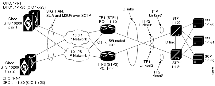
This profile is a scalable IP telephony network profile that fits the customer who wants to set up an all-IP telephony network based on Cisco BTS 10200 Softswitches and a long-term need of network expansion.
Figure 5-6 Multiple Cisco BTS 10200 Nodes per Cisco ITP
Usage
Because each Cisco BTS 10200 has just one OPC code rather than having multiple OPCs, this profile is ideal when there is a requirement for very high-capacity traffic to each OPC. A pair of high-capacity Cisco 73XX or 7507 series Cisco ITP nodes will most likely be required to provide the necessary throughput. The topology between ITPs and STPs forms a typical SS7 STP quad. GTT can be supported on the Cisco ITP.
Alternate Base Profiles
There are no alternate profiles. This profile is only available when connecting to the SS7 network via D-links.
ITP Configuration Information
The Cisco ITP configuration information is essentially the same as the configuration for the basic D-link profile provided in the "ITP Configuration Information" section. The main exception is that in this case, there is extra ASP configuration information for communicating to the second CA (BTS2). Also, there is extra information in the AS configuration section for routing to each of the Call Agents (based on DPC [Cisco BTS 10200 OPC value]). The following example shows the ASP and AS configuration elements for ITP1.
ITP1 Configuration.
############################################################################### ITP1 Configuration -## It is important to note that ITP2 will have the same ASP and AS ## configuration information that is shown below for ITP1.############################################################################## ASP configuration for BTS1 Active and Standby Nodes# For ISUP - M3UAcs7 asp PRI_ISUP_BTS1 11146 2905 m3uaremote-ip 10.0.1.5remote-ip 10.128.1.2cs7 asp SEC_ISUP_BTS1 11146 2905 m3uaremote-ip 10.0.1.6remote-ip 10.128.1.3# For TCAP/AIN - SUAcs7 asp PRI_AIN_BTS1 12205 14001 suaremote-ip 10.0.1.5remote-ip 10.128.1.2!cs7 asp SEC_AIN_BTS1 12205 14001 suaremote-ip 10.0.1.6remote-ip 10.128.1.3## AS configuration for BTS1 ## Note: In the following configuration the routing context entries are as follows:# routing context = 1, DPC(BTS OPC)=1.1.1 service indicator=ISUP# Configuring network-appearance 1 is required for release 4.4, but will not be required# in release 4.5 and beyond.cs7 as ISUP_BTS1 m3uarouting-key 1 1.1.1 si isupasp PRI_ISUP_BTS1asp SEC_ISUP_BTS1traffic-mode overridenetwork-appearance 1cs7 as LNP_BTS1 suarouting-key 4 1.1.1 si sccp ssn 247asp PRI_AIN_BTS1asp SEC_AIN_BTS1traffic-mode override## ASP configuration for BTS2 Active and Standby Nodes## For ISUP - M3UAcs7 asp PRI_ISUP_BTS2 11146 2905 m3uaremote-ip 10.0.1.7remote-ip 10.128.1.4cs7 asp SEC_ISUP_BTS2 11146 2905 m3uaremote-ip 10.0.1.8remote-ip 10.128.1.5# For TCAP/AIN - SUAcs7 asp PRI_AIN_BTS2 12205 14001 suaremote-ip 10.0.1.7remote-ip 10.128.1.4!cs7 asp SEC_AIN_BTS2 12205 14001 suaremote-ip 10.0.1.8remote-ip 10.128.1.5## AS configuration for BTS2 # Note that the DPC value changes to 1.1.2 for sending messages to BTS2cs7 as ISUP_BTS2 m3uarouting-key 2 1.1.2 si isupasp PRI_ISUP_BTS2asp SEC_ISUP_BTS2traffic-mode overridenetwork-appearance 1cs7 as LNP_BTS2 suarouting-key 5 1.1.2 si sccp ssn 247asp PRI_AIN_BTS2asp SEC_AIN_BTS2traffic-mode overrideCisco BTS 10200 Provisioning Information
The Cisco BTS 10200 provisioning for this profile is essentially the same as the basic D-link profile in the "Cisco BTS 10200 Provisioning for the Basic D-link Profile" section, except that there is a second Cisco BTS 10200 provisioning script that is needed for BTS2. It is shown here:
CA Configuration
########################################################################## CA Configuration#########################################################################add ca-config type=MGCP-INIT-TERMS;value=160;datatype=integer;add ca-config type=MGCP-INIT-DURATION;value=5;datatype=integer;add ca-config type=MGCP-ICMP-PING-RETRANSMIT-DURATION;value=5;datatype=integer;add ca-config type=MGCP-ICMP-PING-RETRY-COUNT;value=5;datatype=integer;add ca-config type=MGCP-MAX-UNREACH-COUNT;value=5;datatype=integer;add ca-config type=MGCP-MAX-FAULT-COUNT;value=5;datatype=integer;add ca-config type=MGCP-ADM-RESP-TIME;value=300;datatype=integer;add ca-config type=MGCP-SIG-TOS-LOWDELAY;value=Y;datatype=boolean;add ca-config type=MGCP-SIG-TOS-PRECEDENCE;value=1;datatype=integer;add ca-config type=MGCP-SIG-TOS-RELIABILITY;value=Y;datatype=boolean;add ca-config type=MGCP-SIG-TOS-THROUGHPUT;value=Y;datatype=boolean;## CA & FS## Note that the ids: CA147 and FSAIN206 are different than on BTS1.#add call-agent id=CA147; tsap-addr-sidea=hrn11ca; mgw-monitoring-enabled=N;add feature-server id=FSAIN206; tsap-addr-sidea=hrn11ca:11205; type=AIN;## Sigtran components#add user-part-variant id=ANSISS7_GR317;add sg id=sg1; description=Signaling gateway 1;add sg id=sg2; description=Signaling gateway 2;add sg-grp id=sg-grp1; sg1-id=sg1; sg2-id=sg2 description=SG group 1;add sgp id=sg1-sgp1 ; sg-id=sg1; description=SG process 1 for sg1;add sgp id=sg2-sgp1 ; sg-id=sg2; description=SG process 1 for sg2;## Note that the OPC value for BTS2 is 1-1-2#add opc id=opc1; point-code=1-1-2; description=OPC; point-code-type=ANSI_CHINA;add dpc id=dpc1; point-code=1-1-30; description=DPC 1; point-code-type=ANSI_CHINA;add dpc id=dpc2; point-code=1-1-31; description=DPC 2; point-code-type=ANSI_CHINA;## THE ISUP ROUTING KEYS## Note that a unique rc value was needed when defining the routing-key. It must match# the rc value that is defined in the associated AS/routing-key definition in the ITPs.# This routing key has a different OPC value than defined for BTS1.#add routing-key id=rk1; opc-id=opc1; sg-grp-id=sg-grp1; si=ISUP; rc=2; platform-id=CA147;add call-ctrl-route id=dpc1-route1; dpc-id=dpc1; routing-key-id=rk1; si=isup; user-part-variant-id= ANSISS7_GR317add call-ctrl-route id=dpc2-route1; dpc-id=dpc2; routing-key-id=rk1; si=isup; user-part-variant-id= ANSISS7_GR317;add sctp-assoc-profile id=sctp-prof;## THE SCTP ASSOCIATIONS#add sctp-assoc id=sg1-sgp1-sctp; sgp-id=sg1-sgp1; sctp-assoc-profile-id=sctp-prof; platform-id=CA147; remote-port=2905; remote-tsap-addr1=10.0.1.54; remote-tsap-addr2=10.128.1.239; dscp=AF11; ip-tos-precedence=ROUTINE;add sctp-assoc id=sg2-sgp1-sctp; sgp-id=sg2-sgp1; sctp-assoc-profile-id=sctp-prof; platform-id=CA147; remote-port=2905; remote-tsap-addr1=10.0.1.55; remote-tsap-addr2=10.128.1.240; dscp=AF11; ip-tos-precedence=ROUTINE;## dial plan profile#add digman-profile id=pretrans;add digman id=pretrans; rule=1; match-string=^*; replace-string=&; match-noa=any; replace-noa=VSC;add digman id=pretrans; rule=2; match-string=^#; replace-string=&; match-noa=any; replace-noa=VSC;add digman-profile id=ani_20;add digman id=ani_20; rule=1; match-string=^20; replace-string=none;add dial-plan-profile id=dp-1; nanp-dial-plan=Y; description=NA dial plan profile; dnis-digman-id=pretrans; ani-digman-id=ani_20;## SS7 TG#add ss7-ansi-tg-profile ID=ansi-tg-prof;add trunk-grp ID=1; call_agent_id=CA147; tg_type=SS7; direction=BOTH; tg_profile_id=ansi-tg-prof; call-ctrl-route-id=dpc1-route1; dial-plan-id=dp-1; description=TG to DPC 1; MGCP_PKG_TYPE=T;add trunk-grp ID=2; call_agent_id=CA147; tg_type=SS7; direction=BOTH; tg_profile_id=ansi-tg-prof; call-ctrl-route-id=dpc2-route1; dial-plan-id=dp-1; description=TG to DPC 2; MGCP_PKG_TYPE=T;## MGW#add mgw-profile id=as5300-prof; vendor=Cisco; mgcp-hairpin-supp=n; MGCP_RSIPSTAR_SUPP=N; MGCP_TERM_INIT_LEVEL=0; RBK_ON_CONN_SUPP=N; MGCP_VERSION=MGCP_1_0; mgcp-max2-retries=3; fax-t38-camode-supp=Y; mgcp-keepalive-interval=60; mgcp-keepalive-retries=10; mgcp-t-tran=400; mgcp-max1-retries=2; mgcp-t-longtran=5; mgcp-default-pkg=NONE; MGCP_3WAY_HSHAKE_SUPP=N; mgw_type=AS5300; PC_MPTIME_SUPP=N;##MGCP_VERSION=MGCP_1_0; PC_MPTIME_SUPP=N;add mgw id=va-5350-23; tsap-addr=va-5350-23.hrndevtest.cisco.com; call-agent-id=CA147; mgw-profile-id=as5300-prof; type=TGW;## SS7 terminations and trunks#add termination prefix=S3/DS1-4/; port-start=1; port-end=31; type=trunk; mgw-id=va-5350-23;add termination prefix=S3/DS1-5/; port-start=1; port-end=31; type=trunk; mgw-id=va-5350-23;add trunk cic-start=1; cic-end=31; tgn-id=1; mgw-id=va-5350-23; termination-prefix=S3/DS1-4/; termination-port-start=1; termination-port-end=31;add trunk cic-start=1; cic-end=31; tgn-id=2; mgw-id=va-5350-23; termination-prefix=S3/DS1-5/; termination-port-start=1; termination-port-end=31;## SS7 routes, route guides and destinations#add route id=dpc1-route; tg_selection=RR; tgn1_id=1;add route id=dpc2-route; tg_selection=RR; tgn1_id=2;add route-guide id=dpc1-rg; policy-type=ROUTE; policy-id=dpc1-route;add route-guide id=dpc2-rg; policy-type=ROUTE; policy-id=dpc2-route;add destination dest-id=dpc1-dest; call-type=LOCAL; route-type=ROUTE; route-guide-id=dpc1-rg;add destination dest-id=dpc2-dest; call-type=LOCAL; route-type=ROUTE; route-guide-id=dpc2-rg;####################################### TCAP/SUA Provisioning for LNP######################################add sccp-nw id=1;NET_IND=NATIONAL;SUB_SVC=NATIONAL;HOP_COUNT=3;add subsystem-profile id=SSN_LNP1;platform_id=FSAIN206;add subsystem id=SSN_LNP1; OPC-ID=opc1; LOCAL-SSN=247;REMOTE_SSN=247; sccp-nw-id=1;SCCP_VERSION=ANS92; TCAP_VERSION=ANS92; APPLICATION_VERSION=AIN01;# Note this routing key differs from the one on BTS1add routing-key id=itp-grp-rk2; opc-id=opc1; sg-grp-id=sg-grp1; si=sccp; ssn-id=SSN_LNP1; platform-id=FSAIN206; rc=5; description=Routing Key for SUA User Adaptation layer;########################################### Provisioned DPC is the STP Capabilty Pt Code##########################################add dpc id=stp_cap_pc; point-code=1-1-22; point-code-type=ANSI_CHINA; description=Capability Point Code of STPsadd feature fname=LNP; feature-server-id=FSAIN206; description=Local number portability; tdp1=COLLECTED_INFORMATION; tid1=LNP_TRIGGER; ttype1=R;add ported-office-code digit-string=301-612; in-call-agent=n;add CA-Config type=DEFAULT-LNP-SLHR-ID; datatype=string; value=slhr_lnp;add slhr-profile id=slhr_lnp;add slhr id=slhr_lnp; gtt-req=Y; tt=11; GTT_ADDR_TYPE=CDPN; GTT_ADDR=3; opc-id=opc1; dpc-id=stp_cap_pc; ssn_id=SSN_LNP1;add sccp-route opc-id=opc1; dpc-id=stp_cap_pc; rk-id=itp-grp-rk2; ssn-id=SSN_LNP1; description=LNP for opc1;add pop ID=50901; STATE=tx; COUNTRY=US; TIMEZONE=CDT; LOCAL_7D_DIALING=Y; ITP=N; ZERO_MINUS=LEC; BLOCK_EAWOPIC=Y; CNAM_OPTION=EXT_LIDB; PIC2_REQD=N; MY_LRN=4692559999; TREAT_IMS_ANONYMOUS=N; OPC_ID=opc1; ZERO_PLUS_LOCAL=NMultiple Cisco BTS 10200 OPCs with D-Link Profile
This profile, based on the D-link profile, fits the customer who wants to emulate multiple legacy SS7 switches with one high-capacity Cisco BTS 10200 Softswitch.
Figure 5-7 Multiple Cisco BTS 10200 OPCs with D-link Profile
Alternate Base Profiles
Although this profile is based on the D-link profile, a similar A-link profile can be implemented. However, it is not a very desirable method for achieving multiple OPCs on the Cisco BTS 10200 because it requires a separate ITP-Group for each OPC.
ITP Configuration Information
The Cisco ITP configuration is essentially the same as the configuration for the D-link profile in the "ITP Configuration Information" section. The only difference is that there is an extra AS configuration information for the added OPC on BTS1. This additional AS configuration information is shown here:
cs7 as BtsIsupAs2 m3uarouting-key 2 1.1.2 si isupasp PrimaryBtsIsupAspasp SecondaryBtsIsupAsptraffic-mode overridenetwork-appearance 1cs7 as BtsLnpAs2 suarouting-key 5 1.1.2 si sccp ssn 247asp PrimaryBtsAinAspasp SecondaryBtsAinAsptraffic-mode overrideCisco BTS 10200 Provisioning Information
The Cisco BTS 10200 Provisioning information is essentially the same as the basic D-link configuration in the "Cisco BTS 10200 Provisioning for the Basic D-link Profile" section with some added objects based on the OPC 1.1.2. The Cisco BTS 10200 configuration is shown here.
########################################################################## CA Configuration#########################################################################add ca-config type=MGCP-INIT-TERMS;value=160;datatype=integer;add ca-config type=MGCP-INIT-DURATION;value=5;datatype=integer;add ca-config type=MGCP-ICMP-PING-RETRANSMIT-DURATION;value=5;datatype=integer;add ca-config type=MGCP-ICMP-PING-RETRY-COUNT;value=5;datatype=integer;add ca-config type=MGCP-MAX-UNREACH-COUNT;value=5;datatype=integer;add ca-config type=MGCP-MAX-FAULT-COUNT;value=5;datatype=integer;add ca-config type=MGCP-ADM-RESP-TIME;value=300;datatype=integer;add ca-config type=MGCP-SIG-TOS-LOWDELAY;value=Y;datatype=boolean;add ca-config type=MGCP-SIG-TOS-PRECEDENCE;value=1;datatype=integer;add ca-config type=MGCP-SIG-TOS-RELIABILITY;value=Y;datatype=boolean;add ca-config type=MGCP-SIG-TOS-THROUGHPUT;value=Y;datatype=boolean;## CA & FS#add call-agent id=CA146; tsap-addr-sidea=hrn11ca; mgw-monitoring-enabled=N;add feature-server id=FSAIN205; tsap-addr-sidea=hrn11ca:11205; type=AIN;## Sigtran / SS7 components#add user-part-variant id=ANSISS7_GR317;add sg id=sg1; description=Signaling gateway 1;add sg id=sg2; description=Signaling gateway 2;add sg-grp id=sg-grp1; sg1-id=sg1; sg2-id=sg2 description=SG group 1;add sgp id=sg1-sgp1 ; sg-id=sg1; description=SG process 1 for sg1;add sgp id=sg2-sgp1 ; sg-id=sg2; description=SG process 1 for sg2;add opc id=opc1; point-code=1-1-1; description=OPC1; point-code-type=ANSI_CHINA;# The Second OPCadd opc id=opc2; point-code=1-1-2; description=OPC2; point-code-type=ANSI_CHINA;add dpc id=dpc1; point-code=1-1-30; description=DPC 1; point-code-type=ANSI_CHINA;add dpc id=dpc2; point-code=1-1-31; description=DPC 2; point-code-type=ANSI_CHINA;# THE ISUP ROUTING KEYSadd routing-key id=rk1; opc-id=opc1; sg-grp-id=sg-grp1; si=ISUP; rc=1; platform-id=CA146;# The new ISUP routing key added for OPC2add routing-key id=rk2; opc-id=opc2; sg-grp-id=sg-grp1; si=ISUP; rc=2; platform-id=CA146;add call-ctrl-route id=dpc1-route1; dpc-id=dpc1; routing-key-id=rk1; si=isup; user-part-variant-id= ANSISS7_GR317add call-ctrl-route id=dpc2-route1; dpc-id=dpc2; routing-key-id=rk1; si=isup; user-part-variant-id= ANSISS7_GR317;# Two New Routes added for OPC2add call-ctrl-route id=dpc1-route2; dpc-id=dpc1; routing-key-id=rk2; si=isup; user-part-variant-id= ANSISS7_GR317add call-ctrl-route id=dpc2-route2; dpc-id=dpc2; routing-key-id=rk2; si=isup; user-part-variant-id= ANSISS7_GR317;add sctp-assoc-profile id=sctp-prof;# THE SCTP ASSOCIATIONSadd sctp-assoc id=sg1-sgp1-sctp; sgp-id=sg1-sgp1; sctp-assoc-profile-id=sctp-prof; platform-id=CA146; remote-port=2905; remote-tsap-addr1=10.0.1.54; remote-tsap-addr2=10.128.1.239; dscp=AF11; ip-tos-precedence=ROUTINE;add sctp-assoc id=sg2-sgp1-sctp; sgp-id=sg2-sgp1; sctp-assoc-profile-id=sctp-prof; platform-id=CA146; remote-port=2905; remote-tsap-addr1=10.0.1.55; remote-tsap-addr2=10.128.1.240; dscp=AF11; ip-tos-precedence=ROUTINE;## dial plan profile#add digman-profile id=pretrans;add digman id=pretrans; rule=1; match-string=^*; replace-string=&; match-noa=any; replace-noa=VSC;add digman id=pretrans; rule=2; match-string=^#; replace-string=&; match-noa=any; replace-noa=VSC;add digman-profile id=ani_20;add digman id=ani_20; rule=1; match-string=^20; replace-string=none;add dial-plan-profile id=dp-1; nanp-dial-plan=Y; description=NA dial plan profile; dnis-digman-id=pretrans; ani-digman-id=ani_20;## SS7 TG#add ss7-ansi-tg-profile ID=ansi-tg-prof;add trunk-grp ID=1; call_agent_id=CA146; tg_type=SS7; direction=BOTH; tg_profile_id=ansi-tg-prof; call-ctrl-route-id=dpc1-route1; dial-plan-id=dp-1; description=TG to DPC 1; MGCP_PKG_TYPE=T;add trunk-grp ID=2; call_agent_id=CA146; tg_type=SS7; direction=BOTH; tg_profile_id=ansi-tg-prof; call-ctrl-route-id=dpc2-route1; dial-plan-id=dp-1; description=TG to DPC 2; MGCP_PKG_TYPE=T;# Two new trunk-groups added for OPC2add trunk-grp ID=3; call_agent_id=CA146; tg_type=SS7; direction=BOTH; tg_profile_id=ansi-tg-prof; call-ctrl-route-id=dpc1-route2; dial-plan-id=dp-1; description=TG2 to DPC 1; MGCP_PKG_TYPE=T;add trunk-grp ID=4; call_agent_id=CA146; tg_type=SS7; direction=BOTH; tg_profile_id=ansi-tg-prof; call-ctrl-route-id=dpc2-route2; dial-plan-id=dp-1; description=TG2 to DPC 2; MGCP_PKG_TYPE=T;## MGW#add mgw-profile id=as5300-prof; vendor=Cisco; mgcp-hairpin-supp=n; MGCP_RSIPSTAR_SUPP=N; MGCP_TERM_INIT_LEVEL=0; RBK_ON_CONN_SUPP=N; MGCP_VERSION=MGCP_1_0; mgcp-max2-retries=3; fax-t38-camode-supp=Y; mgcp-keepalive-interval=60; mgcp-keepalive-retries=10; mgcp-t-tran=400; mgcp-max1-retries=2; mgcp-t-longtran=5; mgcp-default-pkg=NONE; MGCP_3WAY_HSHAKE_SUPP=N; mgw_type=AS5300; PC_MPTIME_SUPP=N;##MGCP_VERSION=MGCP_1_0; PC_MPTIME_SUPP=N;add mgw id=va-5350-23; tsap-addr=va-5350-23.hrndevtest.cisco.com; call-agent-id=CA146; mgw-profile-id=as5300-prof; type=TGW;## SS7 terminations and trunks#add termination prefix=S3/DS1-4/; port-start=1; port-end=31; type=trunk; mgw-id=va-5350-23;add termination prefix=S3/DS1-5/; port-start=1; port-end=31; type=trunk; mgw-id=va-5350-23;add trunk cic-start=1; cic-end=31; tgn-id=1; mgw-id=va-5350-23; termination-prefix=S3/DS1-4/; termination-port-start=1; termination-port-end=31;add trunk cic-start=1; cic-end=31; tgn-id=2; mgw-id=va-5350-23; termination-prefix=S3/DS1-5/; termination-port-start=1; termination-port-end=31;# New termination and trunk information for OPC2add termination prefix=S3/DS1-6/; port-start=1; port-end=31; type=trunk; mgw-id=va-5350-23;add termination prefix=S3/DS1-7/; port-start=1; port-end=31; type=trunk; mgw-id=va-5350-23;add trunk cic-start=1; cic-end=31; tgn-id=3; mgw-id=va-5350-23; termination-prefix=S3/DS1-6/; termination-port-start=1; termination-port-end=31;add trunk cic-start=1; cic-end=31; tgn-id=4; mgw-id=va-5350-23; termination-prefix=S3/DS1-7/; termination-port-start=1; termination-port-end=31;## SS7 routes, route guides and destinations#add route id=dpc1-route; tg_selection=RR; tgn1_id=1;add route id=dpc2-route; tg_selection=RR; tgn1_id=2;add route-guide id=dpc1-rg; policy-type=ROUTE; policy-id=dpc1-route;add route-guide id=dpc2-rg; policy-type=ROUTE; policy-id=dpc2-route;add destination dest-id=dpc1-dest; call-type=LOCAL; route-type=ROUTE; route-guide-id=dpc1-rg;add destination dest-id=dpc2-dest; call-type=LOCAL; route-type=ROUTE; route-guide-id=dpc2-rg;# New route, route guide and destination information for OPC2add route id=dpc1-route2; tg_selection=RR; tgn1_id=3;add route id=dpc2-route2; tg_selection=RR; tgn1_id=4;add route-guide id=dpc1-rg2; policy-type=ROUTE; policy-id=dpc1-route2;add route-guide id=dpc2-rg2; policy-type=ROUTE; policy-id=dpc2-route2;add destination dest-id=dpc1-dest2; call-type=LOCAL; route-type=ROUTE; route-guide-id=dpc1-rg2;add destination dest-id=dpc2-dest2; call-type=LOCAL; route-type=ROUTE; route-guide-id=dpc2-rg2;####################################### TCAP/SUA Provisioning for LNP######################################add sccp-nw id=1;NET_IND=NATIONAL;SUB_SVC=NATIONAL;HOP_COUNT=3;add subsystem-profile id=SSN_LNP1;platform_id=FSAIN205;add subsystem id=SSN_LNP1; OPC-ID=opc1; LOCAL-SSN=247;REMOTE_SSN=247; sccp-nw-id=1;SCCP_VERSION=ANS92; TCAP_VERSION=ANS92; APPLICATION_VERSION=AIN01;# New subsystem ID for OPC2add subsystem id=SSN_LNP2; OPC-ID=opc2; LOCAL-SSN=247;REMOTE_SSN=247; sccp-nw-id=1;SCCP_VERSION=ANS92; TCAP_VERSION=ANS92; APPLICATION_VERSION=AIN01;add routing-key id=itp-grp-rk2; opc-id=opc1; sg-grp-id=sg-grp1; si=sccp; ssn-id=SSN_LNP1; platform-id=FSAIN205; rc=4; description=Routing Key for SUA User Adaptation layer;# New routing-key for OPC2add routing-key id=itp-grp-rk3; opc-id=opc2; sg-grp-id=sg-grp1; si=sccp; ssn-id=SSN_LNP1; platform-id=FSAIN205; rc=5; description=Routing Key for SUA User Adaptation layer;########################################### Provisioned DPC is the STP Capabilty Pt Code##########################################add dpc id=stp_cap_pc; point-code=1-1-22; point-code-type=ANSI_CHINA; description=Capability Point Code of STPsadd feature fname=LNP; feature-server-id=FSAIN205; description=Local number portability; tdp1=COLLECTED_INFORMATION; tid1=LNP_TRIGGER; ttype1=R;add ported-office-code digit-string=301-612; in-call-agent=n;add CA-Config type=DEFAULT-LNP-SLHR-ID; datatype=string; value=slhr_lnp;add slhr-profile id=slhr_lnp;add slhr id=slhr_lnp; gtt-req=Y; tt=11; GTT_ADDR_TYPE=CDPN; GTT_ADDR=3; opc-id=opc1; dpc-id=stp_cap_pc; ssn_id=SSN_LNP1;# New slhr for OPC2add slhr id=slhr_lnp1; gtt-req=Y; tt=11; GTT_ADDR_TYPE=CDPN; GTT_ADDR=3; opc-id=opc2; dpc-id=stp_cap_pc; ssn_id=SSN_LNP1;add sccp-route opc-id=opc1; dpc-id=stp_cap_pc; rk-id=itp-grp-rk2; ssn-id=SSN_LNP1; description=LNP for opc1;# New sccp-route for OPC2add sccp-route opc-id=opc2; dpc-id=stp_cap_pc; rk-id=itp-grp-rk3; ssn-id=SSN_LNP1; description=LNP for opc2;add pop ID=50901; STATE=tx; COUNTRY=US; TIMEZONE=CDT; LOCAL_7D_DIALING=Y; ITP=N; ZERO_MINUS=LEC; BLOCK_EAWOPIC=Y; CNAM_OPTION=EXT_LIDB; PIC2_REQD=N; MY_LRN=4692559999; TREAT_IMS_ANONYMOUS=N; OPC_ID=opc1; ZERO_PLUS_LOCAL=N# New pop for OPC2add pop ID=50902; STATE=tx; COUNTRY=US; TIMEZONE=CDT; LOCAL_7D_DIALING=Y; ITP=N; ZERO_MINUS=LEC; BLOCK_EAWOPIC=Y; CNAM_OPTION=EXT_LIDB; PIC2_REQD=N; MY_LRN=4692559991; TREAT_IMS_ANONYMOUS=N; OPC_ID=opc2; ZERO_PLUS_LOCAL=NConnecting with Multiple SS7 Networks via A-links
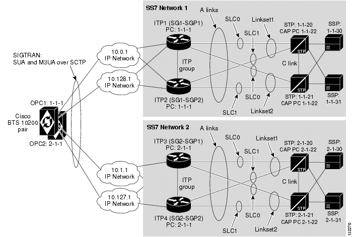
This profile ( Figure 5-8) fits the customer who operates in two different service provider's networks and uses only a single point code for each of those networks. Note that OPC 1-1-1 communicates with SS7 Network 1 and OPC 2-1-1 communicates with SS7 Network 2.
Figure 5-8 Communicating with Multiple SS7 Networks via A-links
Limitations
The A-link profile requires an ITP-Group (two Cisco ITP nodes) per Cisco BTS 10200 OPC.
Alternate Base Profiles
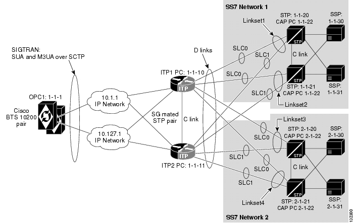
A profile based on the D-link profile is also an option (see Figure 5-9). It is generally preferred over the A-link based profile if there are more than two OPCs on the Cisco BTS 10200.
ITP Configuration Information
The Cisco ITP configuration for the A-links to multiple SS7 Networks profile is essentially a doubling of the basic A-link configuration shown in the "ITP Configuration Information" section. ITP1 and ITP2 are configured exactly the same as in that section. The configurations for ITP3 and ITP4 are very similar, except that they have different IP address, point code, and routing key information added in the respective configuration entries to match the values shown in Figure 5-8.
Figure 5-9 Communicating to Multiple SS7 Networks via D-links
Cisco BTS 10200 Provisioning Information
The provisioning information for the A-links to multiple SS7 networks is the same as the basic A-link provisioning in the "Cisco BTS 10200 Provisioning for the Basic A-link Profile" section except there is double SS7-related information. The provisioning script is as follows:
####################################################################### CA Configuration######################################################################add ca-config type=MGCP-INIT-TERMS;value=160;datatype=integer;add ca-config type=MGCP-INIT-DURATION;value=5;datatype=integer;add ca-config type=MGCP-ICMP-PING-RETRANSMIT-DURATION;value=5;datatype=integer;add ca-config type=MGCP-ICMP-PING-RETRY-COUNT;value=5;datatype=integer;add ca-config type=MGCP-MAX-UNREACH-COUNT;value=5;datatype=integer;add ca-config type=MGCP-MAX-FAULT-COUNT;value=5;datatype=integer;add ca-config type=MGCP-ADM-RESP-TIME;value=300;datatype=integer;add ca-config type=MGCP-SIG-TOS-LOWDELAY;value=Y;datatype=boolean;add ca-config type=MGCP-SIG-TOS-PRECEDENCE;value=1;datatype=integer;add ca-config type=MGCP-SIG-TOS-RELIABILITY;value=Y;datatype=boolean;add ca-config type=MGCP-SIG-TOS-THROUGHPUT;value=Y;datatype=boolean;## CA & FS#add call-agent id=CA146; tsap-addr-sidea=hrn11ca; mgw-monitoring-enabled=N;add feature-server id=FSAIN205; tsap-addr-sidea=hrn11ca:11205; type=AIN;## Sigtran components#add sg id=sg1; description=Signaling gateway 1;add sg-grp id=sg-grp1; sg1-id=sg1; description=SG group 1;add sgp id=sg1-sgp1 ; sg-id=sg1; description=SG process 1 for sg1;add sgp id=sg1-sgp2 ; sg-id=sg1; description=SG process 2 for sg1;add sctp-assoc-profile id=sctp-prof;add sctp-assoc id=sg1-sgp1-sctp; sgp-id=sg1-sgp1; sctp-assoc-profile-id=sctp-prof; platform-id=CA146; remote-port=2905; remote-tsap-addr1=10.0.1.54; remote-tsap-addr2=10.128.1.239; dscp=AF11; ip-tos-precedence=ROUTINE;add sctp-assoc id=sg2-sgp1-sctp; sgp-id=sg2-sgp1; sctp-assoc-profile-id=sctp-prof; platform-id=CA146; remote-port=2905; remote-tsap-addr1=10.0.1.55; remote-tsap-addr2=10.128.1.240; dscp=AF11; ip-tos-precedence=ROUTINE;## Added Sigtran components for SS7 Network 2#add sg id=sg2; description=Signaling gateway 2;add sg-grp id=sg-grp2; sg1-id=sg2; description=SG group 2;add sgp id=sg2-sgp1 ; sg-id=sg2; description=SG process 1 for sg2;add sgp id=sg2-sgp2 ; sg-id=sg2; description=SG process 2 for sg2;add sctp-assoc id=sg1-sgp1-sctp; sgp-id=sg1-sgp1; sctp-assoc-profile-id=sctp-prof; platform-id=CA146; remote-port=2905; remote-tsap-addr1=10.1.1.54; remote-tsap-addr2=10.127.1.239; dscp=AF11; ip-tos-precedence=ROUTINE;add sctp-assoc id=sg2-sgp1-sctp; sgp-id=sg2-sgp1; sctp-assoc-profile-id=sctp-prof; platform-id=CA146; remote-port=2905; remote-tsap-addr1=10.1.1.55; remote-tsap-addr2=10.127.1.240; dscp=AF11; ip-tos-precedence=ROUTINE;## SS7 Related Objects#add user-part-variant id=ANSISS7_GR317;add opc id=opc1; point-code=1-1-1; description=OPC1; point-code-type=ANSI_CHINA;add dpc id=dpc1; point-code=1-1-30; description=DPC 1-1-30; point-code-type=ANSI_CHINA;add dpc id=dpc2; point-code=1-1-31; description=DPC 1-1-31; point-code-type=ANSI_CHINA;add routing-key id=rk1; opc-id=opc1; sg-grp-id=sg-grp1; si=ISUP; rc=1; platform-id=CA146;add call-ctrl-route id=dpc1-route1; dpc-id=dpc1; routing-key-id=rk1; si=isup; user-part-variant-id= ANSISS7_GR317add call-ctrl-route id=dpc2-route1; dpc-id=dpc2; routing-key-id=rk1; si=isup; user-part-variant-id= ANSISS7_GR317;## Added SS7 components for SS7 Network 2#add opc id=opc2; point-code=2-1-1; description=OPC2; point-code-type=ANSI_CHINA;add dpc id=dpc3; point-code=2-1-30; description=DPC 2-1-30; point-code-type=ANSI_CHINA;add dpc id=dpc4; point-code=2-1-31; description=DPC 2-1-31; point-code-type=ANSI_CHINA;add routing-key id=rk2; opc-id=opc2; sg-grp-id=sg-grp2; si=ISUP; rc=2; platform-id=CA146;add call-ctrl-route id=dpc3-route1; dpc-id=dpc3; routing-key-id=rk2; si=isup; user-part-variant-id= ANSISS7_GR317add call-ctrl-route id=dpc4-route1; dpc-id=dpc4; routing-key-id=rk2; si=isup; user-part-variant-id= ANSISS7_GR317;## dial plan profile#add digman-profile id=pretrans;add digman id=pretrans; rule=1; match-string=^*; replace-string=&; match-noa=any; replace-noa=VSC;add digman id=pretrans; rule=2; match-string=^#; replace-string=&; match-noa=any; replace-noa=VSC;add digman-profile id=ani_20;add digman id=ani_20; rule=1; match-string=^20; replace-string=none;add dial-plan-profile id=dp-1; nanp-dial-plan=Y; description=NA dial plan profile; dnis-digman-id=pretrans; ani-digman-id=ani_20;## SS7 TG#add ss7-ansi-tg-profile ID=ansi-tg-prof;add trunk-grp ID=1; call_agent_id=CA146; tg_type=SS7; direction=BOTH; tg_profile_id=ansi-tg-prof; call-ctrl-route-id=dpc1-route1; dial-plan-id=dp-1; description=TG to DPC 1; MGCP_PKG_TYPE=T;add trunk-grp ID=2; call_agent_id=CA146; tg_type=SS7; direction=BOTH; tg_profile_id=ansi-tg-prof; call-ctrl-route-id=dpc2-route1; dial-plan-id=dp-1; description=TG to DPC 2; MGCP_PKG_TYPE=T;## Additional TG Information for SS7 Network 2#add trunk-grp ID=3; call_agent_id=CA146; tg_type=SS7; direction=BOTH; tg_profile_id=ansi-tg-prof; call-ctrl-route-id=dpc3-route1; dial-plan-id=dp-1; description=TG to DPC 3; MGCP_PKG_TYPE=T;add trunk-grp ID=4; call_agent_id=CA146; tg_type=SS7; direction=BOTH; tg_profile_id=ansi-tg-prof; call-ctrl-route-id=dpc4-route1; dial-plan-id=dp-1; description=TG to DPC 4; MGCP_PKG_TYPE=T;## MGW#add mgw-profile id=as5300-prof; vendor=Cisco; mgcp-hairpin-supp=n; MGCP_RSIPSTAR_SUPP=N; MGCP_TERM_INIT_LEVEL=0; RBK_ON_CONN_SUPP=N; MGCP_VERSION=MGCP_1_0; mgcp-max2-retries=3; fax-t38-camode-supp=Y; mgcp-keepalive-interval=60; mgcp-keepalive-retries=10; mgcp-t-tran=400; mgcp-max1-retries=2; mgcp-t-longtran=5; mgcp-default-pkg=NONE; MGCP_3WAY_HSHAKE_SUPP=N; mgw_type=AS5300; PC_MPTIME_SUPP=N; MGCP_VERSION=MGCP_1_0; PC_MPTIME_SUPP=N;add mgw id=va-5350-23; tsap-addr=va-5350-23.hrndevtest.cisco.com; call-agent-id=CA146; mgw-profile-id=as5300-prof; type=TGW;## Additional MGW Information for SS7 Network 2#add mgw id=va-5350-24; tsap-addr=va-5350-24.hrndevtest.cisco.com; call-agent-id=CA146; mgw-profile-id=as5300-prof; type=TGW;## SS7 terminations and trunks#add termination prefix=S3/DS1-4/; port-start=1; port-end=31; type=trunk; mgw-id=va-5350-23;add termination prefix=S3/DS1-5/; port-start=1; port-end=31; type=trunk; mgw-id=va-5350-23;add trunk cic-start=1; cic-end=31; tgn-id=1; mgw-id=va-5350-23; termination-prefix=S3/DS1-4/; termination-port-start=1; termination-port-end=31;add trunk cic-start=1; cic-end=31; tgn-id=2; mgw-id=va-5350-23; termination-prefix=S3/DS1-5/; termination-port-start=1; termination-port-end=31;## Additional SS7 termination and trunk info for SS7 Network 2#add termination prefix=S3/DS1-4/; port-start=1; port-end=31; type=trunk; mgw-id=va-5350-24;add termination prefix=S3/DS1-5/; port-start=1; port-end=31; type=trunk; mgw-id=va-5350-24;add trunk cic-start=1; cic-end=31; tgn-id=3; mgw-id=va-5350-24; termination-prefix=S3/DS1-4/; termination-port-start=1; termination-port-end=31;add trunk cic-start=1; cic-end=31; tgn-id=4; mgw-id=va-5350-24; termination-prefix=S3/DS1-5/; termination-port-start=1; termination-port-end=31;## SS7 routes, route guides and destinations#add route id=dpc1-route; tg_selection=RR; tgn1_id=1;add route id=dpc2-route; tg_selection=RR; tgn1_id=2;add route-guide id=dpc1-rg; policy-type=ROUTE; policy-id=dpc1-route;add route-guide id=dpc2-rg; policy-type=ROUTE; policy-id=dpc2-route;add destination dest-id=dpc1-dest; call-type=LOCAL; route-type=ROUTE; route-guide-id=dpc1-rg;add destination dest-id=dpc2-dest; call-type=LOCAL; route-type=ROUTE; route-guide-id=dpc2-rg;## Additional SS7 routes, route guides and destinations for SS7 Network 2#add route id=dpc3-route; tg_selection=RR; tgn1_id=3;add route id=dpc4-route; tg_selection=RR; tgn1_id=4;add route-guide id=dpc3-rg; policy-type=ROUTE; policy-id=dpc3-route;add route-guide id=dpc4-rg; policy-type=ROUTE; policy-id=dpc4-route;add destination dest-id=dpc3-dest; call-type=LOCAL; route-type=ROUTE; route-guide-id=dpc3-rg;add destination dest-id=dpc4-dest; call-type=LOCAL; route-type=ROUTE; route-guide-id=dpc4-rg;####################################### TCAP/SUA Provisioning for LNP######################################add sccp-nw id=1;NET_IND=NATIONAL;SUB_SVC=NATIONAL;HOP_COUNT=3;add subsystem-profile id=SSN_LNP1;platform_id=FSAIN205;add subsystem id=SSN_LNP1; OPC-ID=opc1; LOCAL-SSN=247;REMOTE_SSN=247; sccp-nw-id=1;SCCP_VERSION=ANS92; TCAP_VERSION=ANS92; APPLICATION_VERSION=AIN01;add routing-key id=itp-grp-rk2; opc-id=opc1; sg-grp-id=sg-grp1; si=sccp; ssn-id=SSN_LNP1; platform-id=FSAIN205; rc=4; description=Routing Key for SUA User Adaptation layer;########################################### Provisioned DPC is the STP Capabilty Pt Code##########################################add dpc id=stp_cap_pc; point-code=1-1-22; point-code-type=ANSI_CHINA; description=Capability Point Code of STPsadd feature fname=LNP; feature-server-id=FSAIN205; description=Local number portability; tdp1=COLLECTED_INFORMATION; tid1=LNP_TRIGGER; ttype1=R;add ported-office-code digit-string=301-612; in-call-agent=n;add CA-Config type=DEFAULT-LNP-SLHR-ID; datatype=string; value=slhr_lnp;add slhr-profile id=slhr_lnp;add slhr id=slhr_lnp; gtt-req=Y; tt=11; GTT_ADDR_TYPE=CDPN; GTT_ADDR=3; opc-id=opc1; dpc-id=stp_cap_pc; ssn_id=SSN_LNP1;add sccp-route opc-id=opc1; dpc-id=stp_cap_pc; rk-id=itp-grp-rk2; ssn-id=SSN_LNP1; description=LNP for opc1;add pop ID=50901; STATE=tx; COUNTRY=US; TIMEZONE=CDT; LOCAL_7D_DIALING=Y; ITP=N; ZERO_MINUS=LEC; BLOCK_EAWOPIC=Y; CNAM_OPTION=EXT_LIDB; PIC2_REQD=N; MY_LRN=4692559999; TREAT_IMS_ANONYMOUS=N; OPC_ID=opc1; ZERO_PLUS_LOCAL=N########################################################## Additional TCAP/SUA Provisioning for the SS7 Network 2#########################################################add subsystem id=SSN_LNP2; OPC-ID=opc2; LOCAL-SSN=247; REMOTE_SSN=247; sccp-nw-id=1; SCCP_VERSION=ANS92; TCAP_VERSION=ANS92; APPLICATION_VERSION=AIN01;add routing-key id=itp-grp-rk3; opc-id=opc2; sg-grp-id=sg-grp2; si=sccp; ssn-id=SSN_LNP2; platform-id=FSAIN205; rc=5; description=Routing Key for SUA User Adaptation layer;add dpc id=stp_cap_pc_net2; point-code=2-1-22; point-code-type=ANSI_CHINA; description=Capability Point Code of STPs in SS7 Network 2add slhr id=slhr_lnp; gtt-req=Y; tt=11; GTT_ADDR_TYPE=CDPN; GTT_ADDR=3; opc-id=opc2; dpc-id=stp_cap_pc_net2; ssn_id=SSN_LNP2;add sccp-route opc-id=opc2; dpc-id=stp_cap_pc_net2; rk-id=itp-grp-rk3; ssn-id=SSN_LNP2; description=LNP for opc2;add pop ID=50901; STATE=tx; COUNTRY=US; TIMEZONE=CDT; LOCAL_7D_DIALING=Y; ITP=N; ZERO_MINUS=LEC; BLOCK_EAWOPIC=Y; CNAM_OPTION=EXT_LIDB; PIC2_REQD=N; MY_LRN=4692559990; TREAT_IMS_ANONYMOUS=N; OPC_ID=opc2; ZERO_PLUS_LOCAL=NGeographically Distributed D-link Profile with SG Routing Priority
This profile fits the customer who operates two different geographically separated telephony networks using geographically separated Cisco BTS 10200 and Cisco ITP nodes. In Figure 5-10, BTS1 and ITP1 are in Dallas, Texas while BTS2 and ITP2 are in Washington D.C.
Figure 5-10 Geographically Separated D-Link Profile
Usage
The topology between ITPs and STPs forms an SS7 STP quad. The SG mated pair could be connected to an STP service provider's STP mated pair or the gateway STPs provided by any of the local service providers. The Cisco ITP pair can either be colocated with Cisco BTS 10200 in the customer's network or colocated with an STP pair in the service provider's network.
One key component of this profile is the use of SG priority routing (that is, having the ability to choose which SG in the SG-Group to give priority to when sending toward your destinations). In this profile, BTS1 primarily sends toward the DPCs (SSPs) in the Dallas network via ITP1 and it only routes through ITP2 for these endpoints at a lower priority. This is useful for cost reduction if, for instance, BTS1 has a POP in Dallas and BTS2 has a POP in Washington D.C. Note that Figure 5-10 only shows one STP in each of the respective cities. There would most likely be two network STPs for each of the two cities.
Alternate Base Profiles
There are no alternate profiles because A-link profiles use ITP-Groups instead of SG-Pairs and ITP-Groups cannot be geographically separated.
ITP Configuration Information
The Cisco ITP configuration here should be similar to the one in the "ITP Configuration Information" section, except for two points: 1) in Figure 5-10 only one STP is shown as a route toward each SSP (in reality, there would probably be two), 2) the routes through STP1 and STP2 lead toward different endpoints. The following is the configuration for the SS7 linksets and routes:
## SS7 Linkset definitions. Note: the number after `link' represents SLC#cs7 linkset lset1chn 1.1.20link 0 Serial0/0:0!cs7 linkset lset2chn 2.1.20link 0 Serial0/1:0## SS7 Route definitions#cs7 route-table systemupdate route 1.1.30 255.255.255 linkset lset1chn priority 1update route 1.1.31 255.255.255 linkset lset1chn priority 1update route 2.1.30 255.255.255 linkset lset2chn priority 1update route 2.1.31 255.255.255 linkset lset2chn priority 1Cisco BTS 10200 Provisioning Information
The key area that stands out in the Cisco BTS 10200 provisioning script is that each Cisco BTS 10200 will assign one of the SGs of the SG-Group as a priority 1 SG route while the other Cisco BTS 10200 will assign it as a priority 2 route. For instance, in the BTS1 provisioning script, SG1 will have a priority of 1 and SG2 will have a priority of 2. Likewise, in the BTS2 provisioning script, SG2 will have a priority of 1 and SG1 will have a priority of 2. The following is a provisioning example for configuring SG priorities.
BTS1 Provisioning
## SG configuration for BTS1. Note how the priority is provisioned opposite# of what will be done on BTS2 (as shown in the next subsection).#add sg id=sg1; description=Signaling gateway 1 of SG GRP 1; priority 1add sg id=sg2; description=Signaling gateway 2 of SG GRP 1; priority 2## SG-GRP configuration for BTS1#add sg-grp id=sg-grp1; sg1-id=sg1; sg2-id=sg2 description=SG group 1;BTS2 Provisioning
## SG configuration for BTS2. Note how the priority is provisioned opposite# of what it was for BTS1.#add sg id=sg1; description=Signaling gateway 1 of SG GRP 1; priority 2add sg id=sg2; description=Signaling gateway 2 of SG GRP 1; priority 1## SG-GRP configuration for BTS2#add sg-grp id=sg-grp1; sg1-id=sg1; sg2-id=sg2 description=SG group 1;Multiple Cisco BTS 10200 Nodes Sharing the Same OPC
This profile is generally used whenever a customer wants to share a single OPC among multiple Cisco BTS 10200 nodes.
Figure 5-11 Multiple Cisco BTS 10200 Nodes Sharing One OPC (with CIC-Based Routing)
Usage
When this profile is used, traffic is divided in one of two ways:
•
•
Limitations
•
•
•
Alternate Profiles
This feature is valid for D-link, A-link, F-link and E-link topologies. For the A/F/E link topologies, the point code of the ITP-Group is shared by the Cisco BTS 10200.
ITP Configuration Information
The Cisco ITP configuration information is essentially the same as the basic D-link configuration provided in the "ITP Configuration Information" section; however, this section provides an example AS and ASP configuration given only for M3UA. For a default D-link configuration that includes SUA, see the "ITP Configuration Information" section.
The main difference is there is extra ASP configuration information for communicating to the second CA (BTS2). Also, there is extra information in the AS configuration section for routing to each of the Call Agents (based on CIC range).
The following example shows the ASP and AS configuration elements for ITP1. Note that ITP2 will have the same ASP and AS configuration information that is shown below for ITP1.
For additional Cisco ITP configuration information, see the Cisco ITP Configuration Guide and Command Reference at the following URL:
http://www.cisco.com/univercd/cc/td/doc/product/wireless/moblwrls/itp/25sw/itp25swi.pdf
ITP1 Information
## ASP configuration for BTS1cs7 asp PRI_ISUP_BTS1 11146 2905 m3uaremote-ip 10.0.1.5remote-ip 10.128.1.2cs7 asp SEC_ISUP_BTS1 11146 2905 m3uaremote-ip 10.0.1.6remote-ip 10.128.1.3## ASP configuration for BTS2cs7 asp PRI_ISUP_BTS2 11146 2905 m3uaremote-ip 10.0.1.7remote-ip 10.128.1.4cs7 asp SEC_ISUP_BTS2 11146 2905 m3uaremote-ip 10.0.1.8remote-ip 10.128.1.5## AS configuration for BTS1## Note: In the following configuration the routing context entries are as follows:# routing context = 1, DPC(BTS OPC)=1.1.1, opc=1.1.30, mask is 255.255.255, # service indicator=ISUP, CIC range=1->23## Configuring network-appearance 1 is required for release 4.4, but will not be required# in release 4.5 and beyond.cs7 as ISUP_BTS1 m3uarouting-key 1 1.1.1 opc 1.1.30 255.255.255 si isup cic 1 23asp PRI_ISUP_BTS1asp SEC_ISUP_BTS1traffic-mode overridenetwork-appearance 1## AS configuration for BTS2# Note that the CIC range changes to 24->46 for sending messages to BTS2cs7 as ISUP_BTS1 m3uarouting-key 2 1.1.1 opc 1.1.30 255.255.255 si isup cic 24 46asp PRI_ISUP_BTS2asp SEC_ISUP_BTS2traffic-mode overridenetwork-appearance 1## Note that additional AS configurations will be needed for other DPCs (such as 1-1-31).BTS1 Provisioning for Routing Key/CIC-Based Routing
Unlike the Cisco ITP, the Cisco BTS 10200 does not configure CIC ranges within the routing key. Instead, the CIC ranges on the Cisco BTS 10200 are provisioned as part of the trunk object.
add opc id=opc1; point-code=1-1-1; point-code-type=ANSI_CHINA;add dpc id=dpc1; point-code=1-1-30; point-code-type=ANSI_CHINA;add dpc id=dpc2; point-code=1-1-31; point-code-type=ANSI_CHINA;add sg id=sg1; priority=1;add sg id=sg2; priority=1;add sg-grp id=sg-grp1; sg1-id=sg1; sg2-id=sg2;add sgp id=sg1-sgp1; sg-id=sg1;add sgp id=sg2-sgp2; sg-id=sg2;add sctp-assoc-profile id=sctp-prof1;add sctp-assoc id=sg1-sgp1-sctp; sgp-id=sgp1; sctp-assoc-profile-id=sctp-prof1; platform-id=CA146; remote-port=2905; remote-tsap-addr1=10.89.225.235; remote-tsap-addr2=10.89.226.235; dscp=AF11; ip-tos-precedence=ROUTINE;add sctp-assoc id=sg2-sgp2-sctp; sgp-id=sgp2; sctp-assoc-profile-id=sctp-prof1; platform-id=CA146; remote-port=2905; remote-tsap-addr1=10.89.225.236; remote-tsap-addr2=10.89.226.236; dscp=AF11; ip-tos-precedence=ROUTINE;add user-part-variant id=ANSISS7_GR317;#---------------------------------------------------------------------------------------# NOTE THAT RC VALUE IN BTS CONFIG MATCHES RC VALUE IN ITP CONFIG#---------------------------------------------------------------------------------------add routing-key id=rk1; opc-id=opc1; sg-grp-id=sg-grp1; si=ISUP; rc=1; platform-id=CA146;add call-ctrl-route id=dpc1-route; dpc-id=dpc1; routing-key-id=rk1; si=ISUP; user-part-variant-id=ANSISS7_GR317;add call-ctrl-route id=dpc2-route; dpc-id=dpc2; routing-key-id=rk2; si=ISUP; user-part-variant-id=ANSISS7_GR317;add mgw-profile id=as5300-prof; mgw-type=AS5300; mgcp-version=MGCP_1_0;add mgw id=as5300-1; mgw-profile-id=as5300-prof; call-agent-id=CA146; tsap-addr=as5300-1.cisco.com; type=TGW;add termination prefix=S1/DS1-0/; port-start=1; port-end=23 or 31; type=trunk; mgw-id=as5300-1;add ss7-ansi-tg-profile id=ss7-prof1;add trunk-grp id=1; call-agent-id=CA146; tg-type=SS7; tg-profile=ss7-prof1; call-ctrl-route-id=dpc1-route;#--------------------------------------------------------------------------------------# NOTE THAT THE CIC RANGE IN THE BTS TRUNK MATCHES THE ONE IN THE ITP AS# RKEY CONFIGURATION.## Also note that the CIC range is not defined in the routing-key for the BTS.# It is defined as part of the trunk object. It is however possible to define# the DPC in this routing key, but it is not necessary (it was not done here).#--------------------------------------------------------------------------------------add trunk cic-start=1; cic-end=23; type=trunk; mgw-id=as5300-1; termination-prefix=S1/DS1-0/; tgn-id=1; termination-port-start=1; termination-port-end=23;add route id=dpc1-route; tg-selection=RR; tgn1-id=1;add route-guide id=dpc1-rg; policy-type=ROUTE; policy-id=dpc1-route;add destination id=dpc1-dest; route-type=ROUTE; route-guide-id=dpc1-rg;BTS2 Provisioning for Routing Key/CIC-Based Routing
add opc id=opc1; point-code=3-10-3; point-code-type=ANSI_CHINA;add dpc id=dpc1; point-code=3-50-3; point-code-type=ANSI_CHINA;add dpc id=dpc2; point-code=3-51-3; point-code-type=ANSI_CHINA;add sg id=sg1; priority=1;add sg id=sg2; priority=1;add sg-grp id=sg-grp1; sg1-id=sg1; sg2-id=sg2;add sgp id=sgp1; sg-id=sg1;add sgp id=sgp2; sg-id=sg2;add sctp-assoc-profile id=sctp-prof1;add sctp-assoc id=ca-sgp1-sctp; sgp-id=sgp1; sctp-assoc-profile-id=sctp-prof1; platform-id=CA147; remote-port=2905; remote-tsap-addr1=10.89.225.235; remote-tsap-addr2=10.89.226.235; dscp=AF11; ip-tos-precedence=ROUTINE;add sctp-assoc id=ca-sgp2-sctp; sgp-id=sgp2; sctp-assoc-profile-id=sctp-prof1; platform-id=CA147; remote-port=2905; remote-tsap-addr1=10.89.225.236; remote-tsap-addr2=10.89.226.236; dscp=AF11; ip-tos-precedence=ROUTINE;add user-part-variant id=ANSISS7_GR317;#---------------------------------------------------------------------------------------# NOTE THAT RC VALUE IN BTS CONFIG MATCHES RC VALUE IN ITP CONFIG## Also note that the CIC range is not defined in the routing-key for the BTS.# It is defined as part of the trunk object. It is however possible to define# the DPC in this routing key, but it is not necessary (it was not done here).#---------------------------------------------------------------------------------------add routing-key id=rk3; opc-id=opc1; sg-grp-id=sg-grp1; si=ISUP; rc=2; platform-id=CA146;add call-ctrl-route id=dpc1-route; dpc-id=dpc1; routing-key-id=rk3; si=ISUP; user-part-variant-id=ANSISS7_GR317;add call-ctrl-route id=dpc2-route; dpc-id=dpc2; routing-key-id=rk4; si=ISUP; user-part-variant-id=ANSISS7_GR317;add mgw-profile id=as5300-prof; mgw-type=AS5300; mgcp-version=MGCP_1_0;add mgw id=as5300-1; mgw-profile-id=as5300-prof; call-agent-id=CA146; tsap-addr=as5300-1.cisco.com; type=TGW;add termination prefix=S1/DS1-0/; port-start=1; port-end=23 ; type=trunk; mgw-id=as5300-2;add ss7-ansi-tg-profile id=ss7-prof1;add trunk-grp id=1; call-agent-id=CA147; tg-type=SS7; tg-profile=ss7-prof1; call-ctrl-route-id=dpc1-route;#---------------------------------------------------------------------------------------# NOTE THAT THE CIC RANGE IN THE BTS TRUNK MATCHES THE ONE IN THE# ITP AS RKEY CONFIGURATION#---------------------------------------------------------------------------------------add trunk cic-start=24; cic-end=46; type=trunk; mgw-id=as5300-2; termination-prefix=S1/DS1-0/; tgn-id=1; termination-port-start=1; termination-port-end=23;add route id=dpc1-route; tg-selection=RR; tgn1-id=1;add route-guide id=dpc1-rg; policy-type=ROUTE; policy-id=dpc1-route;add destination id=dpc1-dest; route-type=ROUTE; route-guide-id=dpc1-rg;Configuring the Cisco 10000 ESR
Configuring the Cisco 10000 ESR is like configuring any other Cisco IOS router with the exception of QoS. QoS must be used on all voice and data egress interfaces on this router. Because voice and data travel across the same interfaces, the MQC must be used to define service policies on those interfaces. Refer to the configuration below for examples on how to define the service policies.
The class map example in this section defines two traffic classes for voice signaling, voice bearer, and telnet traffic. There are a couple of approaches that can be used: one is to trust incoming traffic that has been marked at the edge and use the TOS/DSCP values to queue traffic that traverses the network and classify it according to that value. If the network is private, marking the traffic at the edge of the network and trusting the DSCP value in the distribution and the core is the most straightforward way to manage QoS in the network.
However, in this example the DSCP value of the incoming traffic is not trusted. TCP or UDP port numbers are used to identify the traffic and classify it accordingly.
class-map match-all voice-signalingdescription Match MGCP Signaling and Backhaul!< Access list identifying signaling traffic. For ACL example refer to 6509 configuration section >match access-group 122class-map match-all voice-rtpdescription Match Voice Real-Time Transport Protocol!< Access list identifying RTP bearer traffic. For ACL example refer to 6509 configuration section >match access-group 121class-map match-all gold-data!< Access list identifying telnet traffic. For ACL example refer to 6509 configuration section >match access-group 123Depending on the service offering of the carrier, a policy map or a group of policy maps will have to be designed. In the following example, the carrier is offering service with a 16-port FXS IAD as well as a T1 IAD. Each will support up to 16 and 24 voice calls respectively. In addition, if we assume voice compression using the G.726-32k codec, each call will use ~51 kbps of bandwidth including L2 overhead. Connectivity between the 10k and each IAD is a full T1.
policy-map voice-16fxs< RTP traffic>class voice-rtpset ip dscp 46< This traffic is assigned to the strict priority queue (LLQ) >priority< The average kpbs assigned in the police statement is based on (51 kbps * 16). Given the nature of voice traffic in that it is not bursty the bc and be values should not come into play. They are specified here to maintain design consistency and are in accordance with the formula (cir * 1byte / 8bits * 1 second). >police 816000 102000 102000 conform-action transmit exceed-action drop violate-action drop< Signaling traffic >class voice-signaling< 2500 bps is allocated for signaling traffic per call. >police 40000 5000 5000 conform-action transmit exceed-action drop violate-action dropset ip dscp 26class gold-dataset ip dscp 10< 32kbps is allocated for telnet traffic >police 32000 4000 4000 conform-action transmit exceed-action drop violate-action drop< all other traffic is marked to DSCP 0 and can use available bandwidth. >class class-defaultset ip dscp 0...< This policy map is the same concept as the voice-16fxs policy map above, but configured to accommodate 24 simultaneous voice calls. >policy-map voice-customer-t1class voice-rtpset ip dscp 46prioritypolice 1224000 153000 153000 conform-action transmit exceed-action drop violate-action dropclass voice-signalingset ip dscp 26< Note that the cir value in the police statement can only be specified in 8,000 bps increments therefore 2500 bps * 24 = 60000 bps get rounded to 64000. >police 64000 8000 8000 conform-action transmit exceed-action drop violate-action dropclass gold-dataset ip dscp 10police 32000 4000 4000 conform-action transmit exceed-action drop violate-action dropclass class-defaultrandom-detect precedence-basedset ip dscp 0interface Serial1/0/0/7:0ip address 10.19.1.5 255.255.255.252no ip redirectsno ip unreachablesno ip directed-broadcastno ip proxy-arpencapsulation pppload-interval 30< PPP authentication provides protection against customer connecting their own CPE to the network. >ppp authentication chapppp chap hostname cisco-10k< The service policy defined above is applied to the T1 interface in the outbound direction. >service-policy output voice-16fxsFor additional information on configuration of QoS on the Cisco 10000 router as well as other configuration topics, refer to the following links:
•
•
•
Configuring the Cisco PIX Firewall
In the following configuration, the Cisco PIX Firewall is used as a control point for access from the untrusted network to the trusted network which contains the Cisco BTS 10200. The intent was to use the Cisco PIX Firewall protocol fixup features to open pinholes in the firewall for voice RTP traffic.
fixup protocol mgcp 2427fixup protocol mgcp 2428fixup protocol mgcp 2727fixup protocol mgcp 2728Due to limitations in the Cisco PIX Firewall software, the fixup feature did not work. Therefore, an access list was created to allow RTP traffic inbound through the firewall. Below are excerpts from the Cisco PIX Firewall configuration that identify the ports that need to be opened to allow communication between the Cisco BTS 10200, gateways, and IADs. Not all ports will be required depending on the design of the network. For example, if the announcement server and unified messaging platforms were located outside the firewall, there would be no need for RTP traffic to traverse the firewall.
< For subnets that contain IADs and gateways MGCP ports must be opened to allow
communications with the BTS. >
access-list from-outside permit udp 10.120.1.0 255.255.255.0 10.130.1.4 255.255.255.254 range 2727 2728...access-list from-outside permit udp 10.120.1.0 255.255.255.0 10.130.1.4 255.255.255.254 range 2427 2428< For subnets that contain IADs and gateways that support PRI, singnaling ports for RUDP must be opened up to allow the backhaul of ISDN signaling to the call agent. >access-list from-outside permit udp 10.120.1.0 255.255.225.0 range 5555 5556 10.130.1.4 255.255.255.254 range 5555 5556< For subnets that contain IADs and gateways RTP ports must be opened to allow communications with the announcement server and unified messaging platform. >access-list from-outside permit udp 10.120.1.0 255.255.255.0 range 16384 32767 any range 16384 32767< Ports must be opened for DNS >access-list from-outside permit udp 10.0.0.0 255.0.0.0 host 10.130.4.2 eq domain< Ports must be opened for Syslog >access-list from-outside permit udp 10.0.0.0 255.0.0.0 10.130.7.0 255.255.255.0 eq syslog< Ports must be opened for Syslog >access-list from-outside permit udp 10.0.0.0 255.0.0.0 any eq tftp< Ports must be opened for Ping >access-list from-outside permit icmp any any echoaccess-list from-outside permit icmp any any echo-reply< Ports must be opened for NTP >access-list from-outside permit udp 10.0.0.0 255.0.0.0 10.130.7.18 255.255.255.0 eq ntp< Ports must be opened for SNMP >access-list from-outside permit tcp 10.0.0.0 255.0.0.0 10.130.7.0 255.255.255.0 range 161 162access-list from-outside permit udp 10.0.0.0 255.0.0.0 10.130.7.0 255.255.255.0 range snmp snmptrap< If using the CNS Configuration Engine for automated provisioning, port must be opened to allow the agent that resides on the IOS device to communicate with the configuration server. >access-list from-outside permit tcp 10.120.1.0 255.255.225.0 host 10.130.7.13 eq 11011access-list from-outside permit tcp 10.120.1.0 255.255.225.0 host 10.130.7.13 eq wwwFor additional information on configuring the Cisco PIX Firewall, see the Cisco PIX Firewall Version 6.3 documentation at the following URL:
http://www.cisco.com/univercd/cc/td/doc/product/iaabu/pix/pix_sw/v_63/index.htm.
Configuring the Trunking Gateway
The Cisco BLISS for T1 Solution Release 4.0 provides two options for the trunking gateway component. One option is to use the Cisco MGX 8880 with the VISM-PR voice card; the other option is to use the Cisco AS5850. This section does not cover the configuration of the MGX/VISM—it is well documented in the Cisco VoIP Switching Configuration Guide at the following URL:
http://wwwin.cisco.com/rtg/ccmsbu/products/vism_pr/index.shtml#white.
When configuring the MGX, each VISM is essentially a standalone gateway and must be configured individually. Also, we recommend using the active-active configuration with the RPM-XF to provide faster failover if one of the RPM-XF line cards fails.
For additional information on configuring the Cisco MGX media gateway, see the following documentation:
•
•
•
Configuring the Cisco AS5850
The Cisco AS5850 is a Cisco IOS gateway which is configured the same way as an IOS-based router in terms of IP addressing and QoS parmeters. The "Cisco AS5850 BTS Configuration" section provides configuration parameters that allow the Cisco AS5850 to communitcate with the Cisco BTS 10200 Call Agent.
< define domain name and domain name server for BLISS solution. Note that the hostname defined for the MGW must match the hostname used in the BTS configuration >hostname c-58-240ip domain name site1.cactus2.cisco.comip name-server 10.16.66.22controller T3 12/0framing m23clock source linecablelength 100t1 1-28 controller!controller T1 12/0:1framing esfds0-group 0 timeslots 1-24 type none service mgcp...controller T1 12/0:28framing esfds0-group 0 timeslots 1-24 type none service mgcp...voice-port 12/0:1:0...voice-port 12/0:28:0!< This section enables MGCP gateway functionality. In this section we specify the Call Agent, MGCP version and the MGCP packages that the gateway will have to support. Since this is a trunking gateway it will support features for CAS and SS7 trunks. >mgcpmgcp call-agent mga-sysCA146.site1.cactus2.cisco.com service-type mgcp version 1.0mgcp modem passthrough voip mode nsemgcp sgcp disconnect notifymgcp quarantine mode process loopmgcp package-capability dtmf-packagemgcp package-capability mf-packagemgcp package-capability rtp-packagemgcp default-package ms-packagemgcp tse payload 105no mgcp timer receive-rtcpmgcp fax t38 nsf 000000mgcp fax t38 gateway forcemgcp rtp payload cisco-pcm-switch-over-ulaw 126!mgcp profile defaultdescription This is an mgcp profiletimeout tsmax 100max2 retries 5endpoint naming t3!< For each voice port that will be under MGCP control you specify the application as mgcpapp and specify the voice port. >dial-peer voice 1201 potsapplication mgcpappport 12/0:1:0...dial-peer voice 1228 potsapplication mgcpappport 12/0:28:0Cisco AS5850 BTS Configuration
This configuration assumes you have already configured the Cisco ITPs and SS7 components associated with the Cisco BTS 10200. If not, then see the "ITP Configuration Information" section."
< Defines the call control route between the OPC and DPC >add call-ctrl-route ID=inet3-ccroute2; DPC_ID=inet-callgen3-1; USER_PART_VARIANT_ID=ANSISS7_GR317; SI=ISUP; ROUTING_KEY_ID=rk-itp< Defines a template that specifies common characteristics of the media gateway >add mgw_profile ID=Cisco5850; VENDOR=Cisco; PORT_START=1; MGCP_VERSION=MGCP_1_0; mgw_type=5850;< Defines information that is unique to each MGW managed by the call agent. The MGW can be uniquely addressed by domain name , an IP address, or the TSAP address. >add mgw ID=d-58-240; TSAP_ADDR=d-58-240.site1.cactus2.cisco.com; CALL_AGENT_ID=CA146; MGW_PROFILE_ID=Cisco5850; STATUS=INS; CALL_AGENT_CONTROL_PORT=2427; type=TGW;< Define the trunk group and terminations for the SS7 trunk group. >add ss7_ansi_tg_profile id=ss7-ansi; cfn_supp=N; cot_duration=1; cot_freq=0; cot_orig=N; cot_tone=4W_TO_4W; fast_answer_supp=N; hop_counter=20; inband_info=N; send_atp=Y; send_cip=N; send_cpn=Y; send_gap=Y; send_gn=N; send_jip=Y; send_ocn=Y; send_redir_num=Y; t_8=15; t_blo=6; t_ccr_r=12; t_cgb=15; t_cot_l=300; t_cot_r=20; t_grs=15; t_iam=30; t_rel=6; t_rsc=15;add trunk-grp ID=2401201;CALL_AGENT_ID=CA146;TG_TYPE=SS7;TG_PROFILE_ID=ss7-ansi;POP_ID=ny;QOS_ID=G729B;c all-ctrl-route-id=inet3-1-ccroute1;MGCP_PKG_TYPE=T;dial-plan-id=ny;add termination mgw_id=c-58-240; type=TRUNK; oper_status=NF; prefix=S12/DS1-1/; port_start=1; port_end=24;add trunk tgn_id=2401201; mgw_id=c-58-240; cic_start=4001; cic_end=4024; termination_prefix=S12/DS1-1/; termination_port_start=1; termination_port_end=24;< Define the routing for the trunk group. Note the dial-plan entry that defines the digits that when matched will direct the call to the trunk group defined above. >add route id=rt_2401201; tgn1_id=2401201;add route_guide id=rg_2401201; policy_type=ROUTE; policy_id=rt_2401201;add destination dest_id=dest_2401201; call_type=LOCAL;route_type=ROUTE;route_guide_id=rg_2401201;add dial_plan id=ny; digit_string=2402201; dest_id=dest_2401201;< Put the trunks and media gateway in service >equip trunk-termination tgn_id=2401201; cic=all;control mgw id= d-58-240;mode=forced; target-state=inscontrol trunk-grp id=2401201; mode=forced; target-state=ins;control tt tgn_id=2401201; cic=all; mode=forced; target-state=ins;Configuring the Cisco IAD2431
The configuration of the Cisco IAD is a combination of a router and a media gateway. The main difference between the Cisco IAD and the trunking gateway is the line packages required. Because the Cisco IAD provides customer-facing services, it must be able to provide features like three-way calling, call waiting, and so on. Depending on customer requirements, features like NAT and security ACLs may also need to be configured.
< DNS configuration for the IAD. >ip domain round-robinip domain name btsip name-server 10.152.136.32< Define the T1 for connectivity to the Cisco 10000 router. >controller T1 1/0framing esffdl bothlinecode b8zscablelength short 133channel-group 0 timeslots 1-24 speed 64!< Define the class map for voice bearer, voice signaling and telnet traffic. >class-map match-all voice-signalingmatch access-group 122class-map match-all ztel-telnetmatch access-group 123class-map match-all voice-rtpmatch access-group 121...< Define the polices that will be applied to the traffic classified above. Note that since the IAD is the ingress to the network we mark the traffic with the appropriate DSCP value so that is can be queued appropriately. >policy-map voiceclass voice-rtpset ip dscp efpriority percent 60class voice-signalingset ip dscp af31bandwidth percent 3class telnetbandwidth percent 2set ip dscp af11class class-defaultset ip dscp defaultfair-queuerandom-detect!< This is a customer facing Ethernet interface. Note that PAT is being used to translate customer IP addresses to the public IP address for this customer.interface FastEthernet0/0ip address 192.168.220.5 255.255.255.0no ip redirectsno ip proxy-arpip nat insideload-interval 30duplex autospeed autono cdp enable...interface Serial1/0:0bandwidth 1536ip address 10.148.0.18 255.255.255.252ip nat outsidemax-reserved-bandwidth 90< Apply the policy defined above the the egresson the serial interface. >service-policy output voiceencapsulation pppload-interval 30ppp authentication chapppp chap hostname iad-chap...< Access list to identify RTP traffic >access-list 121 permit udp any any range 16384 32767< Access list to identify MGCP signaling traffic ?access-list 122 permit udp any any range 2427 2428access-list 122 permit udp any any range 2727 2728< port for RUDP backhaul of ISDN signaling >access-list 122 permit udp any any range 5555 5556< port for MGCP ping from call agent >access-list 122 permit udp any any eq 12100< Access list to identify telnet traffic >access-list 123 permit tcp any eq telnet 10.0.0.0 0.255.255.255!voice-port 2/0timeouts interdigit 5...voice-port 2/15timeouts interdigit 5!mgcpmgcp call-agent mgcp-tpapss01ca.bts 2427 service-type mgcp version 1.0mgcp dtmf-relay voip codec all mode nte-gwmgcp restart-delay 300mgcp codec g726r32 packetization-period 20mgcp package-capability rtp-packagemgcp default-package rtp-packageno mgcp timer receive-rtcp< The next two lines define the source interface for signaling and media packets >mgcp bind control source-interface Serial1/0:0mgcp bind media source-interface Serial1/0:0!mgcp profile default< The mgw will try to contact the ip addresses defined as a result of the dns query of the call agent host name. Each IP address will be retried per the max1 retry value and for the last IP address it will be retried per the max2 retry value. >max1 retries 3max2 retries 3!!dial-peer voice 20 pots< defines MGCP as the signaling protocol that will control the voice port >application mgcpappport 2/0...dial-peer voice 215 pots< defines MGCP as the signaling protocol that will control the voice port >application mgcpappport 2/15For more information on configuration of the IAD, see the following documentation:
•
•
![]()
![]()
![]()
![]()
![]()
![]()
![]()
![]()
Posted: Fri May 6 08:29:48 PDT 2005
All contents are Copyright © 1992--2005 Cisco Systems, Inc. All rights reserved.
Important Notices and Privacy Statement.