|
|

Table Of Contents
Codec/Compression Alternatives
DNS Redundancy Recommendations
Internet Traffic Engineering Recommendations
Useful Scripts Recommendations
Ancillary Server Recommendations
Equipment Power, Space, and Mounting Requirements
Security Recommendations
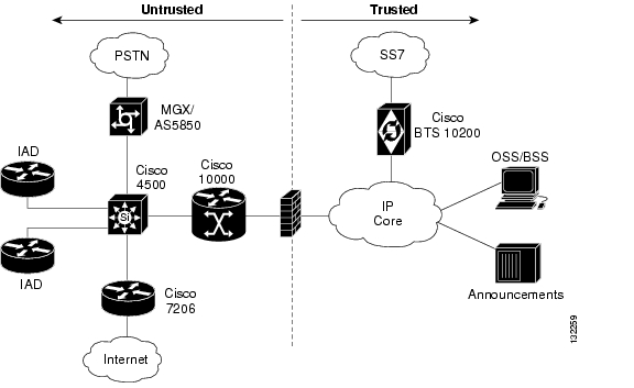
This chapter describes the significant threats to service that can occur from the untrusted portion of the Cisco BLISS for T1 network. It also describes the solutions to manage those security threats. The components in the untrusted portion of the network, for the purpose of solution security, are those included in the area to the left of the firewall as indicated in Figure 3-1. Basically, it includes all equipment deployed in the subscriber premises, the Internet Service Providers (ISPs) network, and the Internet. The trusted area can be assumed to be secure and not the source of an attack on the network.
In the Cisco BLISS for T1 network, the probable sources of attack are the Cisco 24xx, 2600, and 37xx in the customer premises equipment (CPE). Malicious traffic can also originate from the ISP's network or the Internet. It is reasonable to assume that all of the core elements, trunking gateways, Feature Servers, and the Call Agent are physically in a secure environment and not easily accessible to unknown or untrusted people.
Only Layer 3 and above security issues are addressed in this chapter. In the Cisco BLISS for T1 solution, it is assumed that each Integrated Access Device (IAD) has a secure and unshared physical connection into the core.
Figure 3-1 Cisco BLISS for T1 Security Zones
Security Design Goals
This section describes the plan for securing the Cisco BLISS for T1 network. Note that it is not possible to guarantee the complete security of an IP network. It is always possible to put more secure measures into the network at additional expense and complexity. The design described here attempts to balance the need for good security against network functionality/flexibility while minimizing the risk of an attack that could affect network operation.
This section includes the following sub-sections:
Trusted Zone
Most networks have a trusted zone where it is assumed an attack will not originate. The trusted zone is protected from the untrusted zone by a Cisco PIX Firewall. In the case of the Cisco BLISS for T1 network, the most important part of the network that must be protected is the Cisco BTS 10200 Call Agent and the Operations Support System (OSS) servers that provide key business functions. This part of the network requires the best possible protection because an intrusion incident can potentially disrupt service for all users.
PIX Filtering
Cisco PIX Firewalls will not restrict any traffic originating from the trusted zone. Hence, personnel working on OSS platforms can telnet to any part of the network. The Cisco PIX Firewalls are configured to allow only certain types of traffic from the untrusted zone of the network into the trusted zone.
The types of traffic allowed from the untrusted zone are listed below:
•
MGCP traffic—Signaling messages from voice gateways will be permitted through the Cisco PIX Firewalls. The Cisco PIX Firewall (Version 6.3) can be configured to allow MGCP messaging as an allowed application. In this setup, the Cisco PIX Firewall engine has predefined MGCP exchanges that it understands and permits. The MGCP application of the Cisco CallManager (the Enterprise voice solution) and the Cisco BTS 10200 Call Agent has been tested and proven to work well.
•
•
•
•
Note
The Cisco 10000 ESR would be configured to allow a ping to the serial interface. This would allow the IAD user to confirm connectivity with the Cisco 10000 ESR. Maintenance personnel can then confirm connectivity from the Cisco 10000 ESR to any point in the network. If it becomes necessary to confirm connectivity directly from the IAD to a point in the network, the ESR ACLs can be temporarily removed for testing.
•
The current plan would not permit Telnet sessions to originate from the untrusted portion of the network into the area behind the Cisco PIX Firewall. That means that maintenance personnel cannot telnet into a Cisco 10000 ESR, and from the Cisco 10000 ESR telnet to an OSS (or ssh to any point behind the firewall). This helps to protect the Cisco BTS 10200 and OSS if the untrusted portion of the network is breached. Maintenance personnel would be required to originate their Telnet sessions from behind the firewall to other points in the network.
PIX Interconnection Architecture
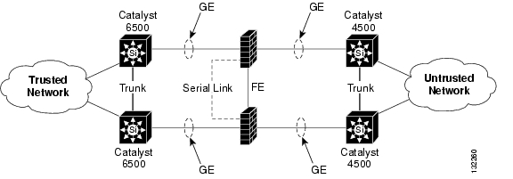
The Cisco PIX Firewalls are deployed as a redundant pair. The two Cisco PIX Firewalls communicate with each other over a serial link; a dedicated Ethernet connection for stateful operation. If the primary Cisco PIX Firewall fails, the secondary assumes forwarding traffic. The inside and outside LAN interfaces on each Cisco PIX Firewall are connected to an inside and outside VLAN respectively. Routing is handled by the Cisco 6500 switches on the inside and by the Cisco 4500 switches on the outside. Open Shortest Path First (OSPF) is used as the routing protocol to provide path determination as well redundancy.
Figure 3-2 PIX Interconnection Architecture
Untrusted Zone
The Cisco 10000 ESR, Cisco 7206, and Cisco MGX 88xx form the key part of the untrusted zone. The design is to place these three nodes on the same VLAN to allow for fast switching of packets between these devices and minimize jitter and latency. Note that all the internal interfaces on these devices are on private address space. Private address space is the primary mechanism used to protect the untrusted portion of the network from outsiders.
Cisco 7206 Risks
The entry point from the Internet would be via the Cisco 7206, which would require access control lists (ACLs) to perform the following functions:
•
•
•
IAD Risks
The IAD presents certain risks to the Cisco BLISS for T1 design. Because the IAD is a router located on the customer premise, the service provider does not physically control its network access. Although the vast majority of customers will treat IAD security carefully, it is possible that a customer can break into a router. To prevent a customer from accessing the router configuration through ROMMON, the no service password-recovery command can be used. It is also a recommended practice to configure ACLs on the IAD to perform the following functions:
•
•
Cisco MGX 88xx
This node does not have traffic originated by client computers and is not a potential source for an attack. We recommond installing an ACL to prevent incoming Telnet/SNMP access from any address except those in the OSS private address range. Using this ACL protects against unauthorized Telnet/SNMP traffic if a privately addressed device is compromised.
Announcement Servers
These nodes should reside behind the Cisco PIX Firewall to afford them the same level of security as other core devices because unavailability can affect large numbers of users. Based on performance numbers, the Cisco PIX 525 can support approximately 1800 Real-Time Protocol (RTP) streams. It is important when passing RTP traffic through the Cisco PIX firewall that you take into account the number of sessions that will have to be supported. The Cisco PIX 535 should be considered where higher capacity is a requirement.
NAT Consideration on IAD
In the Cisco BLISS for T1 network, Network Address Translation (NAT) can be used on the IAD for networks connected to an Ethernet port. Only traffic originating from the Ethernet interface is able to implement NAT. Voice traffic which originates from the IAD is not able to implement NAT. NAT configurations can vary depending on the requirements of the service provider's customer. Possible configurations are as follows:
•
•
•
In most cases, PAT is used to translate a range of private addresses that are assigned to the customer to a single public address. There will be cases where customers will require additional public IP addresses, have servers that they want to be publicly accessible, or have applications that do not work with NAT. In these cases NAT alone, NAT in conjunction with PAT, or no translation at all will have to be used to meet customer requirements.
Codec/Compression Alternatives
The G.726-32k, and G.711 codecs were tested as part of the Cisco BLISS for T1 Release 4.0 solution. The decision to use one codec over another is dependent on the amount of bandwidth available for the voice call(s) and the desired quality of the voice call(s). The measurement of quality is based on the Mean Opinion Score (MOS) which is a common benchmark used to determine the quality of sound produced by specific codecs. A higher score indicates a higher level of quality. G.711 has the highest MOS score and uses 64 kbps of bandwidth for a single voice call. G.726 has a lower MOS score than G.711 but only uses 32 kbps of bandwidth per call.
Although it might seem logical from a resource utilization standpoint to convert all calls to low-bit rate codecs to save on infrastructure costs, you should exercise additional care when designing voice networks with low-bit rate compression. One of the main drawbacks is signal distortion due to multiple encodings (called tandem encodings). For example, when a G.729 voice signal is tandem encoded three times, the MOS score drops from 3.92 (very good) to 2.68 (unacceptable). Another drawback is codec-induced delay with low bit-rate codecs.
DNS Redundancy Recommendations
We recommend that Domain Name Service (DNS) be used in a production Cisco BLISS for T1 deployment and that Server Load Balancing (SLB) be used to provide DNS server redundancy.
Specifying primary and secondary DNS server names in a device, such as the Cisco BTS 10200 or the IAD:
•
•
•
•
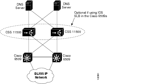
By using SLB functionality, either integrated in the Catalyst 6509 or external via CSS 11500 switches, a single DNS IP address (virtual IP address) can be specified in the Cisco BLISS for T1 device, such as the IAD or the Cisco BTS 10200. We recommend that the SLB function be configured using the round-robin load-balancing algorithm. In this way, DNS requests will be distributed evenly over the two DNS servers. If one of the servers fails, only 50 percent of the DNS requests made from the time the server fails until the SLB device detects the failure will be lost.
Figure 3-3 illustrates the use of SLB with external CSS 11500 devices. One could integrate the SLB function into the Catalyst 6509 core switches using IOS SL. The recommended product to provide DNS services is the Cisco Network Registrar (CNR). We also recommend that the DNS servers be dedicated for use by the Cisco BLISS for T1 VoIP network.
Figure 3-3 DNS Configuration with Server Load Balancers
CALEA
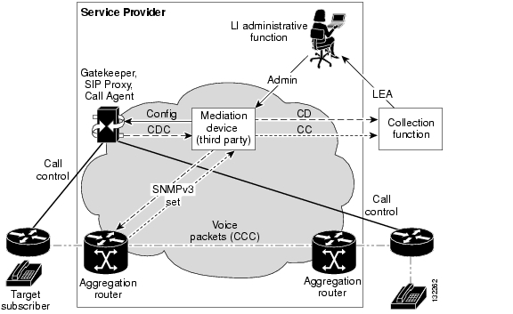
The Cisco BLISS for T1 solution provides interfaces for transmission of data used in conjunction with the Communications Assistance for Law Enforcement Act (CALEA). From a design perspective there are no hard guidelines on how the customer must implement the delivery function (DF) server/mediation device other than it must interface with the Cisco BLISS for T1 solution using the Service Independent Interface (SII) specification, as illustrated in Figure 3-4.
Customers have the option to acquire their own DF servers from companies like SS8 or Verint Systems or outsource the DF to a vendor like Fiducianet or Verisign. The advantage of the latter scenario is that the customer does not have to purchase, manage, or maintain the DF server. The typical arrangement is a monthly fee paid to the CALEA service provider with a charge assessed per trace incident. Some other important considerations are as follows:
•
•
•
Figure 3-4 CALEA Delivery Function
Internet Traffic Engineering Recommendations
The following recommendations are made regarding the Internet connection:
•
•
Figure 3-5 Internet Connections
Useful Scripts Recommendations
To support operations, we recommend that the Cisco BLISS for T1 customer develop scripts to perform the following functions:
•
•
•
•
•
•
Ancillary Server Recommendations
We recommend that the customer deploy two additional servers in the network: an NFS Server and a login server. These servers provide the functionality deescribed in the following sub-sections.
NFS Server
The NFS server can be any UNIX machine like a Sun Ultra with 40 GB disk space and RAM size like the Cisco BTS 10200 EMS platform. The NFS server has two purposes; namely the flash archiving recommended monthly and Oracle data backup. Ensure that the directory can be shared so the system can have access to it. The NFS server must be on the same subnet as the target Cisco BTS 10200 it serves.
Login Server
The login server acts as a secure gateway for any external user that might want to work on Cisco BTS 10200 or any other products in the Cisco BLISS for T1 network. This helps reduce security risk and also helps vendors, like Cisco, to post any images on this server so that the customer can download the image from here to the corresponding products. Also, if a network down situation occurs, Cisco engineers might need multiple logs and traces from the Cisco BTS 10200 and can just pull them directly from this server rather than stressing the production Cisco BTS 10200. For logs, if you can create separate subdirectories based on days in a month and months in a year, it is easy to go back to that particular directory to view the logs. The memory requirement is 1 GB and disk space of 5 to 10 GB is advisable.
Equipment Power, Space, and Mounting Requirements
The engineer designing the system should use the product datasheets to determine the power, space and mounting requirements for the individual products. Product datasheets can be found on the Cisco website at www.cisco.com.
![]()
![]()
![]()
![]()
![]()
![]()
![]()
![]()
Posted: Fri May 6 08:26:46 PDT 2005
All contents are Copyright © 1992--2005 Cisco Systems, Inc. All rights reserved.
Important Notices and Privacy Statement.