|
|

Table Of Contents
Cisco BLISS Solution Architecture
Cisco BLISS for T1 Solution Components
Reliability and Availability of Components
Cisco 10000 Edge Services Router
Cisco 7200 ISP Connection Gateway
Cisco AS5850 Universal Gateway
Solution Overview
Note
The product name of this solution is the "Cisco Broadband Local Integrated Services Solution (BLISS) for T1/E1." In the interest of brevity, in this document it is referred to as the "Cisco BLISS for T1 solution." All references to T1 apply equally to E1 configurations except where otherwise stated.
The Cisco Broadband Local Integrated Services Solution (BLISS) framework enables service providers primarily focused on serving their subscriber base via traditional high-speed access to deliver complete integrated services. The Cisco BLISS for T1 solution delivers packet voice and data services over a traditional T1 infrastructure. Using existing access lines, the Cisco BLISS for T1 solution allows service providers to offer a bundle of packet-based services including local and long-distance voice services and high-speed data. By providing multiple services over a common infrastructure, carriers can increase their revenue and profits, while simultaneously offering small and medium-sized business customers a better telecommunications value.
The Cisco BLISS for T1 solution uses MGCP-based centralized call-control architecture and uses an IP core for packet transport to team the Cisco BTS 10200 Softswitch with Cisco gateways to create a virtual switch network. The Cisco BTS 10200 has SIP and H.323 signaling interfaces for interconnection with SIP and H.323 voice networks. In addition, support for SIP endpoints is provided on the Cisco 7960, 7940, 7912, and 7905 IP phones.
This chapter includes the following sections:
•
•
Cisco BLISS Solution Architecture
There are currently three architectures for the Cisco BLISS solutions: Cable, Metro Ethernet, and T1. All three architectures are similar in terms of the backend components such as the Cisco BTS 10200, media gateways, and the core routing and switching components. Where they differ is in the access delivery method.
•
•
•
This document focuses on the Cisco BISS for T1 solution. The Cisco BLISS for Cable and Cisco BLISS for Metro Ethernet solutions are beyond the scope of this document and are covered in documentation dedicated to those technologies.
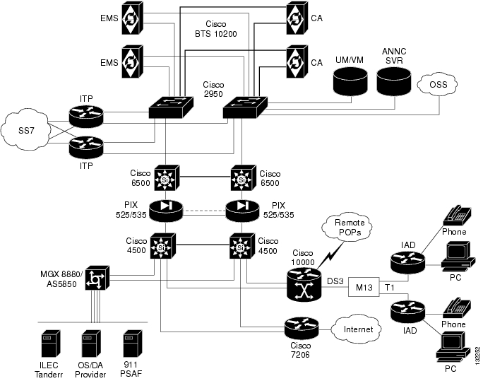
Figure 1-1 illustrates the Cisco BLISS for T1 solution architecture.
Figure 1-1 Cisco BLISS for T1 Solution Architecture
Cisco BLISS for T1 Solution Components
This section describes the following components of the Cisco BLISS for T1 solution:
•
•
•
•
•
Cisco BTS 10200 Softswitch
The Cisco BLISS for T1 solution uses the Cisco BTS 10200 Softswitch as a Call Agent (CA). Call Agent hosts used in this version of the solution are Sun-based platforms consisting of the Sun 240, Sun 440, and Sun 1280 platforms. The Call Agent application is active on only one Call Agent host platform at a time, and switches to the standby Call Agent host platform under failure conditions. The result is that Call Agent host failure and switchover events are invisible for established calls. Calls in the process of being set up during the switchover event cannot be preserved and must be reattempted. The Call Agent includes a scalable, open host that provides SIGTRAN interfaces, alarms, and a reliable IP link between the Call Agent and media gateways. The following sections provide detailed Call Agent specifications for Sun-based systems.
Logical Components
The Cisco BTS 10200 Softswitch consists of five independent logical components in a distributed architecture:
•
•
There are two types of FSs in the Cisco BTS 10200 Softswitch:
–
–
•
•
•
This section describes the functions provided by each of the logical components of the Cisco BTS 10200 Softswitch. The information is organized as follows:
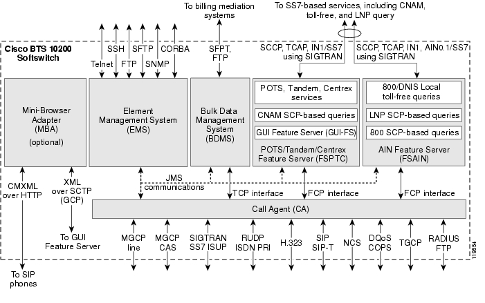
The architecture and interworking of the logical components (CA, FS, EMS, BDMS, and MBA) are shown in Figure 1-2.
Figure 1-2 Cisco BTS 10200 Softswitch Architecture, Showing Logical Components
CA Functions
The Call Agent (CA) provides monitoring and control of external network elements (NEs). It connects to multiple networks through the signaling adapter interface (see Figure 1-2). This interface converts incoming and outgoing signaling to and from the standard internal messaging format of the CA. This interface allows the CA to connect to multiple networks and exchange signaling messages for setup, teardown, and transfer of calls.
Signaling Adapter Interface
The signaling adapter interface performs the following functions:
•
•
•
•
Billing Data Generation and Interfaces
The CA supports the following billing data generation methods:
•
•
The following billing interfaces are provided for EMs on the CA (see Figure 1-3):
–
–
Note
Figure 1-3 CA Billing Interfaces
FS Functions
There are two different types of Feature Servers (FSs) in the Cisco BTS 10200 Softswitch.
•
•
Each FS communicates internally with the CA, and externally (via a signaling gateway) with signal transfer points (STPs) that are part of the SS7 signaling system. Note that although it is technically possible to place the Feature Servers and Call Agent on physically separate servers, we recommend they be installed on the same physical server.
The FSs provide access to features through a well-defined interface. The Cisco BTS 10200 Softswitch architecture logically separates the FSs (which provide feature control) from the CA (which provides call control) with a clear interface—Feature Control Protocol (FCP)—defined between them. The FSs provide support for POTS, Centrex, AIN, 8XX service, and other enhanced services. The FSs are colocated on the same machine as the CA.
An FS is invoked from a call detection point (DP) in the CA. For each DP, the CA checks if any triggers are armed. If a trigger is armed, the CA checks if the trigger applies to the subscriber, group, or office (in that order). If the trigger is applicable, the CA invokes the FS associated with that trigger. The Cisco BTS 10200 Softswitch call processing mechanisms are based on the ITU CS-2 call model.
The FSAIN supports the automatic call gap (ACG) function for communications with a service control point (SCP). When an SCP sends a message to the FSAIN regarding the allowed query rate, the Cisco BTS 10200 Softswitch adjusts its query rate accordingly.
EMS Functions
The Element Management System (EMS) manages all of the Cisco BTS 10200 Softswitch components and provides operations, administration, maintenance, and provisioning (OAM&P) interfaces for monitoring and control. It provides the following user OAM&P capabilities:
•
•
•
•
•
•
•
•
The internal database contains the provisioned data for basic call processing, billing, and special call features. Key data structures are stored in shared memory and are accessible to any process in the system. A library of read/write locks controls access to shared memory. The data structures are implemented using Oracle in the EMS/BDMS, and an indexed database (IDX) in the CA/FS.
The EMS provides a flexible mechanism to transport information over any protocol to any external device. The EMS interface design takes into account that each carrier has its own unique set of Operations Support Systems (OSSs). The EMS provides a decoupling layer between the external protocols used within the service provider network and the internal protocols of the Cisco BTS 10200 Softswitch. The core system does not need to interpret the specific data formats used by the other carrier network elements.
EMS Communications
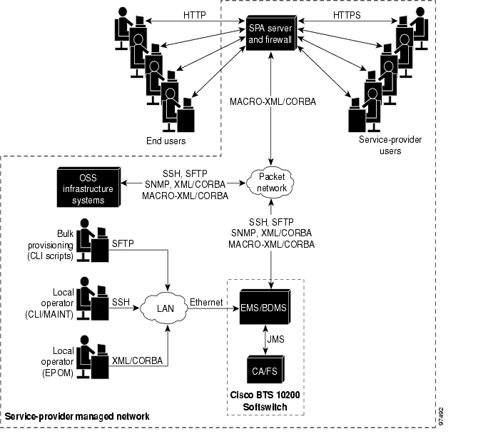
Operators, network administrators, and end users can communicate with the EMS from their workstations or PCs over the interfaces shown in Figure 1-4.
The user interfaces include the following:
•
–
–
•
•
–
–
–
•
The Cisco BTS 10200 Softswitch SNMP agent provides the following functions:
–
–
–
–
The SNMP agent supports SNMPv2c operations defined by the opticall.mib Management Information Base (MIB). The MIB is located in the directory /opt/BTSsnmp/etc on the EMS. The NMS needs to load the main MIB (opticall.mib) that will in turn import three other MIBs— IPCELL-TC, SNMPv2-TC, and SNMPv2-SMI. The main MIB uses variables from these MIBs.
•
Figure 1-4 Preferred EMS Management Interfaces for Service Provider and End Users
BDMS Functions
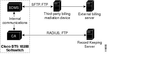
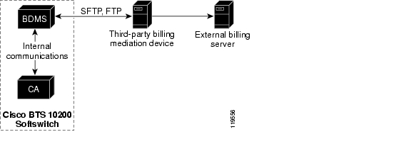
The Bulk Data Management System (BDMS) stores billing data in the form of call detail blocks (CDBs). CDBs are assembled from billing messages generated in the CA when billing-related call events occur during call processing. The BDMS formats the CDBs into a flat ASCII-file format, and transmits them to an external billing collection and mediation device that is part of the service provider billing system (see Figure 1-5). Finally, the BDMS forwards this data to an external billing mediation system or billing server, where it is assembled into CDRs.
The BDMS provides the following billing functions:
•
•
•
•
•
Figure 1-5 Billing Interface to the BDMS
MBA Functions
SIP phones interface via the IP network with the Mini-Browser Adapter (MBA) for services. The user accesses service functions via the "services" key on the SIP phone. A GUI on the SIP phone allows users to self-provision certain features. The MBA supports these services and performs GUI management for the GUI-enabled SIP-phone handsets.
The Cisco BTS 10200 Softswitch architecture illustrated in Figure 1-2 shows the MBA and its interfaces:
•
•
Reliability and Availability of Components
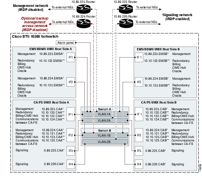
The Cisco BTS 10200 Softswitch network configuration is shown in Figure 1-6. This configuration provides redundant host machines for the EMS/BDMS and CA/FS components, redundant management local area networks (LANs), and six interfaces to the external routers. The configuration enhances security by separating management traffic from signaling traffic. As shown in the drawing, the service provider has the option of installing a backup management access network.
Figure 1-6 Cisco BTS 10200 Softswitch Network Configuration
Notes for Figure 1-6:
1.
–
–
–
–
2.
–
–
3.
–
–
–
–
4.
5.
Dual Active/Standby Configuration
Note
Each logical component (EMS, BDMS, CA, and FS) is deployed in a dual active/standby configuration, with the two sides running on separate computers (hosts). The active side of each component is backed up by a standby side on the other host. The communication paths among the components are also redundant. The redundant architecture supports the reliability and availability of the entire system. The active and standby sides of each logical component pair operate as follows:
•
•
•
•
•
•
Process Restartability
When a Cisco BTS 10200 Softswitch process exits due to an internal error (such as SIGSEGV on UNIX) or is terminated by the platform, the system automatically restarts the process that shut down. Restarting the process is a preferred alternative to switching over to the mate, because the restart preserves stable calls and also attempts to preserve transient calls. When a process is restarted, the process audits information such as resource states and attempts to repair inconsistencies. If a process experiences a high failure rate (even after repeated restarts), the system will switch over to the mate.
Additional information regarding the Cisco BTS 10200 Softswitch can be found at http://www.cisco.com/en/US/products/hw/vcallcon/ps531/index.html
Cisco ITP Signaling Gateway
Prior to the Cisco BTS 10200 Softswitch Release 4.x, the interface to the SS7 network was via a pair of SS7 termination cards inserted in the Cisco BTS 10200 chassis. Although serviceable, these SS7 cards had limitations that have now been addressed with the addition of the Cisco IP Transfer Point (ITP) as the Signaling Gateway for the Cisco BTS 10200. These limitations included scalability, flexibility, redundancy, serviceability, and support for open standards. The ITP addresses all of these issues with proven technology and a carrier class system.
The ITP was introduced to the Service Provider market in 2001 and is deployed globally with great success. As currently deployed, the ITP supports functionalities that include STP, Signaling Transport over IP and ATM, and Signaling Gateway for Next Generation end nodes like SSP and SCP. The ITP is certified by Telcordia as an ANSI STP, is completely open-standards based, and provides STP-class availability. The ITP is offered on multiple platforms and can scale from 4 links up to 800 links. e Table 1-1 highlights the ITP models and capacities.
Additional information regarding the Cisco ITP can be found at http://www.cisco.com/en/US/products/sw/wirelssw/ps1862/index.html.
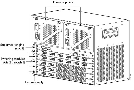
Cisco Catalyst 6509
The Catalyst 6509 is a multilayer switching component. It provides high port density Ethernet/Fast Ethernet, Gigabit switching functions, and Layer 3 routing. In the Cisco BLISS for T1 solution, it is used to provide Layer 2 connectivity to the Cisco BTS 10200 and to provide Layer 3 functionality for routing signaling packets to the edge and trunking gateways. Figure 1-7 shows the Catalyst 6509 core router.
Note that the Catalyst 6509 is purely a data switch and that there are no features specific to this platform required to support Cisco BLISS for T1. Therefore other platforms such as the Catalyst 4500 that support IRDP and L2/L3 functionality could be used. In addition other configurations of the Catalyst 6500 could be used, such as the Catalyst 6506 with the appropriate supervisor module and line cards to meet density and traffic requirements.
Cisco Catalyst 4506
The Catalyst 4506 is also multilayer switching component. It provides high port density Ethernet/Fast Ethernet, Gigabit switching functions, and Layer 3 routing. In the Cisco BLISS for T1 solution, it can be used to provide L2/L3 connectivity to the Cisco BTS 10200 as well as remote POPs that do not have a BTS. Figure 1-8 shows the Catalyst 4506 router.
Note that as with the Catalyst 6509, this switch is purely a data switch and that there are no features specific to this platform required to support the Cisco BLISS for T1 solution. Therefore, other platforms could be used in a mated pair to provide redundancy.
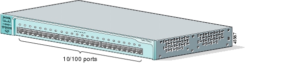
Cisco Catalyst 2950-24
The Catalyst 2950-24 ( Figure 1-9) is a Layer 2 switch that is deployed in a mated pair to provide redundant connectivity between the servers that comprise the Cisco BTS 10200. In addition, these switches provide the management and signaling interfaces to the Cisco BTS 10200. When the server hardware is purchased through Cisco, the 2950-24 switches are included. If the customer purchases the Cisco BTS 10200 server hardware through another vendor, they must purchase these switches separately.
Figure 1-7 Cisco Catalyst 6509
Figure 1-8 Cisco Catalyst 4506
Figure 1-9 Cisco Catalyst 2950-24 Router
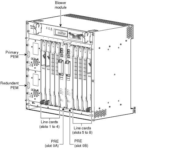
Cisco 10000 Edge Services Router
In the Cisco BLISS for T1 solution single or multiple T1 uplinks from customer premises equipment (CPE) are multiplexed into T3s and are aggregated at the Cisco 10000 Edge Services Router (ESR). The Cisco 10000 ESR is a Layer 3 platform that enables provisioning of IP QoS services, critical to maintaining voice quality, across thousands of leased-line and private line connections without performance degradation. The Cisco 10000 ESR accomplishes this by performing the application of QoS using Parallel Express Forwarding (PXF) hardware.
The Cisco IOS release used on the Cisco 10000 ESR is optimized for edge routing functions in the service providers networks. The software release includes a comprehensive set of standard features, including IP routing protocols, security services, and various commands to help configure and administer the router. In addition, this release supports advanced features, including quality of service (QoS), Multilink Point-to-Point Protocol (MLPPP), automatic protection switching (APS), and Communications Assistance for Law Enforcement Act (CALEA).
Cisco 10000 ESR Hardware
Figure 1-10 shows the layout of components in the Cisco 10000 ESR chassis.
Figure 1-10 Cisco 10000 ESR Chassis Layout
Deployment of the Cisco 10000 in the Cisco BLISS for T1 environment typically requires a combination of the following types of cards depending on the service provider environment.
Router Control
•
CPE Aggregation
•
•
•
IP Backhaul
•
•
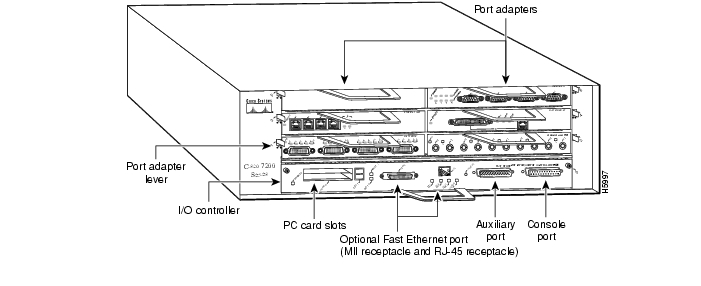
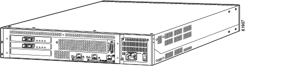
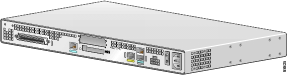
Cisco 7200 ISP Connection Gateway
The Cisco 7200 ISP Connection Gateway ( Figure 1-11) acts as the border router between the service provider network and the Internet. This router can deployed as a mated pair connected to two different Internet providers to provide redundancy or a single router if redundancy is not required or another POP's Internet connection will be used as a backup. Configuration of the router will vary depending on the interfaces required to connect to the Internet provider's network.
Figure 1-11 Cisco 7200 ISP Connection Gateway
Cisco PIX Firewall
Cisco PIX Firewalls ( Figure 1-12) provide advanced security services for multimedia and voice standards, including H.323 Version 4, SIP, Cisco Skinny Client Control Protocol, RTSP, and MGCP. The Cisco PIX Firewall protects the Cisco BTS 10200 from various IP attacks, such as denial of service (DOS), unauthorized access, and so on. The most appropriate Cisco PIX Firewall models for the Cisco BLISS for T1 solution are the 525 or 535 models. Selection of the firewall is based on throughput capacity as well as capacity of the VoIP signaling Application Layer Gateway (ALG). The ALG allows for the dynamic creation of holes in the firewall by examining IP port information in the signaling traffic.
Figure 1-12 Cisco PIX Firewall
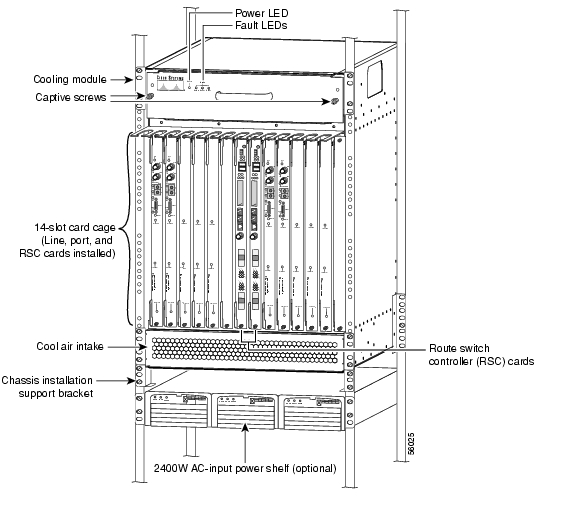
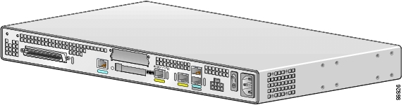
Cisco AS5850 Universal Gateway
The Cisco AS5850 Universal Gateway ( Figure 1-13) is a high-density universal gateway, with carrier-class attributes, offering highest capacity and high availability in its class. This gateway is designed to meet the demands of large, innovative service providers, supporting up to 5 Channelized T3s (CT3s), 96 T1s, 86 E1s, or 2 STM-1 (108 E1s) of data, voice, and fax services, on any port at any time. It offers high-availability features such as hot-swap on all cards, load-sharing and redundant hot-swappable power supplies, redundant fans and fan banks, redundant route switch controller (RSC) cards, and Call Admission Control (CAC), all part of the carrier-class attributes required to provide a highly available system.
The Cisco AS5850 can be used to terminate all trunks types associated with the Cisco BLISS for T1 solution. One consideration of deploying the Cisco AS5850 is the impact to voice calls in the event of an eRSC card failure. If the eRSC fails, then all transient and stable calls are lost. Upon failover to the standby eRSC, calls can be re-established. The advantage of the Cisco AS5850 gateway is that it runs Cisco IOS and provides the common IOS interface for configuration and troubleshooting.
Figure 1-13 Cisco AS5850 Universal Gateway
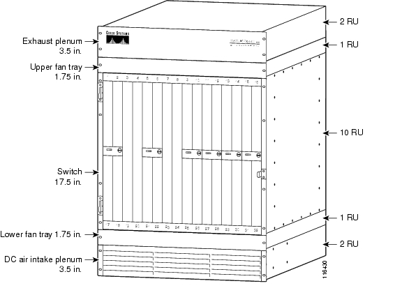
Cisco MGX 8880 Media Gateway
The Cisco MGX 8880 Media Gateway ( Figure 1-14) enables a range of packet voice applications for wireline, wireless and cable. With its comprehensive suite of quality of service (QoS) features and high-availability hardware and software, the Cisco MGX 8880 Media Gateway allows service providers to optimize their existing network infrastructure and lay the foundation for the delivery of advanced services and applications.
Figure 1-14 Cisco MGX 8880 Media Gateway
The advantage of using the Cisco MGX 8880 over the 8850 is improved pricing, three units fit into a 7-foot rack, and it provides a non-forklift upgrade to higher capacity using the VXSM.
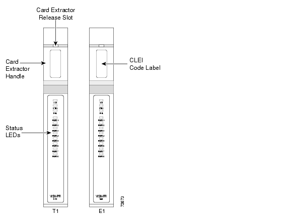
Cisco VISM-PR
The Cisco VISM-PR cards ( Figure 1-15) offer a field-proven full set of voice over IP (VoIP) and voice over ATM (VoATM) features, including toll-quality voice, fax, and modem. The Cisco VISM-PR cards can be deployed in standalone configurations or with softswitches to enable a variety of packet voice services in network architectures using the Media Gateway Control Protocol (MGCP), PacketCable Trunking Gateway Control Protocol (TGCP), H.323, and the Session Initiation Protocol (SIP).
Figure 1-15 Cisco VISM-PR Cards
Termination of the T1s to the VISM card can be done in a couple of ways. One is to use the 8-port T1 back card which provides the physical interfaces for the eight T1s supported on the card. There is a 1-to-1 relationship between back card and VISM. The second way is to use the SRM module with either the channelized OC-3 back card or the T3 back card. This card provides muxing functionality and provides connectivity to the VISMs via the Cisco MGX 8880 integrated TDM bus. In this scenario there is no back card used for the VISM.
All components in the VISM are capable of full redundancy. With the exception of the VISM, when a failure occurs, voice calls are not affected. When a failure occurs in the VISM, all voice calls active on that VISM are dropped and can be reestablished when the standby VISM becomes active. VISMs can be configured for 1:1 or 1:N redundancy.
Cisco MGX 8850 Series
The Cisco MGX 8850 is a high-density trunking gateway that is superseded by the Cisco MGX 8880, which was covered in the previous section. Applications which require a full-featured ATM switch will still require the Cisco MGX 8850, as the Cisco MGX 8880 only supports voice gateway functions. Note that both platforms are functionally equivalent in terms of voice capability using the VISM, but when using the VXSM (currently not part of the BLISS for T1 solution) the Cisco MGX 8880 provides greater feature depth. For more information on the VXSM, refer to http://www.cisco.com/univercd/cc/td/doc/product/wanbu/8850px45/vxsm/rel5/index.htm.
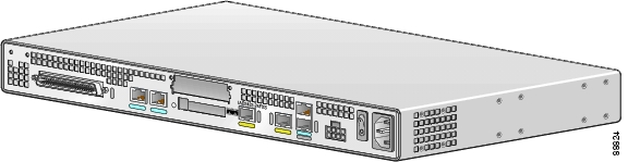
Cisco IAD2430 Series
Located at the customer site, the Cisco IAD2430 series provides support for analog phones (FXS and FXO ports). The uplink WAN connection is through T1 lines using PPP for Layer 2 link control. The Cisco IAD provides management MIBs and supports SNMP messages and northbound interfaces for network management. The Cisco IAD also provides remote access for element management and element configuration.
The Cisco IAD integrates user-side data, voice and fax signals and connects them to the wide area network (WAN) for transport by Voice over IP (VoIP).
Interfaces supported will depend on the model of the IAD and are as follows.
Voice
•
•
•
•
•
•
•
•
•
WAN
•
•
•
–
ADSL (WIC1-ADSL) or G.SHDSL (WIC1-SHDSL) for DSL uplink
WAN: WIC-1DSU-T1, VWIC-2MFT-T1, VWIC-2MFT-E1
–
–
The Cisco IAD can be placed on a desktop, or mounted on a wall or in a 19-inch rack.
Figure 1-16 through Figure 1-19 show the Cisco IADs supported in the Cisco BLISS for T1 solution.
Figure 1-16 Cisco IAD2431-8FXS Chassis
Figure 1-17 Cisco IAD2431-16FXS Chassis
Figure 1-18 Cisco IAD2431-1T1E1 Chassis
Figure 1-19 Cisco IAD2432-24FXS Chassis
Cisco SIP IP Phones
The Cisco SIP IP phones supported are the Cisco 7960, 7940, 7912, and 7905. The notable phone features are shown in Table 1-2.
IP Unity Announcement Server
The Harmony6000 Media Server is used as an announcement server in the Cisco BLISS for T1 solution; however, this server is built for high-speed, high-volume media processing. The carrier-grade hardware platform is specifically designed to overcome the challenges of delivering services such as interactive voice response (IVR), conferencing, announcements, automated speech recognition, text-to-speech and others, on a single platform (see http://www.ip-unity.com/solutions/harmony6000/)
This platform is provided by a third-party vendor and not directly through Cisco. Customers wishing to use this product should work directly with IP Unity to acquire the unit and obtain support. For additional information on IP Unity and its use in the Cisco BLISS for T1 solution, contact the Cisco Account Team.
Figure 1-20 IP Unity Harmony 6000 Announcement Server
![]()
![]()
![]()
![]()
![]()
![]()
![]()
![]()
Posted: Fri May 6 08:27:45 PDT 2005
All contents are Copyright © 1992--2005 Cisco Systems, Inc. All rights reserved.
Important Notices and Privacy Statement.