|
|

Table Of Contents
Overview of the VISM and VISM-PR Cards
Redundancy and Bulk Distribution
Redundancy with Bulk Distribution
Redundancy without Bulk Distribution
VoIP Switching and Switched AAL2 PVC Operating Modes
Overview of the VISM and VISM-PR Cards
This chapter provides a general introduction to VISM/VISM-PR cards and describes the hardware and software modules. The following topics are described:
•
"Card Service Types" section
•
•
The VISM/VISM-PR card, in combination with a Cisco MGX 8000 Series platform, enables telephone calls on conventional time-division multiplexed (TDM) voice circuits to be transported over an Asynchronous Transfer Mode (ATM) packet-switched and VoIP networks.
The VISM card is a single height card designed to operate in the following platforms:
•
•
•
The VISM-PR card is a single height card designed to operate in the following platforms:
•
•
•
•
•
•
Note
Card Types
VISM and VISM-PR cards are installed in Cisco MGX 8000 Series switches as front cards and their associated back cards—card sets.
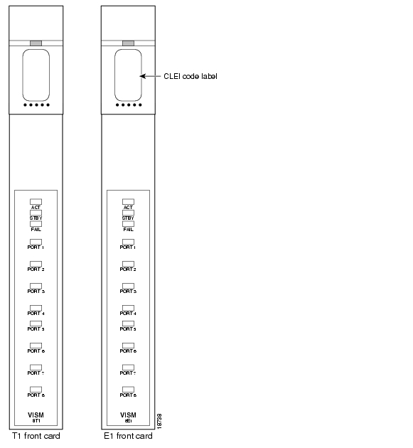
VISM has the following two types of front cards (see Figure 2-1):
•
•
Note
Figure 2-1 VISM T1 and E1 Front Cards
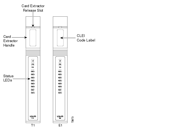
VISM-PR has the following two types of front cards (see Figure 2-2):
•
•
Figure 2-2 VISM-PR T1 and E1 Front Cards
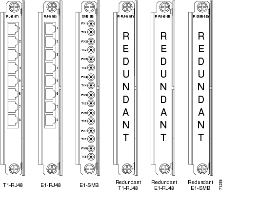
The VISM and VISM-PR front cards have the same associated back cards.
VISM/VISM-PR has the following two types of T1 back cards (see Figure 2-3):
•
•
VISM/VISM-PR has the following four types of E1 back cards (see Figure 2-3):
•
•
•
•
Figure 2-3 VISM T1 and E1 Back Cards
The VISM or VISM-PR card and MGX 8000 Series switch combination provides an interface, or voice gateway, between conventional TDM networks and packet-switched networks (see Figure 2-4).
Figure 2-4 Cisco MGX 8850 and VISM as a Voice Gateway
Connection to the packet network is performed by Cisco MGX 8000 Series switch Processor Module cards—PXM1, PXM1E, and PXM45—which communicate with a VISM/VISM-PR card through the switch midplane cellbus. See the documents listed in "Related Documentation" section on page xxx for more information on the MGX 8000 Series switch midplane cellbus.
Card Service Types
VISM/VISM-PR cards are configured with the following service types:
•
Note
•
•
VISM-PR card connections with the RPM-PR card requires the VBR (NRT) 3 service type on the PXM1E and PXM45 platforms.
If you are using a VISM-PR card in combination with a PXM1E, PXM45, or RPM-PR card, you must use the VBR (NRT) 3 selection when adding a connection.
The following connection service types can be configured with Release 3.2:
•
•
•
Card Physical Characteristics
VISM/VISM-PR cards are equipped with the following:
•
•
•
•
VISM/VISM-PR card architecture provides the following:
•
•
•
Figure 2-5 shows a simplified diagram of the VISM/VISM-PR architecture and major components.
Figure 2-5 VISM Card Block Diagram
The card is broadly divided into a TDM side and an ATM side. The T1/E1 framers, the array of DSPs, and the HDLC processor support the TDM side. The ATM adaptation layer (AAL) and the segmentation and reassembly (SAR) sections support the ATM side.
VISM is under the control of two independent processors. The main processor performs the control tasks—configuration, call setup and teardown, and management. The second processor, the data mover, handles the moving and processing of the voice and voiceband data traffic through the system.
The VISM card itself contains no ports for the connection of management stations. Workstations, PCs, or terminals used to manage VISM must be attached via the PXM card which provides both serial EIA/TIA-232 and Ethernet ports.
Card Features
VISM/VISM-PR cards process high-density digital voice circuits and provide dynamic compression, echo cancellation, dejittering, silence suppression, and packetization. The VISM/VISM-PR card uses the following features which you can configure:
•
–
–
–
•
Note
•
•
•
•
•
–
–
–
–
–
–
–
–
–
–
–
Note
•
•
•
•
•
•
•
•
•
•
•
•
•
•
•
•
Caution
Redundancy and Bulk Distribution
With or without bulk distribution, redundancy allows for the spare VISM card to automatically take over the functions of a failed VISM card.
After a VISM/VISM-PR card switches from standby to active, executing the dspcds command on the PXM shows the new active and standby cards. For example, the VISM card in slot 1.1 went from standby to active:
8850.1.8.PXM.a > dspcdsSlot CardState CardType CardAlarm Redundancy---- ----------- -------- --------- -----------1.1 Active VISM-8T1 Clear Covering slot 141.2 Reserved VISM-8T1 Clear1.3 Active VISM-8T1 Clear1.4 Empty Clear1.5 Active VISM-PR-8T1 Clear1.6 Empty Clear1.7 Standby PXM1-OC12 Clear1.8 Active PXM1-OC12 Minor1.9 Empty Clear1.10 Empty Clear1.11 Empty Clear1.12 Reserved VISM-8T1 Clear1.13 Active VISM-PR-8T1 Clear1.14 Standby VISM-8T1 Clear Covered by slot 11.15 Standby SRM-3T3 Clear1.16 Active SRM-3T3 Clear1.17 Empty Clear1.18 Active VISM-8T1 Major1.19 Empty ClearType <CR> to continue, Q<CR> to stop:However, when you change cards to the new active VISM/VISM-PR card using the cc command, the display shows the active card as standby.
8850.1.8.PXM.a > cc 1(session redirected)8850.1.1.VISM8.s >When the failed card is repaired, switching back to the repaired card is not automatic. You must manually change the repaired card back to the active state with the command line interface.
Note
Redundancy for VISM/VISM-PR cards with or without bulk distribution can be provided through the Service Redundancy Module (SRM) and SRM-E.
Redundancy for VISM/VISM-PR is also provided by Media Gateway Controller (MGC) redundancy groups. VISM/VISM-PR redundancy is cold redundancy in which ongoing calls do not persist during switchover in switching modes. In trunking modes, calls are persistent with minimal impact on traffic.
Note
See Table 2-1 for the support level for 1:N Service Module Redundancy (N = 1 through 11).
Note
Redundancy with Bulk Distribution
Redundancy with bulk distribution requires a spare VISM/VISM-PR card to be installed. The system uses the three T3 ports of the SRM back card instead of the normal T1 lines on the VISM/VISM-PR back cards.
Note
The TDM voice data transmitted or received over the T3 ports are distributed to the VISM/VISM-PR card as if they had been received over T1 back card ports in the normal manner. This feature reduces the number of physical lines required to support VISM, but requires external equipment to multiplex and demultiplex the T1 data onto the T3 lines.
Redundancy without Bulk Distribution
Redundancy without bulk distribution also requires a spare VISM/VISM-PR card equipped with a VISM/VISM-PR T1 redundant back card. In this arrangement the VISM/VISM-PR cards require and use their normal T1 back cards.
Redundancy can also be configured at the ATM permanent virtual circuits (PVCs) level. Two separate PVCs can be set up, each using a different PXM physical port and each routed to a separate router. Configure one PVC as active and the other as standby. Both PVCs are monitored by heartbeat OAM F5 loopback cells every 200 ms. If three consecutive OAM cells are lost, the PVC fails, and only the remaining PVC is active. A PVC recovers automatically when five consecutive OAM cells are received while the PVC remains in standby mode (no automatic fallback to active state is provided).
Control and bearer PVCs can be set up with a redundant PVC.
Operating Modes
The VISM/VISM-PR card performs in the following operating modes:
•
•
•
•
•
•
•
To support the operating modes, the VISM/VISM-PR card supports connections to the following three major interfaces:
1.
2.
3.
4.
In VoIP switching, switched AAL2 PVC, AAL1 SVC, and AAL2 SVC interfaces are always present and active. In AAL2 trunking mode, the interface to the call agent interface is not present, and the only active interfaces are to the TDM network and the ATM network.
The operating modes, combined with features you configure, can be used by VISM/VISM-PR cards in the following telephony applications:
•
•
•
VoIP Switching and Switched AAL2 PVC Operating Modes
In VoIP switching mode and switched AAL2 PVC mode, VISM/VISM-PR operates under the control of a call agent to set up and tear down calls. When a call is set up, VISM/VISM-PR transports voice payloads over an ATM network to the called station destination. /VISM-PR performs either as a voice gateway or as a multiservice access front end to a voice gateway.
Note
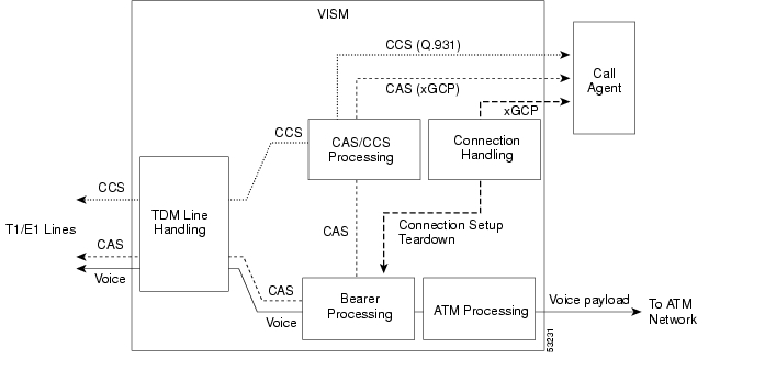
Figure 2-6 shows the major functional blocks and interfaces for the VoIP switching and switched AAL2 PVC operating modes.
Figure 2-6 VISM Block Diagram for VoIP Switching and Switched AAL2 PVC Operating Modes
The CAS signaling path on the TDM side is embedded in the voice stream but is separated at the bearer processing function. The CAS signaling then joins the CCS signaling path for CAS/CCS processing and is backhauled to the call agent. The path between the call agent and bearer processing, via a connection handling function, is for call setup and teardown.
Voice TDM Network Interface
The voice payload path is shown as a solid line along the bottom of Figure 2-6. All external TDM streams arrive and depart on the T1/E1 lines. Depending on the application, these streams consist of voice bearer channels (with or without CAS signaling) and separate CCS channels (if CCS signaling is used). The TDM line handling function provides the physical layer interface, which includes framing, line codes, clocking, loopbacks, physical alarms, and so forth. Bearer channels, including CAS, are sent to the bearer processing function. CCS channels are sent to the CAS/CCS processing function.
Further processing of the bearer channels is performed by the DSPs. This processing provides echo cancelling, compression, A/Mu law conversion, silence suppression, and fax/modem handling. If CAS signaling is present, signaling bits are extracted at the DSP stage and sent to the CAS/CCS processing function.
ATM Network Interface
The ATM processing function receives the processed DS0 voice streams and prepares them for transport over a packet network. The voice streams are divided into specific sample periods (for example, 5 ms or 10 ms) and formatted into service specific convergence sublayer (SSCS) packets appropriate for the method of transport over the ATM network. The available transport methods are VoIP (using AAL5) and voice over AAL2. Processing of the ATM packets further segments the voice payload into ATM cells for transport over the network using a SONET port on the PXM card.
Call Agent Interface
The call agent interface consists of CAS signaling or CCS signaling and call control. The path between the call agent and bearer processing, via a connection handling function, is for call setup and teardown.
The CAS signaling path on the TDM side is embedded in the voice stream (bearer DS0s) and is separated at the bearer processing function. The CAS signaling (robbed bits, digits, and tones) is passed to the CAS/CCS processing function where it is passed (backhauled) to the call agent under the control of the call agent. The mechanism for communicating between VISM/VISM-PR and the call agent is a gateway control protocol:
•
•
•
•
The separate CCS signaling path channels are passed to the CAS/CCS processing function and backhauled to the call agent. The CCS signaling is transported as ISDN Q.931 messages both on the TDM side and on the call agent side. On the TDM side, the messages are carried in the Q.921 layer protocol (which terminates at the VISM/VISM-PR card). On the call agent side, communication with the call agent consists of Q.931 messages encapsulated in RUDP/UDP/IP packets. The Q.931 connection is terminated at the call agent and not at the VISM/VISM-PR card.
The call control path uses MGCP, TGCP, SGCP, and SRCP for call setup and teardown. Because signaling and call control are so intertwined, both call control and CAS use the same path and protocol for the VISM/VISM-PR card-to-call agent communications.
AAL2 Trunking Operating Mode
In the AAL2 trunking operating mode, the VISM/VISM-PR card serves as an access to one or more trunks to preprovisioned locations. VISM/VISM-PR can be used at both ends of the trunk or at one end with a compatible device at the other.
In AAL2 trunking mode, VISM/VISM-PR plays no part in call setup and teardown. Other network elements handle call control while VISM/VISM-PR handles voice transport over the trunks. Figure 2-7 shows the major functional blocks for the AAL2 trunking operating mode.
Figure 2-7 VISM Block Diagram for the AAL2 Trunking Operating Mode
The AAL2 trunking mode is less complex than the VoIP switching and AAL2 PVC switched modes because call control is not involved, and a call agent is not needed.
The voice bearer path is treated in the same manner as in the VoIP switching and AAL2 PVC modes, except that only preprovisioned AAL2 PVCs are available for transport of voice over the trunks. The CAS signaling data is transported over the ATM network in the same AAL2 trunk as Type 3 messages. The CCS signaling data is transported over the ATM network in a separate AAL5 PVC.
VoIP Trunking Operating Mode
The Voice over IP (VoIP) trunking feature allows the VISM/VISM-PR to connect to the PBX, or central office digital systems, using T1/E1 digital interfaces. The TDM bit stream is converted into RTP packets, after echo cancellation and compression, and transports it over the IP network.
No call agent is required for setting up and tearing down calls. You must configure the DS0 circuits. The connection between VISM/VISM-PR and the first router is ATM. Then, the connection is IP only. VISM/VISM-PR and the router can have one or multiple PVCs to transport the data. You have the option to configure PVC for bearer or control. If the PVC is configured as bearer and no control PVC exists, then PRI signal traffic and bearer traffic go through this PVC. If you configure separate PVCs for control and bearer, PRI signaling goes through control traffic only. You can modify some of the connection parameters after the PVC is added.
CAS is transported to the far end using a Cisco proprietary format (not NSEs). PRI is transported over RUDP to the far end once the trunk is provisioned between the originating and terminating VISM/VISM-PR.
PRI transport is handled in a way identical to PRI backhaul except that the PRI traffic is sent to remote gateway instead of a call agent. You can configure one line for PRI trunking and another line for PRI backhauling.
You must provision the Link Access Procedure on the D-channel (LAPD) trunk when configuring one line for PRI trunking and another line for PRI backhauling.
You must configure a line number, remote gateway IP address, local UDP port, and remote gateway UDP port, and then open a trunk. You must then configure the D-channel as a trunk or backhaul:
•
Note
•
AAL1/AAL2 SVC Operating Mode
Release 3.2 supports the AAL1 and AAL2 switched virtual connection (SVC) operating modes for VISM-PR cards. AAL1 SVC is supported with the G.711 codec and clear channel.
Note
AAL2 SVC is supported with the G.711, G.726, G.729a, and G.729ab codecs and profiles 1, 2, 3, 7, 8, 100, 101, 110, and 200.
Note
![]()
![]()
![]()
![]()
![]()
![]()
![]()
![]()
Posted: Thu Jun 10 16:31:29 PDT 2004
All contents are Copyright © 1992--2004 Cisco Systems, Inc. All rights reserved.
Important Notices and Privacy Statement.