|
|

Table Of Contents
Installing VISM/VISM-PR Hardware and Software
VISM Cards in MGX 8000 Series Chassis
VISM-PR Cards in MGX 8000 Series Chassis
Installing VISM and VISM-PR Front and Back Cards
Removing VISM and VISM-PR Front and Back Cards
Applying Power to the VISM/VISM-PR Card
VISM/VISM-PR Upgrades with PXM1
VISM-PR Upgrades with PXM1E and PXM45
VISM/VISM-PR Downgrade Procedure
VISM to VISM-PR Hardware Upgrade
Installing VISM/VISM-PR Hardware and Software
This section describes how to install VISM/VISM-PR cards and how to upgrade the VISM/VISM-PR boot code and firmware. The following topics are described:
Hardware Installation
You can install VISM/VISM-PR cards in the following combinations:
•
Install a VISM/VISM-PR front card and a back card as a pair. The front and back cards must occupy the same slot.
•
Note
•
Note
In each of these configurations, connections to the packet network are made through the MGX 8000 Series cellbus and an OC-3 port located on the MGX 8000 Series PXM card. See the "Card Physical Characteristics" section on page 2-5 for more information on front and back cards.
VISM Cards in MGX 8000 Series Chassis
VISM front and back cards can be installed in the MGX 8000 Series platforms with the following basic guidelines:
•
•
•
The VISM card can be used with the PXM1 processor module.
VISM-PR Cards in MGX 8000 Series Chassis
VISM-PR front and back cards can be installed in the MGX 8000 Series platforms with the following basic guidelines:
•
•
•
The VISM-PR card can be used with the following processor modules:
•
•
•
You must install an additional fan tray spacer at the bottom of your MGX 8000 Series switch chassis directly above the intake plenum if you are using the VISM-PR card in combination with the PXM45 card.
Refer to the Cisco MGX 8850 (PXM45/PXM1E) Hardware Installation Guide for step-by-step instructions to install a fan tray.
MGX 8850 and MGX 8250 Chassis
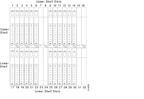
VISM and VISM-PR card installation in a Cisco MGX 8850 (PXM1 and PXM45) or a Cisco MGX 8250 platform consists of installing one front card and one back card (if not using the bulk distribution feature) in either the upper or lower shelf of the chassis.
You can use slots 1 to 6, 9 to 14, 17 to 22, and 25 to 30 to install VISM/VISM-PR cards (see Figure 3-1).
Figure 3-1 Available Chassis Slots for VISM Cards in the MGX 8850 and MGX 8250—Front View
Note
MGX 8230 and MGX 8830 Chassis
VISM/VISM card installation in a Cisco MGX 8230 platform and VISM-PR card installation in a Cisco MGX 8830 platform consist of installing one front card and one back card (if not using the bulk distribution feature) in either a left or right shelf slot.
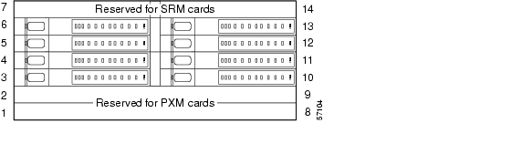
You can use slots 3 to 6, and 10 to 13 to install VISM/VISM-PR cards (see Figure 3-2 for an example of VISM cards in an MGX 8230). If you use all the available slots, you can configure the Cisco MGX 8230 or Cisco MGX 8830 with up to eight VISM cards.
Figure 3-2 Available Chassis Slots for VISM Cards in the Cisco MGX 8230—Front View
Installing VISM and VISM-PR Front and Back Cards
This section describes the following hardware installation procedures:
1.
2.
Installing a VISM or VISM-PR Front Card
Complete the following instructions to install a VISM or VISM-PR front card:
Step 1
Step 2
Caution
Installing a VISM or VISM-PR Back Card
Complete the following instructions to install a VISM or VISM-PR back card:
Step 1
When you insert the card into the slot, the levers should be vertical or horizontal along the line of the back card.
Step 2
Step 3
Step 4
Step 5
Note
Connecting Cables to Cards
After you install the VISM/VISM-PR front and back cards, connect the T1 or E1 cables to the RJ-48 or SMB connectors on the back cards. The T1 and E1 cables connect the eight ports on the back cards to the voice T1 or E1 lines. The T1 lines use RJ-48 connectors. The E1 lines use either RJ-48 or SMB connectors.
Note
Cabling for RJ-48 Connectors on T1 and E1 Ports
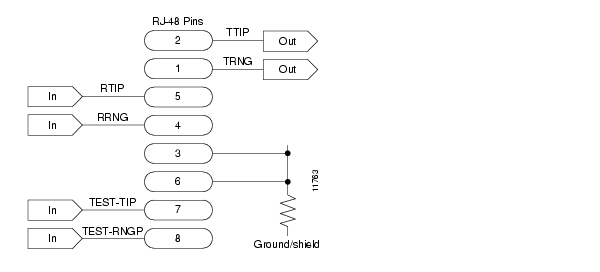
For T1 and E1 ports that connect through an RJ-48 connector, each connector has the following pins:
•
•
•
•
•
•
•
The connector wiring is shown in Figure 3-3.
Figure 3-3 RJ-48 PIN Connector
Cabling for SMB Connectors on E1 Ports
When you use the E1 VISM/VISM-PR back card with SMB cables, the E1 trunk cables connect the customer DSX-1 cross-connect point or E1 channel service unit (CSU) to the node using 75-ohm coaxial cable fitted with SMB connectors.
Removing VISM and VISM-PR Front and Back Cards
This section describes how to remove VISM/VISM-PR front and back cards and contains the following topics:
•
•
Removing a VISM or VISM-PR Front Card
To remove a VISM or VISM-PR front card, complete the following steps.
Step 1
Step 2
Step 3
Removing a VISM or VISM-PR Back Card
To remove a VISM or VISM-PR back card, complete the following steps:
Step 1
Step 2
Step 3
This action starts the removal of the card.
Step 4
Applying Power to the VISM/VISM-PR Card
Apply power to a VISM/VISM-PR card by installing the card in an already running MGX 8000 Series platform. Or, apply power to a chassis that has a previously installed VISM/VISM-PR card.
When power is applied, the VISM/VISM-PR card performs extensive testing and initialization functions. If the card has already been configured, the initialization downloads the configuration data from the disk on the PXM. This process takes approximately two minutes, during which the LED indicator blinks. When the Active LED becomes solid green, the card is in the Active state and is ready to be configured (if necessary) and is able to process data.
Software Upgrades
VISM/VISM-PR Release 3.2 provides a graceful upgrade procedure for the following releases:
•
•
•
•
•
Caution
Prerequisites
To ensure that the VISM/VISM-PR configuration is preserved throughout the upgrade procedure, you must complete the prerequisites listed in this section.
Before starting the graceful upgrade procedure, complete the following prerequisites:
•
For more information on adding redundancy, refer to the add redundancy, addred, command in the Cisco MGX 8250, Cisco MGX 8230, and Cisco MGX 8850 PXM1-based Command Reference documentation and the Cisco MGX 8830 and MGX 8850 PXM1E/ PXM45-based Command Reference documentation.
•
•
•
VISM/VISM-PR Upgrades with PXM1
This section describes the procedures for upgrading VISM/VISM-PR software when the VISM/VISM-PR is used with a PXM1 card.
Download VISM/VISM-PR Boot Code and Firmware to PXM1
To download the VISM/VISM-PR boot code and firmware to the PXM1 card, use TFTP.
Step 1
Step 2
Step 3
a.
b.
c.
d.
Step 4
To upgrade all VISM cards, proceed to Step 4 c. To upgrade an individual VISM card, proceed to Step 4 d.
a.
b.
c.
quit
d.
quit
Note
Upgrade VISM/VISM-PR Firmware with PXM1 Card
Software Release 3.2 is for VISM and VISM-PR cards. Ensure that the VISM and VISM-PR cards have the minimum boot code version of vism_8t1e1_VI8_BT_3.2.00.fw.
The following versions of VISM software Release 3.2 are available:
•
•
In this procedure the following conditions apply:
•
•
•
Perform the firmware upgrade on the VISM or VISM-PR cards. Do not remove the VISM cards and replace them with VISM-PR cards at this time.
Step 1
Step 2
savesmcnf <SM slot#>
This command saves the existing configuration in the C:CNF directory. This file can be used during the downgrade procedure, if necessary.
Step 3
install sm <SM slot#> <new-rev>
where:
SM slot# is the slot number of the primary VISM or VISM-PR card and new-rev is the file name of the new firmware (for example, vism_8t1e1_003.002.000.000.fw).
This command causes the secondary VISM or VISM-PR card to reset and come up in the standby state, running the new-rev firmware. The primary VISM or VISM-PR card is unaffected by this command.
Step 4
newrev sm <SM slot#> <new-rev>
where:
SM slot# is the slot number of the primary VISM or VISM-PR card and new-rev is the filename of the new firmware.
This command causes the primary VISM or VISM-PR card to reset and the secondary VISM or VISM-PR card to become active and running the new-rev firmware.
Step 5
commit sm <SM slot#> <new-rev>
where:
SM slot# is the slot number of the primary VISM or VISM-PR card and new-rev is the filename of the new firmware.
The two VISM or VISM-PR cards are now back to their original condition except that both cards are now running the new-rev firmware.
Step 6
Note
It is also recommended that you perform the following verifications:
•
•
•
Note
For more information about the VISM and VISM-PR card specifications, see "VISM and VISM-PR Release 3.2 Specifications".
Boot Code Upgrade Procedure with PXM1 Cards
Complete the following steps to upgrade the new backup boot code when you are using PXM1 cards in your MGX 8230, MGX 8250, and MGX 8850 chassis:
Note
Step 1
Note
Step 2
a.
b.
Caution
c.
Caution
When the boot code is being written to PROM, you will see comments displayed at the VISM prompt. This behavior is normal and expected.
Step 3
Step 4
Note
You have completed upgrading the new VISM backup boot code.
VISM-PR Upgrades with PXM1E and PXM45
This section describes the procedures for upgrading VISM-PR software when the VISM-PR is used with a PXM1E or PXM45 card.
Download VISM-PR Boot Code and Firmware to PXM1E and PXM45
To download the VISM-PR boot code and firmware to the PXM1E or PXM45 card, use FTP.
Step 1
Step 2
ftp node-ip
where node-ip is the IP address of the node to which you want to download the image.
Step 3
Step 4
Step 5
cd C:FW
Step 6
put image-version
where image-version is the downloaded image from Step 1.
Step 7
Upgrade VISM-PR Firmware with PXM1E and PXM45 Cards
Ensure that the VISM-PR cards have the minimum boot code version of vism_8t1e1_VI8_BT_3.2.00.fw.
The following versions of VISM-PR software Release 3.2 are available:
•
•
Perform the firmware upgrade on the VISM-PR cards.
Step 1
Step 2
Step 3
Step 4
loadrev sm-primary-slot-num new-rev
where sm-primary-slot-num is the slot number of the VISM-PR card in which you want to install the new software; and new-rev is the new firmware version number for the VISM-PR software.
Caution
Step 5
runrev sm-primary-slot-num new-rev
Caution
Step 6
commitrev sm-primary-slot-num new-rev
You have completed the steps. Proceed to the Boot Code Upgrade Procedure with PXM1E and PXM45 Cards.
Boot Code Upgrade Procedure with PXM1E and PXM45 Cards
Complete the following steps to upgrade the new backup boot code when you are using PXM1E or PXM45 cards in your MGX 8000 Series chassis:
Step 1
Step 2
Step 3
The VISM-PR card automatically resets and becomes active with the latest boot code image. You have completed the boot code upgrade procedure.
VISM/VISM-PR Downgrade Procedure
Use this procedure to downgrade VISM software from software Release 3.2 to an earlier VISM release. By following the downgrade procedure described here, the configurations are retained after the downgrade.
Note
Complete the following steps to downgrade the VISM software from software Release 3.2 for VISM/VISM-PR to Release 3.1.2, 2.2, 2.1, or 1.5:
Step 1
delred <SM slot#>
Step 2
Step 3
clrsmcnf <SM slot#>
where:
SM slot# is the slot number of the VISM card to be downgraded.
The VISM card resets on executing this command. Wait for the card to come active.
Step 4
restoresmcnf -f <filename> -s <SM slot#>
where:
The filename is the name of the old configuration file that was saved while the old-rev firmware was running. The file can be found in the C:CNF directory on the MGX shelf.
The SM slot# is the slot number of the VISM card to be downgraded.
The VISM card resets again. When the card becomes active, it has the old-rev firmware running with the old configuration.
Step 5
VISM to VISM-PR Hardware Upgrade
Complete the following steps to upgrade your system from VISM cards to VISM-PR cards.
Caution
Step 1
Step 2
Step 3
Step 4
Step 5
Step 6
Step 7
Step 8
Step 9
Step 10
Step 11
Step 12
![]()
![]()
![]()
![]()
![]()
![]()
![]()
![]()
Posted: Thu Jun 10 16:30:54 PDT 2004
All contents are Copyright © 1992--2004 Cisco Systems, Inc. All rights reserved.
Important Notices and Privacy Statement.