|
|

Line and port management screens facilitate viewing, configuring, and deleting the following voice and data services:
The line status screen is the entry point for many configuration and monitoring tasks. Each line displays a row of icons that are hyperlinks to other configuration tasks (see Figure 4-1).

The line configuration screens use the following icons to launch line configuration tasks:
The first six icons in Table 4-1 are displayed in the Select column for each line. Click on the desired icon to perform the specified line configuration task.
Along the top of the table is another row of icons, some of which are active buttons. Use the + and - icons in this group to add or delete lines. The rest of these icons are legends only.
This chapter describes how to view, add, configure, and delete Cisco MGX 8260 lines and ports. For alarm and performance procedures, see "Alarms and Performance."
See the following sections for line configuration tasks.
This section describes the procedures for viewing DS0 Channels. This part of the Cisco WebViewer is provided as a convenience; DS0s are actually voice channels that are described in a later section.
To view DS0 channel status, follow these steps:
Step 1 On the Navigation pane, click Line.
Step 2 Click Dsx0.
Step 3 Click All-Dsx0.
The Dsx0 Status screen opens.
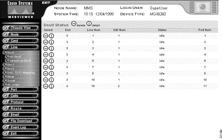
Step 4 Interpret the table as follows:
| Table Entry | Description |
|---|---|
Slot | The logical slot number |
Line | The corresponding DS1/E1 line number |
DS0 Number | The DS0 number within the DS1/E1 |
Status | The DS0 channel status:
|
Port number | The port number associated with this DS0 |
To view selected lines, follow these steps:
Step 1 On the Navigation pane, click Line.
Step 2 Click Dsx0.
Step 3 Click Selective-Dsx0.
The selection form opens.

Step 4 Enter the DS0 selection criteria:
| Criteria | Description |
|---|---|
Slot Number | The desired slot number. Valid settings are 1-16 and All. |
Line Number | The DS0 channel number. Values: 1 to 24 for DS1, 1 to 30 for E1, and All. |
Port Status | The port status:
|
Step 5 Click Display.
The Dsx0 Status screen opens, displaying the lines that meet the selection criteria.
You add DS0 channels indirectly by adding voice ports that use DS0s. For more information, see Adding Voice Ports.
You change DS0 channels indirectly by changing voice ports that use DS0s. For more information, see Changing Voice Ports.
To delete a DS0 channel, follow these steps:
Step 1 On the Navigation pane, click Line.
Step 2 Click Dsx0.
Step 3 Click All-Dsx0.
The Dsx0 Status screen opens.
Step 4 On the Dsx0 Status screen, click the - icon for the line you want to delete.
Step 5 Confirm your action.
The system deletes the DS0 channel.
This section describes the procedures for adding and changing DS1 Lines. The DS1 and E1 modes are mutually exclusive; these procedure assume the chassis is set to the DS1 mode.
To view DS1 line status, follow these steps:
Step 1 On the Navigation pane, click Line.
Step 2 Click Dsx1-T1.
Step 3 Click All-Lines.
The Dsx1-T1 Line Configuration screen opens.

Step 4 Interpret the columns as follows:
| Column Entry | Description |
|---|---|
Slot | The logical slot number. |
Line | The DS1 line number. |
Ds3 Line | The related DS3 line number. |
Line Type | The type of DS1 line implemented in this circuit:
|
Line Coding | The coding used for zero code suppression on this line:
|
Line Status | The DS1 line status, displayed as a row of indications. For more information, see Viewing Alarms for All DS1/E1 Lines. |
Status | The administrative status of the line. The values are up or down when using the IPDC call control protocol. Otherwise, the status indicator is always up. |
To view selected lines
Step 1 On the Navigation pane, click Line.
Step 2 Click Dsx1-T1.
Step 3 Click Selective-Lines.
The selection form opens.

Step 4 Enter the DS1 selection criteria:
| Criteria | Description |
|---|---|
Slot Number | The desired slot number. Valid settings are 1-16 and All. |
Line Coding | The line coding:
|
Related Dsx3 Line | The corresponding Dsx3 Line:
|
Line Type | The line type:
|
Line Status | The line status:
|
Step 5 Click Display.
Step 6 The Dsx1-T1 Line Configuration screen opens, displaying the lines that meet the selection criteria.
To add DS1 Lines, follow these steps:
Step 1 On the Navigation pane, click Line.
Step 2 Click Dsx1-T1.
Step 3 Click All-Lines.
The Dsx1-T1 Line Configuration screen opens.
Step 4 On the Dsx1-T1 Line Configuration screen, click the + icon.
The Add Dsx1-T1 Line form opens.
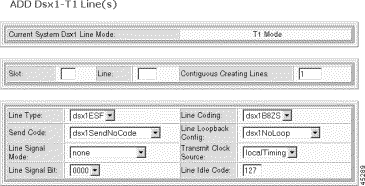
Step 5 Specify the line configuration:
| Parameter | Description |
|---|---|
Slot | The logical number of the slot in the MGX 8260 chassis. Valid entries: NSC: 1-8 BSC: 11-16 |
Line | The number of the DS1 line. Valid entries: Valid line numbers: NSC: 1-16 BSC: 1-168 as shown by the following table of DS1 to DS3 mappings. DS3 Line Number DS1 Line Number 501 1-28 502 29-56 503 57-84 504 85-112 505 113-140 506 141-168 |
Contiguous Creating Lines | The number of contiguous DS1 Lines to add. The stops adding lines at the first failure. |
Line Type | The type of framing, as follows:
|
Send Code | The type of code sent across the DS1 interface by the Cisco MGX 8260. The valid settings are:
|
Line Signal Mode | The signal mode for the transmit direction. In the receive direction, it is always set to robbed bit. The valid settings are:
|
Line Signal Bit | The 4-bit signaling pattern to send. Values: 0000 to 1111 binary |
Line Coding | The line coding format. The valid settings are:
|
Line Loopback Config | The loopback configuration of the DS1 interface. The valid settings are:
|
Transmit Clock Source | The clock source for the transmit signal:
|
Line Idle Code | The code that indicates the idle condition. Values 0-127 |
Step 6 Click Add. The system adds the DS1 lines.
 |
Note When adding contiguous lines, the system stops adding lines if an error occurs. |
To change the configuration of a DS1 line, follow these steps:
Step 1 On the Navigation pane, click Line.
Step 2 Click Dsx1-T1.
Step 3 Click All-Lines.
The Dsx1-T1 Line Configuration screen opens.
Step 4 On the Dsx1-T1 Line Configuration screen, click the i icon on the row of the line you want to change.
The Dsx1-T1 Line Status and Configuration screen, which contains the configuration form, opens.

Step 5 Scroll to the bottom of the form to see the Dsx1-T1 Line Configuration pane.
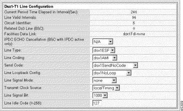
The Dsx1-T1 Line Configuration pane displays the following read-only information:
| Information | Description |
|---|---|
Current Period Time Elapsed | The number of seconds since the start of the near end error measurement period. |
Line Valid Intervals | The number of 15 minute intervals during which the system collected valid data for the near end. |
Circuit Identifier | A text string describing the line. |
Related Ds3 Line | The corresponding Ds3 line. |
Facilities Data Link | The type of facility data link: dsx1Fdl-none. |
Step 6 Configure the DS1 line by changing the desired parameters. For a description of the DS1 parameters, see Adding DS1 Lines.
Step 7 Click Modify. The system applies the configuration changes.
To delete a single DS1 line, follow these steps:
Step 1 On the Navigation pane, click Line.
Step 2 Click Dsx1-T1.
Step 3 Click All-Lines.
The Dsx1-T1 Line Configuration screen opens.
Step 4 On the Dsx1-T1 Line Configuration screen, click the - icon for the line you want to delete.
Step 5 Confirm your action.
The system deletes the DS1 line.
To delete a range of DS1 lines, follow these steps:
Step 1 On the Navigation pane, click Line.
Step 2 Click Dsx1-T1.
Step 3 Click All-Lines.
The Dsx1-T1 Line Configuration screen opens.
Step 4 On the Dsx1-T1 Line Configuration screen, click the - icon in the top row of icons.
The Delete Dsx1 Lines form opens.
Step 5 Specify the number of lines:
| Setting | Description |
|---|---|
Contiguous Deleting Lines | The number of lines to delete |
Step 6 Click Delete and confirm your action.
The system deletes the DS1 lines.
This section describes the procedures for adding and changing E1 lines. The DS1 and E1 modes are mutually exclusive; these procedure assume the chassis is set to the E1 mode.
To view E1 line status, follow these steps:
Step 1 On the Navigation pane, click Line.
Step 2 Click E1.
Step 3 Click All-Lines.
The E1 Line Configuration screen opens.
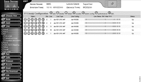
Step 4 Interpret the columns as follows:
| Column Entry | Description |
|---|---|
Slot | The logical slot number. |
Line | The E1 line number. |
Line Type | The type of framing:
|
Line Coding | The line coding format:
|
Line Status | The E1 line status, displayed as a row of twelve indications.For more information, see Viewing Alarms for All DS1/E1 Lines. |
Status | The administrative status of the line. The values are up or down when using the IPDC call control protocol. Otherwise, the status indicator is always up. |
To view selected lines, follow these steps:
Step 1 On the Navigation pane, click Line.
Step 2 Click E1.
Step 3 Click Selective-Lines.
The selection form opens.

Step 4 Enter the E1 selection criteria:
| Criteria | Description |
|---|---|
Slot Number | The desired slot number. Valid settings are 1-16 and all. |
Line Coding | The line coding:
|
Line Type | The line type:
|
Line Status | The line status:
|
Step 5 Click Display.
Step 6 The E1 Line Configuration screen opens, displaying the lines that meet the selection criteria.
To add E1 lines, follow these steps:
Step 1 On the Navigation pane, click Line.
Step 2 Click E1.
Step 3 Click All-Lines.
The E1 Line Configuration screen opens.
Step 4 On the E1 Line Configuration screen, click the + icon.
The Add DSX1 Line form opens.
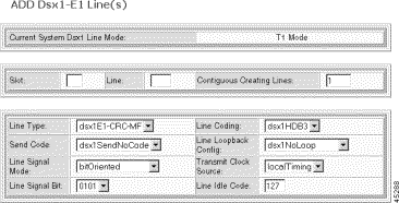
Step 5 Specify the line configuration:
| Parameter | Description |
|---|---|
Slot | The logical number of the slot in the MGX 8260 chassis. Valid entries: NSC: 1-8, 11-16 |
Line | The number of the E1 line or the first line in a range of lines. Valid entries: NSC: 1-16 |
Contiguous Creating Lines | The number of contiguous E1 lines to add with this configuration. The MGX 8260 stops adding lines at the first failure. |
Line Type | The framing format:
|
Send Code | The type of code sent across the E1 interface by the Cisco MGX 8260. The only valid settings are:
|
Line Signal Mode | The signal mode for the transmit direction. In the receive direction, it is always set to robbed bit. The valid settings are:
|
Line Signal Bit | The signaling bit pattern to transmit. Values: 0000 to 1111 (binary). Default: 0101 |
Line Coding | The line coding format:
|
Line Loopback Config | The loopback configuration of this interface.
|
Transmit Clock Source | The clock source for the transmit signal.
|
Line Idle Code | The idle code to transmit on each idle DS0 channel. Values: 0 to 255. Default: 127 |
Step 6 Click Add. The system adds the E1 lines.
 |
Note When adding contiguous lines, the system stops adding lines if an error occurs. |
To change the configuration of a E1 line, follow these steps:
Step 1 On the Navigation pane, click Line.
Step 2 Click E1.
Step 3 Click All-Lines.
The E1 Line Configuration screen opens.
Step 4 On the E1 Line Configuration screen, click the i icon on the row of the line you want to change.
The E1 Line Status and Configuration screen, which contains the configuration form, opens:
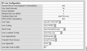
The configuration pane at the bottom of the form displays the following read-only information:
| Information | Description |
|---|---|
Current Period Time Elapsed | The number of seconds since the start of the near end error measurement period. |
Line Valid Intervals | The number of 15 minute intervals during which the system collected valid data for the near end. |
Circuit Identifier | A text string describing the line. |
Related DS3 Line | The DS3 line that contains this E1 line. Zero means not applicable. |
IPDC ECHO Cancellation | The echo cancellation state, when applicable. |
Facilities Data Link | The type of facility data link: dsx1Fdl-none. |
Step 5 Configure the E1 line by changing the desired parameters. For a description of the E1 parameters, see Adding E1 Lines:
Step 6 Click Modify. The system applies the configuration changes.
To delete a single E1 line, follow these steps:
Step 1 On the Navigation pane, click Line.
Step 2 Click E1.
Step 3 Click All-Lines.
The E1 Line Configuration screen opens.
Step 4 On the E1 Line Configuration screen, click the - icon for the line you want to delete.
Step 5 Confirm your action.
The system deletes the E1 line.
To delete a range of E1 lines, follow these steps:
Step 1 On the Navigation pane, click Line.
Step 2 Click E1.
Step 3 Click All-Lines.
The E1 Line Configuration screen opens.
Step 4 On the E1 Line Configuration screen, click the - icon in the top row of icons.
The Delete E1 Lines form opens.
Step 5 Specify the number of lines:
| Setting | Description |
|---|---|
Contiguous Deleting Lines | The number of lines to delete |
Step 6 Click Delete and confirm your action.
The system deletes the E1 lines.
This section describes the procedures for adding and changing DS3 lines.
To view DS3 line status, follow these steps:
Step 1 On the Navigation pane, click Line.
Step 2 Click Dsx3.
Step 3 Click All-Lines.
The Dsx3 Line Configuration screen opens.

Step 4 Interpret the table as follows:
| Table Entry | Description |
|---|---|
Slot | The slot number of the card with the DS3 line |
Line | The line number of the card with the DS3 line |
Line Type | The DS3 C-bit usage:
|
Line Coding | The zero code suppression for this interface: dsx3B3ZS |
Line Status | The DS3 line status displayed as a row on indicators. Interpret the bits from right to left as follows:
|
Loopback Config | The source for the transmit signal clock:
|
To view selected lines, follow these steps:
Step 1 On the Navigation pane, click Line.
Step 2 Click Dsx3.
Step 3 Click Selective-Lines.
The selection form opens.

Step 4 Enter the DS3 selection criteria:
| Criteria | Description |
|---|---|
Slot Number | The desired slot number. Valid settings are 1-16 and all. |
Loopback Config | The loopback configuration of the line:
|
Line Type | The line type:
|
Line Status | The line status:
|
Step 5 Click Display.
The Dsx3 Line Configuration screen opens, displaying the lines that meet the selection criteria.
To add DS3 lines, follow these steps:
Step 1 On the Navigation pane, click Line.
Step 2 Click Dsx3.
Step 3 Click All-Lines.
The Dsx3 Line Configuration screen opens.
Step 4 On the Dsx3 Line Configuration screen, click the + icon.
The Add Dsx3 Line form opens.
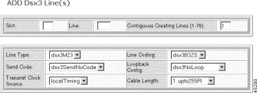
Step 5 Specify the line configuration:
| Parameter | Description |
|---|---|
Slot | The logical number of the slot in the MGX 8260 chassis. Valid entries: BSC: 11-16 DMC: 7-8 |
Line | The number of the DS3 line, or the starting number of a range of DS3 lines. Valid line numbers: BSC: 501-506 DMC: 1-6 (reserved for future use) |
Contiguous Creating Lines | The number of contiguous DS3 lines to add with this configuration. |
LineType | Indicates the DS3 C-bit usage or E3 application:
|
Line Coding | The data coding scheme this line. Fixed at dsxB3ZS. |
Send Code | No code is sent across the DS3 interface by the Cisco MGX 8260. The only valid setting is:
|
Loopback Config | Specifies the loopback test state:
|
Transmit Clock Source | The clock source for the transmit signal:
|
Cable Length | The approximate length of the line: upto255Ft—1-255 ft. bt255To300—225-300 ft. bt300To450—300-450 ft. bt450To900—450-900 ft. |
Step 6 Click Add.
The system adds the DS3 lines.
 |
Note When adding contiguous lines, the system stops adding lines if an error occurs. |
To change the configuration of a DS3 line, follow these steps:
Step 1 On the Navigation pane, click Line.
Step 2 Click Dsx3.
Step 3 Click All-Lines.
The Dsx3 Line Configuration screen opens.
On the Dsx3 Line Configuration screen, click the i icon on the row with the line you want to modify.
Step 4 The Dsx3 Line Status and Configuration form opens, which contains the following configuration screen:

Step 5 Configure the DS3 line. For parameter definitions, see Adding DS3 Lines:
Step 6 Click Modify.
The system applies the configuration changes.
To delete a single DS3 line, follow these steps:
Step 1 On the Navigation pane, click Line.
Step 2 Click Dsx3.
Step 3 Click All-Lines.
The Dsx3 Line Configuration screen opens.
Step 4 On the Dsx3 Line Configuration screen, click the - icon for the line you want to delete.
Step 5 Confirm your action.
The system deletes the DS3 line.
To delete a range of DS3 lines, follow these steps:
Step 1 On the Navigation pane, click Line.
Step 2 Click Dsx3.
Step 3 Click All-Lines.
The DSX3 Line Configuration screen opens.
Step 4 On the DSX3 Line Configuration screen, click the - icon in the top row of icons.
The Delete Dsx3 Lines form opens.
Step 5 Specify the number of lines:
| Parameter | Description |
|---|---|
Contiguous Deleting Lines | The number of lines to delete |
Step 6 Click Delete and confirm your action.
The system deletes the DS3 lines.
The DMC maps source DS1 channels from the DS3 interface to destination DS1 channels on the NSCs. The mapping is one-to-one and can connect any source DS1 to any destination DS1.
To view the mapping table, follow these steps:
Step 1 On the Navigation pane, click Line.
Step 2 Click DMC T3-T1 Mapping.
The DMC T3-T1 Mapping screen opens.

Step 3 Interpret the DMC mapping table as follows:
| Displayed Information | Description |
|---|---|
Src T3 Line Num | The number of the source DS3 line |
Src T1 Line Num | The number of the DS1 line, or starting DS1 line, within the DS3 line |
Dest T1 Slot | The logical slot number for the destination NSC card |
Dest T1 Line | The number of the DS1, or starting DS1, in the NSC |
You can add map entries individually or within a range. When adding individual map entries, the following restrictions apply:
You can simplify the process of mapping DS3 to DS1 lines by mapping a range of DS1s rather than individual lines. A map range is added in a sequential and contiguous manner, and can cross source or destination boundaries.
The entire range of source and destination lines must be contiguous. The system stops mapping lines if it encounters a source or destination that is already assigned, leaving map pairs before the contiguous break assigned and the rest unassigned.
To add mapping table entries, follow these steps:
Step 1 On the Navigation pane, click Line.
Step 2 Click DMC T3-T1 Mapping.
The DMC T3-T1 Mapping screen opens.
Step 3 On the DMC T3-T1 Mapping screen, click the + icon.
The Add DMC Mapping form opens.
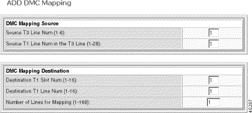
Step 4 Specify DMC mapping as follows:
| Displayed Information | Description |
|---|---|
Source T3 Line Num | The number of the source DS3 line. When mapping more than one DS1 line, other DS3 lines may be mapped. Valid entries are 1 through 6. |
Source T1 Line Num in the T3 Line | The number of the DS1 line, or starting DS1 line, within the DS3 line. Valid entries are 1 through 28. |
Destination T1 Slot Num | The logical slot number for the destination NSC. When mapping more than one DS1 line, other NSC slots may be mapped as well. Valid entries are 1 through 16. |
Destination T1 Line Num | The number of the DS1, or starting DS1, in the NSC. Valid entries are 1 through 16. |
Number Of Lines for Mapping | The number of map pairs to add. Valid entries are 1 through 192, depending on existing mapping. To map a single point, set to 1. |
Step 5 Click Add and confirm you action.
The system creates the specified DS3 to DS1 mapping entries.
To modify entries in the map table, follow these steps:
Step 1 On the Navigation pane, click Line.
Step 2 Click DMC T3-T1 Mapping.
The DMC T3-T1 Mapping screen opens.
Step 3 On the DMC T3-T1 Mapping screen, click the i icon.
The configuration form opens.
Step 4 Update map settings as follows:
| Displayed Information | Description |
|---|---|
Source T3 Line Num | The number of the source DS3 line. When mapping more than one DS1 line, other DS3 lines may be mapped. Valid entries are 1 through 6. |
Source T1 Line Num | The number of the DS1 line, or starting DS1 line, within the DS3 line. Valid entries are 1 through 28. |
Destination T1 Slot Num | The logical slot number for the destination NSC. When mapping more than one DS1 line, other NSC slots may be mapped as well |
Destination T1 Line Num | The number of the DS1, or starting DS1, in the NSC. Valid entries are 1 through 16. |
Step 5 Click Modify.
The system applies the configuration changes.
To delete a single map table entry, follow these steps:
Step 1 On the Navigation pane, click Line.
Step 2 Click DMC T3-T1 Mapping.
The DMC T3-T1 Mapping screen opens.
Step 3 On the DMC T3-T1 Mapping screen, click the - icon for the entry you want to delete.
Step 4 Confirm your action.
The system deletes the map entry.
To delete a range of map table entries, follow these steps:
Step 1 On the Navigation pane, click Line.
Step 2 Click DMC T3-T1 Mapping.
The DMC T3-T1 Mapping screen opens.
Step 3 On the DMC T3-T1 Mapping screen, click the - icon on the top row of icons.
The Delete DMC Mapping form opens.
Step 4 Specify the lines to delete, which the following table describes:
| Displayed Information | Description |
|---|---|
Source T3 Line Num | The number of the source DS3 line. When mapping more than one DS1 line, other DS3 lines may be mapped. Valid entries are 1 through 6. |
Source T1 Line Num | The number of the DS1 line, or starting DS1 line, within the DS3 line. Valid entries are 1 through 28. |
Number Of Lines for Mapping | The number of map pairs to add. Valid entries are 1 through 192, depending on existing mapping. To map a single point, set to 1. |
Step 5 Click Delete and confirm your action.
The system deletes the map entries.
This section describes the procedures for adding and changing Fast Ethernet lines. These procedures apply to SCCs configured with Fast Ethernet hardware. For those systems using the IPDC call control protocol, you can also set up static routes for these lines. For more information, see "Configuring Static Routes".
To view Fast Ethernet line status, follow these steps:
Step 1 On the Navigation pane, click Line.
Step 2 Click Ether.
Step 3 Click All-Lines.
The Ether Line Configuration screen opens.
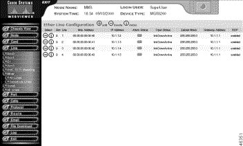
Step 4 Interpret the table as follows:
| Displayed Information | Description |
|---|---|
Slot | The slot number of the SCC with the line |
Line | The line number of the Fast Ethernet line |
MAC Address | The physical address of the line |
IP Address | The IP address for this host |
Alarm Status | The current alarm condition of the line
|
Oper Status | The operational status for the line, as follows:
|
Subnet Mask | The IP subnet mask for this host |
Gateway Address | The primary gateway for this line |
RDP | The Router Discovery Protocol status |
To view selective Fast Ethernet lines, follow these steps:
Step 1 On the Navigation pane, click Ether.
Step 2 Click Selective-Lines.
The selection criteria screen opens.

Step 3 Enter your selection criteria:
| Criteria | Description |
|---|---|
Slot Number | The SCC slot number. Valid entries: 9 or 10. |
Operational Status | The status of the lines you want to view:
|
Step 4 Click Display.
The Ether Line Configuration form opens with Fast Ethernet lines that meet the filter criteria.
To add a Fast Ethernet line, follow these steps:
Step 1 On the Navigation pane, click Line.
Step 2 Click Ether.
Step 3 Click All-Lines.
The Ether Line Configuration screen opens.
Step 4 On the Ether Line Configuration screen, click the + icon.
The Add Ether Line form opens.

Step 5 Specify the line configuration:
| Displayed Information | Description |
|---|---|
Slot | The SCC slot number, either 9 or 10 |
Line | The line number of the Fast Ethernet line to add, from 1 to 4 |
IP Address | The IP address for this host |
Subnet Mask | The IP subnet mask for this host |
Primary Gateway Address | The primary gateway for this line |
Router Discovery Protocol | The Router Discovery Protocol status |
Initial State of the Added Ether Line | The desired operational state for the line |
Duplex Mode | The duplex mode for the line, either full or half |
Step 6 Click Add.
The system adds the line.
 |
Warning Changing a Fast Ethernet line interrupts service to a large number of users. Perform this operation during light traffic periods or in a pre-arranged maintenance window. |
Step 1 On the Navigation pane, click Line.
Step 2 Click Ether.
Step 3 Click All-Lines.
The Ether Line Configuration screen opens.
Step 4 On the Ether Line Configuration screen, click the i icon on the row you want to modify.
The Modify Ether Line Configuration form opens.

The form displays the following read-only values:
| Displayed Information | Description |
|---|---|
Link Alarm Status | The current Fast Ethernet alarm status:
|
Mac Address | The physical address of the line |
IP Address | The IP address for the Fast Ethernet line, expressed in standard IP dot notation |
Operational Status | The operational status:
|
Step 5 Update Fast Ethernet settings as follows:
| Displayed Information | Description |
|---|---|
Slot | The slot number of the SCC, either 9 or 10 |
Line | The Fast Ethernet line number, from 1 to 4 |
Subnet Mask | The subnet mask for this line, expressed in standard IP dot notation |
Primary Gateway Address | The primary IP gateway for this line |
Route Discover Protocol | Enables or disables Router Discovery Protocol:
|
Duplex Mode of the Ether Line Interface | The mode of the line:
|
Step 6 To change the administrative status of the line, click Link Up or Link Down.
Step 7 Click Modify and confirm your action.
The system changes the Fast Ethernet configuration.
You can bring the Fast Ethernet line up or down from the Modify Ether Line Configuration form.
To change Fast Ethernet administrative status, follow these steps:
Step 1 On the Navigation pane, click Ether.
Step 2 Click All-Lines.
The Ether Line Configuration screen opens.
Step 3 On the Ether Line Configuration screen, click the i icon on the row you want to modify.
The Modify Ether Line Configuration form opens:
Step 4 Click Link Up or Link Down, as desired.
Step 5 Click Modify and confirm your action.
To delete a Fast Ethernet line, follow these steps:
Step 1 On the Navigation pane, click Line.
Step 2 Click Ether.
Step 3 Click All-Lines.
The Ether Line Configuration screen opens.
Step 4 On the Ether Line Configuration screen, click the - icon on the line you want to delete.
Step 5 Confirm your action.
The system deletes the Fast Ethernet line.
This section describes the process of configuring static routes for Fast Ethernet lines.
To view all static routes, follow these steps:
Step 1 On the Navigation pane, click Route.
Step 2 Click Static Route Setup.
The Static Route Configuration form opens.

Step 3 Interpret the table as follows:
| Displayed Information | Description |
|---|---|
Dest IP Subnet | The IP address of a remote network with which you want a static route. The last byte of the IP number must be zero. For example, 127.2.4.0 is valid. |
Slot | Slot number for the route entry. |
Line | Line number for the route entry. |
Priority | Priority for the route entry. Priority 1 is the highest and 10 is the lowest, with a default of 1. |
To add a static route, follow these steps:
Step 1 On the Navigation pane, click Route.
Step 2 Click Static Route Setup.
The Static Route Configuration screen opens.
Step 3 On the Static Route Configuration screen, click the + icon.
The Add Static Route Configuration form opens.

Step 4 Specify the static route parameters as follows:
| Displayed Information | Description |
|---|---|
Destination IP Subnet | The IP address of a remote router with which you want a static route. The last byte of the IP number must be zero. For example, 127.2.4.0 is valid. |
Out-bound Slot Number | Slot number for the route entry. |
Out-bound Line Number | Line number for the route entry. |
Priority | Priority for the route entry. Priority 1 is the highest and 10 is the lowest. |
Step 5 Click Add.
The system adds the static route to the routing table.
To delete a static route, follow these steps:
Step 1 On the Navigation pane, click Route.
Step 2 Click Static Route Setup.
The Static Route Configuration screen opens.
Step 3 On the Static Route Configuration screen, click the - icon on the row with the route you want to delete and confirm your action.
The system deletes the static route from the routing table.
This section describes the procedures for adding and changing OC-3 lines. These procedures apply to SCCs configured for OC-3.
To view OC-3 line status, follow these steps:
Step 1 On the Navigation pane, click Line.
Step 2 Click Sonet.
Step 3 Click All-Lines.
The Sonet Line Configuration screen opens.

Step 4 Interpret the table as follows:
| Displayed Information | Description |
|---|---|
Slot | The slot number of the SCC with the line |
Line | The line number of the OC-3 line |
Line Type | The physical medium, either SONET or SDH |
Frame Type | The type of framing, either STS-3c or STM-1 |
Line Status | The current alarm condition of the line
|
Admin Status | The administrative status for the line, always Up |
Support Path E-RDI | The support path for enhanced remote defect indicator, either enabled or disabled |
To add a OC-3 line, follow these steps:
Step 1 On the Navigation pane, click Line.
Step 2 Click Sonet.
Step 3 Click All-Lines.
The Sonet Line Configuration screen opens.
Step 4 Click the + icon.
The Add Sonet Line form opens.

Step 5 Specify the line configuration:
| Displayed Information | Description |
|---|---|
Slot | The SCC slot number, either 9 or 10 |
Line | The line number of the OC-3 line, from 1 to 4 |
Contiguous Creating Lines | The number of contiguous OC-3 lines to add with this configuration, from 1 to 4 |
Medium Type | The type of circuit:
|
Frame Scrambling | The frame scrambling state:
|
Payload Scrambling | The payload scrambling state:
|
Loopback Config | The signal loopback state:
Serial and parallel are both local loopbacks. |
Transmit Clock Source | The clock source for the transmit signal:
|
Support Path ERDI | The state of the ERDI (Enhanced Remote Defect Indication:
|
Path Signal Label | The signal label to transmit in the SONET path overhead:
|
Expected Path Signal Label | The expected signal label from the SONET path overhead:
|
Sonet Path Trace Identifier | The trace identifier to transmit in the SONET path overhead. Value: ASCII string of 2 to 126 hex characters. For more information, see "Understanding E-RDI and Trace Parameters". |
Expected Sonet Path Trace Identifier | The expected trace identifier in the SONET path overhead. Value: ASCII string of 2 to 126 hex characters. |
Step 6 Click Add.
The system adds the specified number of lines.
 |
Warning Changing an OC-3 line interrupts service to a large number of users. Perform this operation during light traffic periods or in a pre-arranged maintenance window. |
Step 1 On the Navigation pane, click Line.
Step 2 Click Sonet.
Step 3 Click All-Lines.
The Sonet Line Configuration screen opens.
Step 4 On the Sonet Line Configuration screen, click the i icon on the row you want to modify.
The Modify Sonet Line Configuration form opens.

The form displays the following read-only values:
| Information | Description |
|---|---|
Interface Type | The type of interface. Fixed at OC-3 |
Current Period Time Elapsed | The elapsed time of the current error-measurement period, expressed in seconds |
Valid Intervals | The number of prior intervals for which valid data was stored |
Circuit Identifier | A text string describing the hardware implementation. |
Line Type | The type of optical fiber, either single mode or multimode depending on the back card installed. |
Line Coding | The data coding scheme of this line. Fixed at sonetMediumOther. |
Step 5 Update OC-3 line settings as follows:
| Displayed Information | Description |
|---|---|
Medium Type | The type of circuit:
|
Admin Status | The administrative status:
|
Frame Type | The type of framing:
|
Frame Scrambling | The frame scrambling state:
|
Payload Scrambling | The payload scrambling state:
|
HCS Scrambling | The HCS scrambling state (reserved for future use) |
Loopback Config | The signal loopback state:
|
Transmit Clock Source | The clock source for the transmit signal:
|
Support Path ERDI | The state of the ERDI (Enhanced Remote Defect Indication:
|
Path Signal Label | The signal label to transmit in the SONET path overhead:
|
Expected Path Signal Label | The expected signal label from the SONET path overhead:
|
Received Sonet Path Signal Label | The signal label received on this line |
Sonet Path Trace Identifier | The trace identifier to transmit in the SONET path overhead. Value: ASCII string of 2 to 126 hex characters. For more information, see "Understanding E-RDI and Trace Parameters". |
Expected Sonet Path Trace Identifier | The expected trace identifier in the SONET path overhead. Value: ASCII string of 2 to 126 hex characters. |
Received Sonet Path Trace Identifier | The path trace identifier received on this line |
Step 6 Click Modify and confirm your action.
The system changes the OC-3 configuration.
To delete a OC-3 line, follow these steps:
Step 1 On the Navigation pane, click Line.
Step 2 Click Sonet.
Step 3 Click All-Lines.
The Sonet Line Configuration screen opens.
Step 4 On the Sonet Line Configuration screen, click the - icon on the line you want to delete.
Step 5 Confirm your action.
The system deletes the OC-3 line.
Path and trace labels help identify particular SONET line. The trace label is a text string carried in a 16-byte or 32-byte message carried in the SONET overhead. The system alters or reserves some of the bytes for synchronization or other purposes.
When using 16-byte messages, consider the following points:
You use two hexidecimal numbers to represent each ASCII character in a trace message. For example, you represent an ASCII space with the hex pair 20. The following table shows a few additional examples.
| Trace Message | Hex String |
|---|---|
4 | 34 |
Hello World | 48656c6c6f20576f726c64 |
For 16-byte msg, the maximum input string size is 32 hex characters. For a64-byte message, you can specify up to 62 characters for a total of 124 hex characters. Refer to the following conversion table to map hex pairs to ASCII characters.
00 NUL | 01 SOH | 02 STX | 03 ETX | 04 EOT | 05 ENQ | 06 ACK | 07 BEL |
|---|---|---|---|---|---|---|---|
08 BS | 09 HT | 0A NL | 0B VT | 0C NP | 0D CR | 0E SO | 0F SI |
10 DLE | 11 DC1 | 12 DC2 | 13 DC3 | 14 DC4 | 15 NAK | 16 SYN | 17 ETB |
18 CAN | 19 EM | 1A SUB | 1B ESC | 1C FS | 1D GS | 1E RS | 1F US |
20 SP | 21 ! | 22 dq | 23 # | 24 $ | 25 % | 26 & | 27 ' |
28 ( | 29 ) | 2A * | 2B + | 2C , | 2D - | 2E . | 2F / |
30 0 | 31 1 | 32 2 | 33 3 | 34 4 | 35 5 | 36 6 | 37 7 |
38 8 | 39 9 | 3A : | 3B ; | 3C < | 3D = | 3E > | 3F ? |
40 @ | 41 A | 42 B | 43 C | 44 D | 45 E | 46 F | 47 G |
48 H | 49 I | 4A J | 4B K | 4C L | 4D M | 4E N | 4F O |
50 P | 51 Q | 52 R | 53 S | 54 T | 55 U | 56 V | 57 W |
58 X | 59 Y | 5A Z | 5B [ | 5C \ | 5D ] | 5E ^ | 5F _ |
60 \Q | 61 a | 62 b | 63 c | 64 d | 65 e | 66 f | 67 g |
68 h | 69 i | 6A j | 6B k | 6C l | 6D m | 6E n | 6F o |
70 p | 71 q | 72 r | 73 s | 74 t | 75 u | 76 v | 77 w |
78 x | 79 y | 7A z | 7B { | 7C | | 7D } | 7E ~ | 7F DEL |
The system takes the following actions on error on malformed hex strings:
To view a summary of all lines, follow these steps
Step 1 On the Navigation pane, click Line.
Step 2 Click All Lines.
Step 3 Click the All-Lines submenu item.
The Common Line screen opens.

Step 4 Interpret the table as follows:
| Displayed Information | Description |
|---|---|
Slot | The slot number of the line |
Line | The line number |
Line Type | The type of line |
Step 5 To view line information, click the i icon.
Step 6 To view counter information, click the C icon.
To view selected lines, follow these steps:
Step 1 On the Navigation pane, click All-Lines.
Step 2 Click Selective-Lines.
The following form opens.

Step 3 Enter the line filter criteria:
| Displayed Information | Description |
|---|---|
Slot Number | The desired slot number. Valid settings are 1-16 and all. |
Line Type | The type of line:
|
Step 4 Click Display.
The Common Line screen opens with the filter criteria applied.
See the following sections for port configuration tasks.
Voice ports use voice over IP or ATM. Voice ports identify the physical location and characteristics of a voice interface at a DS0 level. You add PVC (Permanent Virtual Circuit) end points to MGX 8260 nodes using a NMS (Network Management System). A MGC manages SVC (Switched Virtual Circuit) end points and connections.
The MGX 8260 Media Gateway identifies a voice port by a logical port number that is independent of the port's physical location. The following parameters describe the physical location:
When you add or change a voice port, you associate a logical port number with these physical descriptors.
This section describes the procedure for viewing, adding, or changing voice ports.
To view voice port status, follow these steps:
Step 1 On the Navigation pane, click Port.
Step 2 Click Voice.
Step 3 Click All Ports.
The Voice Port Configuration screen opens.

Step 4 Interpret the table as follows:
| Displayed Information | Description |
|---|---|
Slot | The logical slot number of the NSC associated with the port |
Port | The logical port number assigned to the port |
Line Num | The number of the DS1/E1 line associated with the DS0 voice line |
DS0 Num | The number of the DS0 channel for the voice port |
Dyna Dejitter | The status of the dejitter buffer, either enabled or disabled |
Dejr Buf Len | The initial length of the dejitter buffer, specified in multiples of 10 msec. |
PkLoad Time | The IP packet loading time for voice service, expressed in multiples of 10 msec |
Echo Tail | The length of the echo cancel tail |
Oper Status | The operating status of the voice port, as follows:
|
Max Buf Len | The maximum length of the dejitter buffer, specified in multiples of 10 msec. |
Min Buf Len | The minimum length of the dejitter buffer, specified in multiples of 10 msec. |
To view selected ports, follow these steps:
Step 1 On the Navigation pane, click Port.
Step 2 Click Voice.
Step 3 Click Selective-Ports.
The following form opens.

Step 4 Enter the voice selection criteria:
| Displayed Information | Description |
|---|---|
Slot Number | The desired slot number. Valid settings are 1-16 and all. |
Port Status | The port status:
|
Line Number | The desired line number. Valid settings are 1-16 and all. |
Step 5 Click Display.
The Voice Port Configuration screen opens, displaying the ports that meet the selection criteria.
To add a voice port, follow these steps:
Step 1 On the Navigation pane, click Port.
Step 2 Click Voice.
Step 3 Click All Ports.
The Voice Port Configuration screen opens.
Step 4 On the Voice Port Configuration screen, click the + icon.
The Add Voice Port form opens.
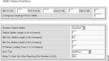
Step 5 Specify the port configuration:
| Displayed Information | Description |
|---|---|
Slot | The logical slot number of the NSC associated with the port. Values 1 to 16. |
Port | The logical port number assigned to the port. Values: 1 to 512. |
Line | The number of the DS1/E1 line for the voice port. Valid settings are 1 through 16. |
DS0 | The number of the DS0 channel for the voice port. Values: 1 to 24 for DS1 and 1 to 30 for E1. |
Contiguous Creating Ports | The number of contiguous ports to create. Values: 1 to 6944 |
Dynamic Dejitter Buffer | The status of the dejitter buffer, either enabled or disabled. Default = disabled. |
Dejitter Buffer Length | The initial length of the dejitter buffer, specified in multiples of 10 msec. Default = 2. |
Max Dej. Buffer Length | The maximum length of the dejitter buffer, specified in multiples of 10 msec. Default = 50. |
Min Dej. Buffer Length | The minimum length of the dejitter buffer, specified in multiples of 10 msec. Default = 1. |
IP Packet Loading Time | The IP packet loading time for voice service, expressed in multiples of 10 msec. Default = 1. |
Echo Tail | The length of the echo cancel tail: 1 = echo disabled 2 = tail24ms— 24 msecs 3 = tail32ms—32 msecs 4 = tail48ms— 48 msecs 5 = tail64ms—64 msecs (default) 6 = tail80ms—80 msecs 6 = tail96ms— 96 msecs 7 = tail112ms—112 msecs 8 = tail128ms—128 msecs |
Wrap To Next Slot After Reaching Port Number | The port number at which to wrap to the next slot. Set to the maximum number of DS0s for NSCs in your configuration. For DS1uses 384 and for E1 use 480 with CAS or 496 without CAS. Values: 1 to 512 |
Step 6 Click Add.
The system adds the port.
To change the configuration of a voice port, follow these steps:
Step 1 On the Navigation pane, click Port.
Step 2 Click Voice.
Step 3 Click All Ports.
The Voice Port Configuration screen opens.
Step 4 On the Voice Port Configuration screen, click the I icon on the row with the port you want to modify.
The Modify Voice Port Configuration form opens.

The form displays the following read-only information:
| Displayed Information | Description |
|---|---|
Operation Status | The operating status of the voice port, as follows:
|
Step 5 Update the voice port parameters. For parameter definitions, see Adding Voice Ports
Step 6 Click Modify and confirm your action.
The system applies the configuration changes.
To delete a single voice port, follow these steps:
Step 1 On the Navigation pane, click Port.
Step 2 Click Voice.
Step 3 Click All Ports.
The Voice Port Configuration screen opens.
Step 4 On the Voice Port screen, click the - icon for the port you want to delete.
Step 5 Confirm your action.
The system deletes the voice port.
To delete a range of voice ports, follow these steps:
Step 1 On the Navigation pane, click Port.
Step 2 Click Voice.
Step 3 Click All Ports.
The Voice Port Configuration screen opens.
Step 4 On the Voice Port screen, click the - icon on the top row of icons.
The Delete Voice Ports form opens.
Step 5 Specify the ports as follows:
| Displayed Information | Description |
|---|---|
Slot | The logical slot number of an NSC |
Port | The logical port number for the new port |
Contiguous Deleting Ports | The number of contiguous ports to delete |
Wrap to Next Slot After Reaching Port Number | The port number at which to wrap to the next slot. Set to the maximum number of DS0s for NSCs in your configuration. For DS1uses 384 and for E1 use 480 with CAS or 496 without CAS. Values: 1 to 512 |
Step 6 Click Delete and confirm your action.
The system deletes the voice port.
To view information on all ports, follow these steps:
Step 1 On the Navigation pane, click Port.
Step 2 Click All Ports.
The Common Port screen opens.
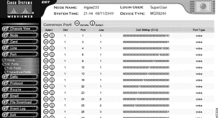
Step 3 Interpret the common port table as follows:
| Displayed Information | Description |
|---|---|
Slot | The slot hosting the port |
Port | The common logical port number |
Line | The common physical line number for this port |
DS0 Bit Map | Common DS0 bit map for this port. A 1 indicates the DS0 position in the DS1/E1 line for this port |
Port Type | The port type: Voice |
Step 4 To view port information, click the I icon.
Step 5 To delete a port, click the - icon on the row with the port you want to delete and confirm your action.
To view selected ports, follow these steps:
Step 1 On the Navigation pane, click Port.
Step 2 Click Selective-Ports.
The following form opens.

Step 3 Enter the line filter criteria as follows:
| Criteria | Description |
|---|---|
Slot Number | The desired slot number. Valid settings are 1-16 and all |
Port Type | The port type:
|
Line Number | The line number. Valid settings are 1-16 and all |
Step 4 Click Display. The Common Port screen opens with the filter criteria applied.
Active call information is useful for audits or trouble analysis.The MGX 8260 displays active calls as follows
To view active voice calls by resource, follow these steps:
Step 1 On the Navigation pane, click Calls.
Step 2 Click Physical Calls.
Step 3 Click All-Calls.
The Active Call Physical Table screen opens.
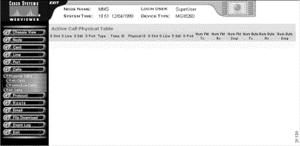
Step 4 Interpret the table as follows:
| Displayed Information | Description |
|---|---|
S Slot | The slot number for the active call source. The slot, line, and DS0 numbers uniquely define a call while it is active. |
S Line | The line number for the active call source. |
S Ds0 | The DS0 number for the active call source. |
S Port | The logical port number for the active call source. |
Type | A value that identifies the call type: 1: Voice over IP 2: Time division multiplex |
Trans. ID | The transaction identifier for the active call. Only the backend platform software uses this number |
Physical ID | An identifier for the active call. |
D Slot | The slot number for the active call destination. |
D Line | The line number for the active call destination. |
D Ds0 | The DS0 number for the active call destination. |
D Port | The logical port number for the active call destination. |
Num Pkt Tx | The number of packets transmitted since call setup |
Num Pkt Rx | The number of packets received since call setup |
Num Pkt Drop | The number of packets dropped since call setup |
Num Byte Tx | The number of bytes transmitted since call setup |
Num Byte Rx | The number of bytes received since call setup |
Num Byte Drop | The number of bytes dropped since call setup |
To view selected ports, follow these steps:
Step 1 On the Navigation pane, click Calls.
Step 2 Click Physical Calls.
Step 3 Click Selective-Calls.
The following form opens.

Step 4 Enter the voice selection criteria:
| Displayed Information | Description |
|---|---|
Slot Number | The desired slot number. Valid settings are 1-16 and all. |
Line Number | The desired line number. Valid settings are 1-16 and all. |
Call Type | The type of call. Valid settings are voip, tdm, and all. |
Step 5 Click Display.
The Active Call Physical Table screen opens, displaying the calls that meet the selection criteria.
To view active voice calls by transaction, follow these steps:
Step 1 On the Navigation pane, click Calls.
Step 2 On the Calls submenu, click All Calls.
Step 3 On the All Calls submenu, click All-Calls.
The Active Call Physical Table screen opens.

Step 4 Interpret the table as follows:
| Displayed Information | Description |
|---|---|
Trans ID | The transaction identifier for the active call. Only the backend platform software uses this number |
Call ID | An identifier for the active call. |
S Slot | The slot number for the active call source. The slot, line, and DS0 numbers uniquely define a call while it is active. |
S Line | The line number for the active call source. |
S Ds0 | The DS0 number for the active call source. |
S Port | The logical port number for the active call source. |
Type | A value that identifies the call type: 1: Voice over IP 2: Time division multiplex |
D Slot | The slot number for the active call destination. |
D Line | The line number for the active call destination. |
D Ds0 | The DS0 number for the active call destination. |
D Port | The logical port number for the active call destination. |
Num Pkt Tx | The number of packets transmitted since call setup |
Num Pkt Rx | The number of packets received since call setup |
Num Pkt Drop | The number of packets dropped since call setup |
Num Byte Tx | The number of bytes transmitted since call setup |
Num Byte Rx | The number of bytes received since call setup |
Num Byte Drop | The number of bytes dropped since call setup |
![]()
![]()
![]()
![]()
![]()
![]()
![]()
![]()
Posted: Mon Nov 25 11:04:08 PST 2002
Copyright 1989-2000©Cisco Systems Inc.