An integrated alarm value for this card. For the SCC and BSC cards, the 10 indicators show the following alarm states:
Indicator 1: integrated line alarm
Indicator 2: line performance alarm
Indicator 3: integrated port alarm
Indicator 4: integrated end point alarm
Indicator 5: EMM temperature alarm
Indicator 6: EMM voltage alarm
Indicator 7:software error alarm
Indicator 8: component failure alarm
Indicator 9: PLCP statistical alarm state
Indicator 10: PLCP alarm state
For the NSC and DMC cards, the indicators show the following alarm states:
Indicator 1: integrated line alarm
Indicator 2: line performance alarm
Indicator 3: integrated port alarm
Indicator 4: integrated end point alarm
Indicator 5: EMM temperature alarm
Indicator 6: EMM voltage alarm
Indicator 7: software error alarm
Indicator 8: component failure alarm
Read the indicators from right to left.
Fr Card
The front card type, as follows:
dmc—Distribution Matrix Card
nsc—Narrowband Service Card
scc—Switch Control Card 5Gbps
bsc—Broadband Service Card
Bk Card
The back card type, as follows:
scc-4fe—Switch Control Card with four Fast Ethernet (100 Mbps) ports
scc4OC3—Switch Control Card with four OC-3 ports
scc4OC3MM—Switch Control Card with four mulit-mode OC-3 ports
bsc12T3—Broadband Service Card with 12 DS3 ports
dmcBsc6t3—Distribution Matrix Card or BSC with six DS3 ports
nsc-16t1e1—Narrowband Service Card with sixteen T1 ports
rnd16-t1e1—Redundancy backcard for NSC
blank—No back card
Dgtr Crd1
The type of daughter card installed on the NSC or SCC card, as follows:
NSC types:
msmDSP—Multiservice module DSP
msmDSPV—Multiservice module DSP voice
SCC type:
bim4FE—Broadband Interface Module with four Fast Ethernet ports
bim4OC3ATM—Broadband Interface Module with 4 OC-3 ATM ports
Dgtr Crd2
The type of secondary daughter card installed. See Dgtr Crd1 types.
Configuring Card Parameters
To view or change card parameters, follow these steps:
Step 1 On the Navigation pane, click Card.
Step 2 Click All-Cards. The Physical Slot Configuration screen opens.
Step 3 Click the i icon on the row of the card you want to view.
The system displays the Physical Slot Alarm Status and Configuration screen, which contains two panes, a Alarm Status pane and a configuration pane (only the latter is shown below).
The following table describes the read-only fields:
Displayed Information
Description
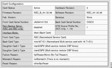
Card Status
The status of the card, as follows:
empty
in-boot
active
standby
mismatch
failed
Firmware Revision
The firmware revision of the card
Fab Version
The fab version of the card
Front Card Serial Number
The serial number of the front card
Ram Backup Setup
The status of RAM backup facility. Click Ram Backup Setup and select the mode, as follows
Enabled
Disabled.
Interface Mode
The interface mode for an NSC. Click Interface Mode and select the mode, as follows:
The reason for the mismatch for the card, as follows:
noMismatch
configMismatchHw—configuration file and hardware do not match
fcAndBcMismatch—the front and back card do not match
daughterCardBcMismatch—the daughter card and back card do not match
peerHardWareMismatch—the two SCC cards do not match
dmcMismatch—DMC configuration mismatch with the hardware
noBackCard—No backcard
noDaughterCard—None or invalid daughter cards
Reset Reason
The reason the card was last reset, as follows:
shellReset
hardReboot
softRebootNoImage
softReboot
chipError
eventLogReset
taskError
softwareUpgrade
gracefulSwitchover
dmcRemovedSwitchover
sccBcRemovedSwitchover
appsInitFailed
plfmTimerExpired
ideReformat,
unknownResetReason
Hardware Revision
The hardware revision of the card
Software Revision
The software revision of the card
Services
The services offered by the card:
ATM
Frame Relay (reserved for future use)
Voice
IP Emulation (reserved for future use)
Back Card Serial Number
The serial number of the back card
ATM Queue Profile
The queue profile for ATM traffic on the SCC. Valid profiles: 1 to 10
Step 4 Click Modify and confirm your action.
Step 5 Click Modify to apply your changes.
Configuring Redundancy
The MGX 8260 Media Gateway supports both redundant and non-redundant operation for all cards. With redundancy, the system switches to a protection card if an active card fails.The SCC and DMC don't require user setup for redundant operation; when you have two cards installed they automatically protect each other. To configure redundancy for the NSC or BSC, you define protection pairs. The Cisco MGX 8260 uses 1:N protection for NSCs and 1:1 protection for BSCs.
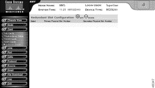
Viewing Redundancy Pairs
To view redundancy pairs, follow these steps:
Step 1 On the Navigation pane, click Card.
Step 2 Click Redundancy Setup.
The Redundant Slot Configuration screen opens.
Displayed Information
Description
Primary Physical Slot Number
The physical slot for the primary card of the redundancy pair. This slot is active during normal operation.
Secondary Physical Slot Number
The physical slot for the secondary card of the redundancy pair. This slot is in standby during normal operation and protects the primary slot in the event of a primary failure.
Defining Redundant Cards
There are three possible redundancy scenarios:
BSC redundancy
This scenario uses pairs of BSCs configured for 1:1 redundancy.
NSC redundancy without DMC
This scenario requires a redundant back card in the protection NSC slot.
NSC redundancy with DMC
This scenario does not require, and cannot have, a redundant back card.
Adding BSC Redundancy
In order to successfully configure a redundant pair, the following conditions must be true:
The hardware configuration of the two BSCs must be identical
The firmware version of the two BSCs must be identical
The redundant BSC must not have any lines configured
Warning Adding card redundancy interrupts service. Perform this operation during light traffic periods or in a pre-arranged maintenance window.
To configure BSC redundancy, follow these steps:
Step 1 Install a redundant BSC. You can use any available slot from 11 to 16.
Step 2 Add a redundant "Y" cable between all ports on the two cards.
Step 3 Click Cards on the navigation pane, then click Redundancy Setup.
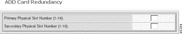
Step 4 On the Redundant Slot Configuration screen, click the + icon.
The Add Card Redundancy form opens.
Step 5 Specify the redundancy pair.
Displayed Information
Description
Primary Physical Slot Number
The physical slot for the primary card of the redundancy pair. This slot is active during normal operation.
Secondary Physical Slot Number
The physical slot for the secondary card of the redundancy pair. This slot is in standby during normal operation and protects the primary slot in the event of a primary failure.
Step 6 Click Add.
Both cards reboot and initialize for redundancy.
Step 7 Return to the Redundant Slot Configuration screen to verify the configuration.
Configuring NSC Redundancy without DMC
To configure NSC redundancy without DMC, follow these steps:
Step 1 Verify that the redundant NSC has a redundancy back card installed and that it is in the standby state. For more information, including the procedure, see the "Configuring Card Parameters" section.
Step 2 Verify that each primary NSC has a T1/E1 back card and is in the active state. For more information, including the procedure, see the "Viewing Card Status" section.
Step 3 Click Cards on the navigation pane, then click Redundancy Setup.
Step 4 On the Redundant Slot Configuration screen, click the + icon.
The Add Card Redundancy form opens:
Step 5 Specify the primary and secondary cards.
Step 6 Click Add.
Both cards reboot and initialize for redundancy.
Step 7 Return to the Redundant Slot Configuration screen to verify the configuration.
Step 8 Configure other redundancy pairs, as necessary. All pairs use the same secondary card.
Configuring NSC Redundancy with DMC
To configure NSC redundancy with DMC, follow these steps:
Step 1 Verify that at least one DMC and DS3 back card is installed in physical slot seven or eight. For the procedure, see the "Viewing Card Status" section.
Step 2 Check the Card Configuration screen to verify that the redundant NSC does not have a redundancy back card installed.
Step 3 Check the Card Configuration screen to verify that each primary NSC does not have a back card and is in the active state.
Step 4 Click Cards on the navigation pane, then click Redundancy Setup.
Step 5 On the Redundant Slot Configuration screen, click the + icon.
The Add Card Redundancy form opens.
Step 6 Specify the primary and secondary cards.
Step 7 Click Add. Both cards reboot and initialize for redundancy.
Step 8 Return to the Redundant Slot Configuration screen to verify the configuration.
Deleting Redundancy
To delete redundancy, follow these steps:
Step 1 Click Cards on the navigation pane.
Step 2 Click Redundancy Setup.
The Redundant Slot Configuration screen opens.
Step 3 Click the - icon on the row with the redundancy pair you want to delete and confirm you action.
The system deletes the redundancy pair and updates the redundancy table.
Invoking a Switchback
The switchover from primary to secondary cards is automatic when a primary card fails. After repairing the failure that caused a switchover, you must manually switch the protection pair back to their original state.
To force a redundancy switchover, follow these steps:
Step 1 On the Navigation pane, click Card.
Step 2 Click All-Cards.
The Physical Slot Configuration screen opens.
Step 3 Click the S icon on the row of the desired card. The system forces a protection switch.
Viewing MSM Configuration
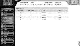
To view MSM type and operational status, follow these steps:
Step 1 On the Navigation pane, click Card.
Step 2 Click MSM-Cards.
The MSM Card screen opens:
Step 3 Interpret the display as follows:
Displayed Information
Description
Slot Number
The physical slot of the card hosting the MSM
MSM Number
The number of the MSM on the host card
Type
The type of MSM:
msm-DSP—Multiservice module DSP
msm-CES—Multiservice module circuit emulation service
msm-HDLC—Multiservice module HDLC
Status
The operational status of the MSM:
active
standby
failed
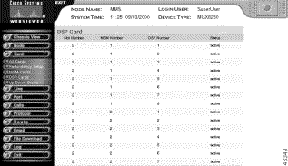
Viewing DSP Configuration
To view MSM type and operational status, follow these steps: