|
|

The MGX 8260 Media Gateway notifies maintenance or operations personnel about equipment alarms at several levels:
You can view the event log for informational notices about changes in the system. For example, inserting a new card adds an event to the log.
The WebViewer displays the most severe alarm in the upper right corner of every screen (see Figure 6-1).
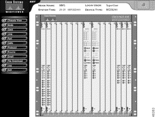
The alarm indicator is a rectangular icon that is green for normal operation and flashes red or yellow for alarm conditions.
You can obtain more information about the alarm by clicking the alarm indicator. The chassis view also shows a graphical representation of the front panel, including alarm indications for each card. To obtain more information about a specific card, click the corresponding Card or Line indicator.
To respond to alarms, you monitor the following sources:
When checking alarms, start with the Alarm Status screen and then use the Navigation pane or hyperlinks to obtain details about the event or condition of interest.
To view alarm status, follow these steps:
Step 1 On the upper right corner of any screen, click the Alarm icon. Alternatively, click Node and then click Alarm on the Navigation pane.
The Alarm Status screen opens.

Operational status is displayed as rows of color-coded indicators. Interpret the color as follows:
Step 2 To obtain more information about all shelf or card EMM alarms, click the i icon above the Shelf Alarm pane or Logical Card Alarm pane.
Step 3 To obtain more information about a specific shelf or card alarm, click the hyperlink above the indicator.
Step 4 To interpret the shelf alarm screens, see the "Environmental Alarms" section. To interpret card alarm card screens, see "Card Alarms" section.
Card alarms provide information on card operation and events.
To view card alarms, follow these steps:
Step 1 On the Navigation pane, click Card.
Step 2 Click All-Cards. Alternatively, click the desired card hyperlink on the Alarm State screen.
The Physical Slot Configuration form opens.
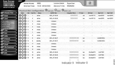
Card alarms are displayed as rows of indicators in the Integrated Alarm column.
Step 3 Interpret the color as follows:
Interpret the alarm indicators for this card as follows:
| Indicator | SCC and BSC | NSC, and DMC |
|---|---|---|
0 | integrated line alarm | integrated line alarm |
1 | line performance alarm | line performance alarm |
2 | integrated port alarm | integrated port alarm |
3 | integrated end point alarm | integrated end point alarm |
4 | EMM temperature alarm | EMM temperature alarm |
5 | EMM voltage alarm | EMM voltage alarm |
6 | software error alarm | software error alarm |
7 | component failure alarm | component failure alarm |
8 | PLCP statistical alarm state | — |
9 | PLCP alarm state | — |
 |
Note Read the indicators from right to left. |
You can open the Logical Card Alarm Status and Configuration form for individual cards three ways:
To view card alarm details, follow these steps:
Step 1 On the Navigation pane, click Card.
Step 2 Click All-Cards.
The Physical Slot Configuration form opens.
Step 3 Click the i icon on the row with the desired card.
The Physical Slot Alarm Status and Configuration form opens, which contains an alarm pane. The following is a typical card alarm pane.

Operational status is displayed as color-coded indicators.
Step 4 Interpret the color as follows:
Step 5 The alarms vary by card. Interpret the appropriate alarms as follows:
| Alarm | Interpretation |
|---|---|
Integrated Line Alarm | Indicates the most severe alarm for the active lines on this card. To view more line alarm information, click the Integrated Line Alarm link. |
Line Performance Alarm | Indicates the most severe performance alarm for active lines on this card. To view more line performance alarm information, click the Line Performance Alarm link. |
Integrated Port Alarm | Indicates the most severe alarm for the active ports on this card. |
Integrated End Point Alarm | Indicates the most severe end point alarm for this card. |
EMM Temperature Alarm | Indicates the most severe alarm from the temperature sensors on the board. To view more EMM information, click the EMM Temperature Alarm link. For more information, see the "Environmental Alarms" section. |
EMM Voltage Alarm | Indicates the most severe alarm from the voltage sensors on the board. To view more EMM information, click the EMM Voltage Alarm link. For more information, see "Environmental Alarms" section. |
Software Error Alarm | Indicates a software error on this card. |
Component Failure Alarm | Indicates a hardware failure on this card. |
To clear the alarm history, set the Clear Alarm History field to Yes and click Modify.
The MGX 8260 Media Gateway groups alarm and performance information as follows:
In addition to viewing alarms and statistics, you can set thresholds for performance alarms.
To view DS1 alarms, follow these steps:
Step 1 On the Navigation pane, click Line.
Step 2 Click Dsx1-T1.
Step 3 Click All-Lines.
The Dsx1-T1 Line Configuration form opens.

DS1 alarms are displayed as rows of indicators in the Line Status column.
Step 4 Interpret the color as follows:
Step 5 Interpret the Line Status alarm display (the DS1 line status) that is displayed as a row of indicators as follows:
|
Note Read the indicators from right to left. |
You can open the Dsx1-T1 Line Status and Configuration screen for an individual line two ways:
To view line alarms for individual DS1 lines, follow these steps:
Step 1 On the Navigation pane, click Line.
Step 2 Click Dsx1-T1.
Step 3 Click All-Lines.
The Dsx1-T1 Line Configuration screen opens.
Step 4 Click the i icon on the row with the desired line.
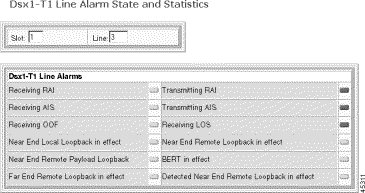
The Dsx1-T1 Line Status and Configuration forms opens with the following alarm pane.

Operational status is displayed as color-coded indicators.
Step 5 Interpret the color as follows:
Step 6 Interpret the alarms as follows:
| Alarm | Description |
|---|---|
Far End LOF | Far end receiving Yellow Alarm |
Far End Sending AIS | Near end receiving AIS |
Near End Loss of Frame | Near end receiving Red alarm |
Near End Is Looped | Near end loopback is active |
Far End Sending TS16 LOMF | Near end sending Loss of Signaling Multiframe Indication (E1 only) |
Near End Detects a Test Code | Near end detects a test code (DS1 only) |
Near End Sending LOF Indication | Near end sending loss of frame |
Near End Sending AIS | Near end sending alarm indication signal |
Near End Loss of Signal | Near end detected loss of signal |
E1 TS16 AIS | Near end receiving Time Slot 16 AIS (E1 only) |
Near End Sending TS16 LOMF | Near End sending Loss of Signaling Multiframe Indication (E1 only) |
Any Other Line Status | Other DS1/E1 failure |
Far End sending Remote Multiframe Alarm Indication | Far End sending Remote Multiframe Alarm Indication |
Near End Sending Remote Multiframe Alarm Indication | Near End Sending Remote Multiframe Alarm Indication |
Far End sending LOMF | Far End sending Loss of Multiframe |
LED Status | The color of the front panel LED |
Line Status | The line status, either up or down |
This section describes changing the configuration settings for alarm severity, integration period, and thresholds for various error conditions, such as LCV, LES, and LSES. The performance alarm is set if the DS1 errors exceed any of the threshold counts.
To change alarm threshold values, follow these steps.
Step 1 On the Navigation pane, click Line.
Step 2 Click Dsx1-T1.
Step 3 Click All-Lines.
The Dsx1-T1 Line Configuration screen opens.
Step 4 On the Dsx1-T1 Line Configuration screen, click the A icon on the row with the desired line.
The Dsx1-T1 Line Alarm Configuration form opens.
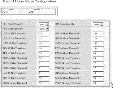
The current slot and line number are displayed at the top.
Step 5 Set the thresholds as follows:
| Threshold | Setting |
|---|---|
Red Alarm Severity | The near end LOF indication:
|
RAI Alarm Severity | The remote alarm indication:
|
Perf. Alarm Severity | The performance alarm indication. minor (fixed) major |
Threshold counters | The thresholds for line errors that invoke a performance alarm. |
Refer to the following table for a list of threshold counters and default values:
Step 6 Click Modify.
The system applies the new thresholds.
To view DS1 counters and performance alarms, follow these steps:
Step 1 On the Navigation pane, click Line.
Step 2 Click Dsx1-T1.
Step 3 Click All-Lines.
The Dsx1-T1 Line Configuration screen opens.
Step 4 On the Dsx1-T1 Line Configuration screen, click the C icon on the row with the desired line.
The Dsx1-T1 Line Alarm State and Statistics forms open.
Alarm status is displayed as color-coded indicators.
Step 5 Interpret the color as follows:
Step 6 Interpret the alarm and counter panes as follows:
| Pane | Interpretation |
|---|---|
DSX1-T1 Line Alarms pane | This group of indicators display DS1 alarms and current test conditions. For more information, see "Viewing Alarms for Individual DS1 Lines" section. |
DSX1-T1 Line Performance Alarms pane | This group of indicators show the performance alarm thresholds this line has exceeded. For more information, see Table 6-1. |
DSX1-T1 Line Statistics | This group shows statistics for LOS, OOF, RAI, and FPE Detected. |
To reset the counters, select the desired counter in the Reset Dsx-T1 Line Counter Type field and click the Reset Counter button on the bottom of the screen.
To view DS1 real-time statistics, follow these steps:
Step 1 On the Navigation pane, click Line.
Step 2 Click Dsx1-T1.
Step 3 Click Counters and Alarm.
The T1 Line Counters/Alarm screen opens.
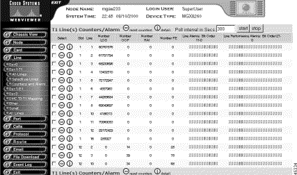
Step 4 Interpret the table as follows:
| Displayed Information | Description |
|---|---|
Slot | The slot hosting this line |
Line | The DS1 line number for these statistics |
Number LOS | The number of times Loss of Signal was detected, with or without integrating to a LOS alarm |
Number OOF | The number of times d Out of Frame was detected, with or without integrating to a OOF alarm |
Number RAI | The number of times Yellow alarm was detected, with or without integrating to a RAI alarm |
Number FE | The number of framing pattern errors per second encountered by the DS1 interface |
Line Alarms | The DS1 line alarms, displayed as a row of indicators.
|
Line Performance Alarms | The DS1 line performance alarms, displayed as a row of indicators.
|
To clear the counters, click the - icon on the row with the desired line. To view more alarm information, click the i icon on the row with the desired line. See the "Viewing DS1 Performance Alarms" section. To filter the display, click the check box for rows you want to display. The display updates on the next poll.
To change the polling interval, follow these steps:
Step 1 Set the Poll Interval in Secs field.
Step 2 Click Start to restart the interval.
Step 3 Click Stop to stop polling.
Interval statistics are collected by each interface for the previous 24 hours of operation. The 24 hours are broken into 96 15-minute intervals. As time progresses, the system drops the oldest interval and adds the latest one, creating a sliding 24-hour window that moves with time.
To view interval DS1 statistics, follow these steps:
Step 1 On the Navigation pane, click Line.
Step 2 Click Dsx1-T1.
Step 3 Click All-Lines.
The Dsx1-T1 Line Configuration screen opens.
Step 4 Click the P icon on the row with the desired line.
The Dsx1-T1 Line Performance Statistics screen opens.
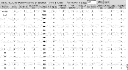
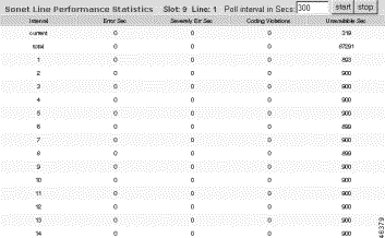
Step 5 Interpret the table as follows:
| Displayed Information | Description |
|---|---|
Interval | The 15 minute interval for the statistics. The Total interval lists statistics for the past 24 hours |
Err Sec | The number of errored seconds |
Sev Err Sec | The number of severely errored seconds |
Sev Err Frm Sec | The number of severely errored frame seconds |
Unavl Sec | The number of unavailable seconds |
Cntl Slip Sec | The number of seconds with timing slips |
Path Code Violation | The number of seconds with path code violations |
Path SEF/AIS | The number of path alarm indication seconds |
Bursty Err Sec | The number of seconds with burst errors |
Line Err Sec | The number of seconds with line errors |
Line Sev Err Sec | The number of line severely errored seconds |
Line Code Violation | The number of line code violations |
Degraded Min | The number of minutes with degraded performance |
To change the polling interval, follow these steps:
Step 1 Set the Poll Interval in Secs field.
Step 2 Click Start to restart the interval.
The MGX 8260 Media Gateway groups alarm and performance information as follows:
In addition to viewing alarms and statistics, you can set thresholds for performance alarms.
To view E1 alarms, follow these steps:
Step 1 On the Navigation pane, click Line.
Step 2 Click E1.
Step 3 Click All-Lines.
The E1 Line Configuration form opens.
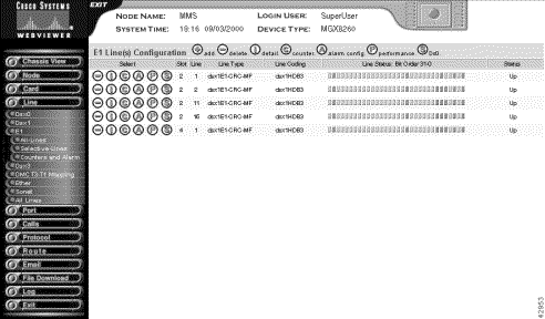
E1 alarms are displayed as rows of indicators in the Line Status column. Interpret the alarm indicator colors as follows:
Step 4 Interpret the Line Status alarm display (the E1 line status) that is displayed as a row of indicators as follows:
|
Note Read the indicators from right to left. |
You can open the E1 Line Status and Configuration screen for an individual line two ways:
To view line alarms for individual E1 lines, follow these steps:
Step 1 On the Navigation pane, click Line.
Step 2 Click E1.
Step 3 Click All-Lines.
The E1 Line Configuration screen opens.
Step 4 On the E1 Line Configuration screen, click the i icon on the row with the desired line.
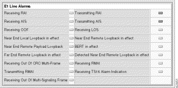
The E1 Line Status and Configuration form opens with the following alarm pane:
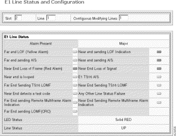
Operational status is displayed as color-coded indicators with the following meaning:
Step 5 Interpret the alarms as follows:
| Alarm | Description |
|---|---|
Far End LOF | Far end receiving Yellow Alarm |
Far End Sending AIS | Near end receiving AIS |
Near End Loss of Frame | Near end receiving Red alarm |
Near End Is Looped | Near end loopback is active |
Far End Sending TS16 LOMF | Near end sending Loss of Signaling Multiframe Indication (E1 only) |
Near End Detects a Test Code | Near end detects a test code (DS1 only) |
Near End Sending LOF Indication | Near end sending loss of frame |
Near End Sending AIS | Near end sending alarm indication signal |
Near End Loss of Signal | Near end detected loss of signal |
E1 TS16 AIS | Near end receiving Time Slot 16 AIS (E1 only) |
Near End Sending TS16 LOMF | Near End sending Loss of Signaling Multiframe Indication (E1 only) |
Any Other Line Status | Other DS1/E1 failure |
Far End sending Remote Multiframe Alarm Indication | Far End sending Remote Multiframe Alarm Indication |
Near End Sending Remote Multiframe Alarm Indication | Near End Sending Remote Multiframe Alarm Indication |
Far End sending LOMF | Far End sending Loss of Multiframe |
LED Status | The color of the front panel LED |
Line Status | The line status, either up or down |
This section describes changing the configuration settings for alarm severity, integration period, and thresholds for various error conditions, such as LCV, LES, and LSES. The performance alarm is set if the E1 errors exceed any of the threshold counts.
To change alarm threshold values, follow these steps.
Step 1 On the Navigation pane, click Line.
Step 2 Click Dsx1-T1.
Step 3 Click All-Lines.
The E1 Line and Configuration screen opens.
Step 4 On the E1 Line and Configuration screen, click the A icon on the row with the desired line.
The E1 Line Alarm Configuration form opens.
The current slot and line number are displayed at the top.
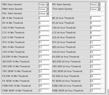
Step 5 Set the thresholds as follows:
| Displayed Information | Description |
|---|---|
DS1 Line | The slot and line number of the DS1 line |
Red Alarm Severity | Severity of near end Loss Of Frame. Values: major or minor. Default: major |
RMAI Alarm Severity | Severity of the RMAI alarm. Values: major or minor. Default: minor |
Perf. Alarm Severity | Severity of any performance alarms. Values: major or minor. Default: minor |
RAI Alarm Severity | Severity of Remote Alarm Indication. Values: major or minor. Default: minor |
TS16 Alarm Severity | Severity of the TS16 alarm. Values: major or minor. Default: minor |
Threshold counters (Table 6-2) | The thresholds for line errors that invoke a performance alarm. |
Refer to the following table for a list of threshold counters:
| Threshold | Description | Default1 |
|---|---|---|
LCV 15 | 15 minute line code violations | 14 |
LCV 24 | 24 hour line code violations | 134 |
LES 15 | 15 minute line errored seconds | 12 |
LES 24 | 24 hour line errored seconds | 121 |
UAS 15 | 15 minute unavailable seconds | 10 |
UAS 24 | 24 hour unavailable seconds | 10 |
FE ESR 15 | 15 minute errored second ratio caused by frame errors | 800 |
FE ESR 24 | 24 hour errored second ratio caused by frame errors | 800 |
FE SESR 15 | 15 minute severely errored second ratio caused by frame errors | 20 |
FE SESR 24 | 24 hour severely errored second ratio caused by frame errors | 20 |
FEBE ESR 15 | 15 minute far end block error resulting from ESR | 800 |
FEBE ESR 24 | 24 hour far end block error resulting from ESR | 800 |
FEBE SESR 15 | 15 minute far end block error resulting from SESR | 20 |
FEBE SESR 24 | 24 hour far end block error resulting from SESR | 20 |
CRC ESR 15 | 15 minute errored second ratio caused by CRC errors | 800 |
CRC ESR 24 | 24 hour errored second ratio caused by CRC errors | 800 |
CRC SESR 15 | 15 minute severly errored second ratio caused by CRC errors | 20 |
CRC SESR 24 | 24 hour severly errored second ratio caused by CRC errors | 20 |
ESR 15 | 15 minute errored second ratio caused by errored seconds | 800 |
ESR 24 | 24 hour errored second ratio caused by errored seconds | 800 |
SESR 15 | 15 minute severly errored second ratio caused by severly errored seconds | 20 |
SESR 24 | 24 hour severly errored second ratio caused by severly errored seconds | 20 |
ES 15 | 15 minute errored seconds | 35 |
ES 24 | 24 hour errored seconds | 50 |
SES 15 | 15 minute severely errored seconds | 35 |
SES 24 | 24 hour severely errored seconds | 50 |
BE 15 | 15 minute burst errors | 35 |
BE 24 | 24 hour burst errors | 50 |
PCV 15 | 15 minute path coding violations | 35 |
PCV 24 | 24 hour path coding violations | 50 |
CSS 15 | 15 minute controlled slip seconds | 35 |
CSS 24 | 24 hour controlled slip seconds | 50 |
| 1For ESR thresholds, the value shown equals 1000 time the actual ratio. |
Step 6 Click Modify.
The system applies the new thresholds.
To view E1 counters and performance alarms, follow these steps:
Step 1 On the Navigation pane, click Line.
Step 2 Click E1.
Step 3 Click All-Lines.
The E1 Line Configuration screen opens.
Step 4 On the E1 Line Configuration screen, click the C icon on the row with the desired line.
The E1 Line Alarm State and Statistics form opens, displaying the following three panes:

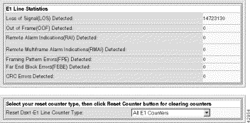
Alarm status is displayed as color-coded indicators with the following meaning:
Step 5 Interpret the alarm and counter panes as follows:
| Pane | Interpretation |
|---|---|
E1 Line Alarms | This group of indicators display E1 alarms and current test conditions. For more information on E1 alarms, see "Viewing E1 Alarms for Individual Lines" section. |
Line Performance Alarms | This group of indicators show performance alarms. For more information, see Table 6-2. |
Line Statistics | This group shows the number of times selected conditions occurred. |
To reset the counters, select the desired counter with Reset E1 Line counter Type and click the Reset Counter button on the bottom of the screen.
To view E1 real-time statistics, follow these steps:
Step 1 On the Navigation pane, click Line.
Step 2 Click E1.
Step 3 Click Counters and Alarm.
The E1 Line Counters/Alarm screen opens.
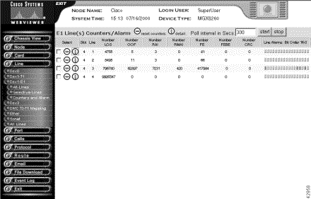
Step 4 Interpret the table as follows:
| Displayed Information | Description |
|---|---|
Slot | The slot hosting this line |
Line | The E1 line number for these statistics |
Number LOS | The number of times Loss of Signal was detected, with or without integrating to a LOS alarm |
Number OOF | The number of times Out of Frame was detected, with or without integrating to a OOF alarm |
Number RAI | The number of times RAI was detected, with or without integrating to a RAI alarm |
Number RMAI | The number of times RMAI was detected |
Number FE | The number of framing pattern errors detected |
Number FEBE | The number of far end block errors detected |
Number CRC | The number of CRC errors detected |
Line Alarms | The E1 line alarms, displayed as a row of indicators.
|
Line Performance Alarms | The E1 line performance alarms, displayed as a row of indicators.
|
To clear the counters, click the - icon on the row with the desired line. To view more alarm information, click the i icon on the row with the desired line. See the "Viewing E1 Performance Alarms" section. To filter the display, click the check box for rows you want to display. The display updates on the next poll.
To change the polling interval, follow these steps:
Step 1 Set the Poll Interval in Secs field.
Step 2 Click Start to restart the interval.
Step 3 Click Stop to stop polling.
Interval statistics are collected by each interface for the previous 24 hours of operation. The 24 hours are broken into 96 15-minute intervals. As time progresses, the system drops the oldest interval and adds the latest one, creating a sliding 24-hour window that moves with time.
To view interval E1 statistics, follow these steps:
Step 1 On the Navigation pane, click Line.
Step 2 Click E1.
Step 3 Click All-Lines.
The E1 Line Configuration screen opens.
Step 4 On the E1 Line Configuration screen, click the P icon on the row with the desired line.
The E1 Line Performance Statistics screen opens:

Step 5 Interpret the table as follows:
| Displayed Information | Description |
|---|---|
Interval | The 15 minute interval, where interval 1 is the most recent and 96 is the oldest. The Current interval is the interval currently accumulating statistics. The Total interval lists statistics for the past 24 hours |
<Statistic> | The statistics for each E1 performance metric. For a summary of statistic definitions, see "Setting E1 Alarm Thresholds" section |
To change the polling interval, follow these steps:
Step 1 Set the Poll Interval in Secs field.
Step 2 Click Start to restart the interval.
The MGX 8260 groups alarm and performance information as follows:
In addition to viewing alarm and performance information, you can set thresholds for performance alarms.
To view DS3 alarms, follow these steps:
Step 1 On the Navigation pane, click Line.
Step 2 Click Dsx3.
Step 3 Click All-Lines.
The Dsx3 Line Configuration form opens.
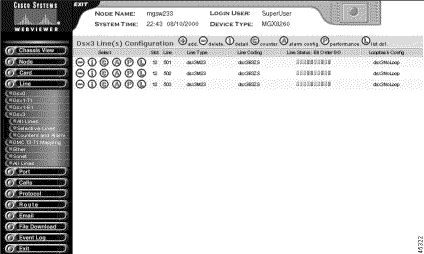
DS3 alarms are displayed as rows of indicators in the Line Status column.
Step 4 Interpret the color as follows:
Interpret the DS3 line status alarm display from right to left as follows:
You can open the Dsx3 Line Status and Configuration form for an individual line two ways:
To view line alarms for individual DS3 lines, follow these steps:
Step 1 On the Navigation pane, click Line.
Step 2 Click Dsx3.
Step 3 Click All-Lines.
The Dsx3 Line Configuration screen opens.
On the Dsx3 Line and Configuration screen, click the i icon on the row with the desired line. The Dsx3 Line Status and Configuration form opens with the following alarm pane:

Operational status is displayed as color-coded indicators.
Step 4 Interpret the color as follows:
Step 5 Interpret the alarms as follows:
| Alarm | Description |
|---|---|
No alarm present | Summary alarm indicator:
|
Receiving Remote Alarm Indication | Yellow alarm |
Transmitting Remote Alarm Indication | Yellow alarm |
Receiving AIS | Alarm indication signal |
Transmitting AIS | Transmitting alarm indication signal |
Receiving LOF | Loss of Frame detected |
Receiving LOS | Loss of signal detected |
Looping the received signal | Loopback is active |
Receiving a Test Pattern | Test signal detected |
Any other line status | Other DS3 failure |
This section describes how to change the configuration settings for alarm severity, integration period, and thresholds for various error conditions, such as LCV, LES, and LSES. The performance alarm is set if the DS3 errors exceed any of the threshold counts.
To change alarm threshold values, follow these steps:
Step 1 On the Navigation pane, click Line.
Step 2 Click Dsx3.
Step 3 Click All-Lines.
The Dsx3 Line and Configuration screen opens.
Step 4 On the Dsx3 Line and Configuration screen, click the A icon on the row with the desired line.
The Dsx3 Line Alarm Configuration form opens.
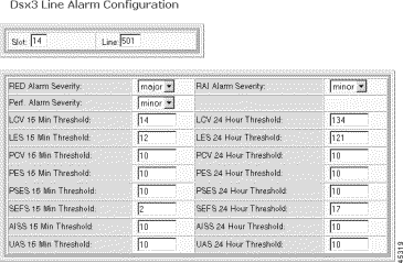
The current slot and line number are displayed at the top.
Step 5 Set the thresholds as follows:
| Displayed Information | Description |
|---|---|
Red Alarm Severity | The severity of near end LOF or LOS conditions:
|
RAI Alarm Severity
| The severity of remote alarm indication
|
Perf. Alarm Severity | The severity of any performance alarms. The performance alarm is raised if any of the threshold counters are exceeded.
|
Threshold counters | The thresholds for line errors that invoke a performance alarm. All counter thresholds are integers greater than zero. |
Step 6 Click Modify.
The system applies the new thresholds.
To view DS3 statistics and performance alarms, follow these steps:
Step 1 On the Navigation pane, click Line.
Step 2 Click Dsx3.
Step 3 Click All-Lines.
The Dsx3 Line Configuration screen opens.
Step 4 On the Dsx3 Line Configuration screen, click the C icon on the row with the desired line.
The Dsx3 Line Alarm State and Statistics form opens.

Alarm status is displayed as color-coded indicators. Interpret the color as follows:
Step 5 Interpret the alarm and counter panes as follows:
| Pane | |
|---|---|
Performance Alarms pane | This group of eighteen indicators show the performance alarm thresholds this line has exceeded |
Statistics pane | This group shows the number of times the error condition occurred |
To reset the counters, click Reset Counter.
To view DS3 real-time statistics, follow these steps:
Step 1 On the Navigation pane, click Line.
Step 2 Click Dsx3.
Step 3 Click Counters and Alarm.
The Dsx3 Line Counters/Perf screen opens.
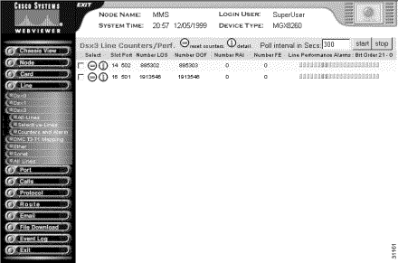
Step 4 Interpret the table as follows:
| Displayed Information | Description |
|---|---|
Slot | The slot hosting this line |
Port | The DS3 line number for these statistics |
Number LOS | The number of times per second Loss of Signal was detected, with or without integrating to a LOS alarm |
Number OOF | The number of times per second Out of Frame was detected, with or without integrating to a OOF alarm |
Number RAI | The number of times per second Yellow alarm was detected, with or without integrating to a RAI alarm |
Number FE | The number of framing pattern errors per second encountered by the DS3 interface |
Line Performance Alarms | The DS3 line performance alarms, displayed as a row of indicators:
|
To clear the counters, click the - icon on the row with the desired line.
To view more alarm information, click the i icon on the row with the desired line. See the "Viewing DS1 Performance Alarms" section.
To change the polling interval, follow these steps:
Step 1 Set the Poll Interval in Secs field.
Step 2 Click Start to restart the interval.
Step 3 Click Stop to stop polling.
Interval statistics are collected by each interface for the previous 24 hours of operation. The 24 hours are broken into 96 15-minute intervals. As time progresses, the system drops the oldest interval and adds the latest one, creating a sliding 24-hour window that moves with time.
To view interval DS3 statistics, follow these steps:
Step 1 On the Navigation pane, click Line.
Step 2 Click Dsx3.
Step 3 Click All-Lines.
The Dsx3 Line Configuration screen opens.
Step 4 On the Dsx3 Line Configuration screen, click the P icon on the row with the desired line.
The Dsx3 Line Performance Statistics screen opens.
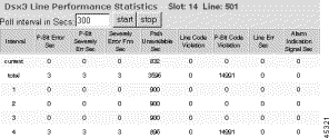
Step 5 Interpret the table as follows:
| Displayed Information | Description |
|---|---|
Interval | The 15 minute interval for the statistics. The Total interval lists statistics for the past 24 hours |
P Bit Err Sec | The number seconds with P Bit errors |
P Bit Sev Err Sec | The number seconds with severe P Bit errors |
Sev Err Frm Sec | The number of seconds with severe frame errors |
Unavailable Sec | The number of unavailable seconds |
Line Code Violations | The number of line code violations |
P Bit Code Violation | The number of seconds with P Bit violations |
Line Err Sec | The number of seconds with line errors |
C Bit Code Violation | The number of C Bit code violations |
C Bit Err Sec | The number of seconds with C Bit errors |
C Bit Sev Err Sec | The number of seconds with severe C Bit errors |
AIS Seconds | The number of seconds with AIS |
To change the polling interval, follow these steps:
Step 1 Set the polling interval field at the top of the form.
Step 2 Click Start to restart the interval.
Step 3 Click Stop to stop polling
To view Fast Ethernet alarms, follow these steps:
Step 1 On the Navigation pane, click Line.
Step 2 Click Ether.
Step 3 Click All-Lines.
The Ether Line Configuration form opens.
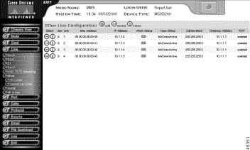
Step 4 Interpret the alarm status indicator as follows:
The MGX 8260 groups alarm and performance information as follows:
In addition to viewing alarm and performance information, you can set thresholds for performance alarms.
To view SONET alarms, follow these steps:
Step 1 On the Navigation pane, click Line.
Step 2 Click Sonet.
Step 3 Click All-Lines.
The Sonet Line Configuration form opens.

Step 4 Interpret the Line Status indicator as follows:
You can open the Sonet Line Status form for an individual line two ways:
To view line alarms for individual SONET lines, follow these steps:
Step 1 On the Navigation pane, click Line.
Step 2 Click Sonet.
Step 3 Click All-Lines.
The Sonet Line Configuration screen opens.
Step 4 On the Sonet Configuration screen, click the i icon on the row with the desired line.
The Sonet Line Status pane opens.
Line status is displayed as color-coded indicators.
Step 5 Interpret the color as follows:
To view SONET statistics and performance alarms, follow these steps:
Step 1 On the Navigation pane, click Line.
Step 2 Click Sonet.
Step 3 Click All-Lines.
The Sonet Line Configuration screen opens.
Step 4 On the Sonet Line Configuration screen, click the C icon on the row with the desired line.
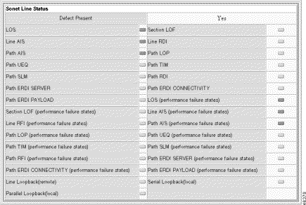
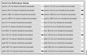
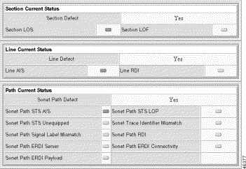
The Sonet Line Statistics screen opens, which includes the Sonet Line Alarms, Sonet Line Performance Alarms, Sonet Current Status, Line Current Status, and Path Current Status panes.

Alarm status is displayed as color-coded indicators. Interpret the color as follows:
Step 5 Interpret the alarm and counter panes as follows:
| Pane | Information Displayed |
|---|---|
Sonet Line Alarms | This group of indicators shows line alarms |
Sonet Line Performance Alarms | This group of indicators shows line performance alarms |
Section Current Status | This group of indicators shows section defects |
Line Current Status | This group of indicators shows line defects |
Path Current Status | This group of indicators shows path defects |
This section describes how to change the thresholds for SONET performance alarms. A performance alarm is set if the number of errors exceed the corresponding threshold.
To change alarm threshold values, follow these steps:
Step 1 On the Navigation pane, click Line.
Step 2 Click Sonet.
Step 3 Click All-Lines.
The Sonet Line and Configuration screen opens.
Step 4 On the Sonet Line and Configuration screen, click the A icon on the row with the desired line.
The Sonet Line Alarm Configuration form opens.

The current slot and line number are displayed at the top.
Step 5 Set the thresholds as follows:
| Displayed Information | Description |
|---|---|
Red Alarm Severity | The severity of near end LOF or LOS conditions:
|
RAI Alarm Severity
| The severity of remote alarm indication
|
Perf. Alarm Severity | The severity of any performance alarms. The performance alarm is raised if any of the threshold counters are exceeded.
|
Threshold counters | The thresholds for line errors that invoke a performance alarm. All counter thresholds are integers greater than zero (see Table 6-3). |
Step 6 Click Modify.
The system applies the new thresholds.
To view SONET real-time statistics, follow these steps:
Step 1 On the Navigation pane, click Line.
Step 2 Click Sonet.
Step 3 Click Section Performance, Line Performance, or Path Performance.
The system displays the real-time statistics.
Interval statistics are collected by each interface for the previous 24 hours of operation. The 24 hours are broken into 96 15-minute intervals. As time progresses, the system drops the oldest interval and adds the latest one, creating a sliding 24-hour window that moves with time.
To view interval SONET statistics, follow these steps:
Step 1 On the Navigation pane, click Line.
Step 2 Click Sonet.
Step 3 Click All-Lines.
The Sonet Configuration screen opens.
Step 4 On the Sonet Configuration screen, click the S, L, or P icon to view section, line, or path interval statistics for the desired line.
The corresponding screen opens. The line performance screen is shown below:
The MGX 8260 monitors three key environmental conditions:
Sensor readings translate to alarm conditions according to four fixed threshold levels.
To view shelf EMM alarms, follow these steps:
Step 1 On the upper right corner of any screen, click the Alarm icon. Alternatively, click Node and then click Alarm on the Navigation pane.
The Alarm Status screen opens.
Step 2 Click the i icon above the Shelf Alarm pane.
The Alarm Status screen for the shelf opens.
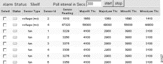
Step 3 Interpret the table as follows:
| Displayed Information | Description |
|---|---|
Status | The status of the environmental alarm:
|
SensorType | The type of environmental sensor |
SensorID | The number of a sensor on a unit |
Sensor Reading | The sensor reading:
|
Major Hi Threshold | The threshold value separating a major alarm from a minor alarm for high readings |
Major Lo Threshold | The threshold value separating a minor alarm for a high reading from normal operation |
Minor Hi Threshold | The threshold value separating a major alarm from a minor alarm for a low reading |
Minor Lo Threshold | The threshold value separating a minor alarm for a low reading from normal operation |
To filter the display, click the check box on the desired rows. The display updates on the next poll.
To change the polling interval, follow these steps:
Step 1 Set the Poll Interval in Secs field.
Step 2 Click Start to restart the interval.
Step 3 Click Stop to stop polling.
To view card EMM alarms, follow these steps:
Step 1 On the upper right corner of any screen, click the Alarm icon. Alternatively, click Node and then click Alarm on the Navigation pane.
The Alarm Status screen opens.
Step 2 Click the i icon above the Logical Card Alarm pane.
The Alarm Status for cards screen opens.
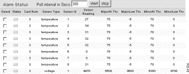
Step 3 Interpret the table as follows:
| Displayed Information | Description |
|---|---|
Status | The status of the environmental alarm:
|
Card Num | The number of the card for the EMM status |
SensorType | The type of environmental sensor |
SensorID | The number of a sensor on a unit |
Sensor Reading | The sensor reading:
|
Major Hi Threshold | The threshold value separating a major alarm from a minor alarm for high readings |
Major Lo Threshold | The threshold value separating a minor alarm for a high reading from normal operation |
Minor Hi Threshold | The threshold value separating a major alarm from a minor alarm for a low reading |
Minor Lo Threshold | The threshold value separating a minor alarm for a low reading from normal operation |
To filter the display, click the check box on the desired rows. The display updates on the next poll.
To change the polling interval, follow these steps:
Step 1 Set the Poll Interval in Secs field.
Step 2 Click Start to restart the interval.
Step 3 Click Stop to stop polling.
To view the event log, follow these steps:
Step 1 On the Navigation pane, click Log.
Step 2 Click the Trap Log submenu item.
The trap criteria form opens.
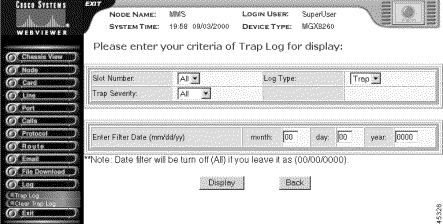
Step 3 Enter one of the following types of events to display:
| Event | Description |
|---|---|
Slot Number | The slot number, 1-16 or all |
Event Severity | The event severity:
|
Event Type | The type of event: Trap only |
Step 4 Click Display.
After a delay, the trap log opens:
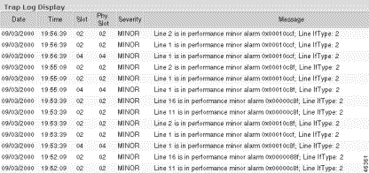
Step 5 Interpret the event log as follows:
| Displayed Information | Description |
|---|---|
Date | The event date |
Time | The event time |
Slot | The slot number generating the event |
Severity | The event severity |
Type | The event type |
Message | The event description |
To clear the event log, follow these steps:
Step 1 On the Navigation pane, click Log.
Step 2 Click Clear Trap Log.
A confirmation screen opens.
Step 3 Confirm your action by clicking Clear Trap Log.
![]()
![]()
![]()
![]()
![]()
![]()
![]()
![]()
Posted: Mon Nov 25 11:03:59 PST 2002
Copyright 1989-2000©Cisco Systems Inc.