|
|

This chapter explains how to configure cards and lines for service delivery.
Card parameters control the operational characteristics of the card as a whole. The MGX 8260 Media Gateway supports the following cards:
The SCC provides overall system control and database management for the shelf. In addition, the card provides optional broadband interfaces to the WAN backbone network, such as Fast Ethernet or SONET. SCCs are always in slots 9 or 10. When SCCs are installed in both slots, they operate as a redundant pair.
The NSC adapts different media types and switches signals between carrier networks and services. The NSC supports a range of service and applications for both voice and data calls. NSCs are always in slots 1-8 and 11-16.
The BSC adapts different media types and switches signals between carrier networks and services. The BSC supports a range of service and applications for both voice and data calls, including DS3 circuits. BSCs are always in slots 11-16.
The MGX 8260 Media Gateway supports full multiplexing/demultiplexing and TDM-based switching at DS3 rates through the DMC. The DMC receives DS3 signals and distributes the services across NSC modules for processing. DMCs are always in slots 7 or 8.
See the following sections for card configuration tasks.
This sections describes how to view and set card-level parameters.
To list information for a single card, enter the lscd command, specifying the card location by a slot number in the MGX 8260 chassis. Slots are numbered from 1 through 16, starting at the left.
The system displays the card information.
|
To list summary information for all cards, enter the lscds command.
The system displays information for all cards:
To view DSP information, enter the lsdsps command.
The system lists current DSP information:
To view MSM information, enter the lsmsms command.
The system lists current MSM information:
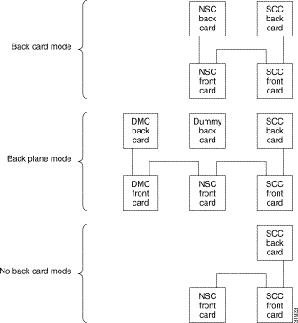
The interface mode controls the signal source for the T1 interface of an NSC card. There are three modes (see Figure 3-1)
All sixteen T1 lines operate in the same mode. The system ignores this setting for cards other than the NSC.
In the back card mode, the NSC transmits and receives traffic through the back card and its T1/E1 interface. The normal signal flow in this case is:
Choose the back card mode when you are using the NSC card with a T1/E1 back card.
In the back plane mode, VoIP transmits and receives traffic from the DMC front card. The normal signal flow when using a DMC card is:
Use the back plane mode when you use the NSC card in conjunction with a DMC card and DS3 lines.
In the no back card mode, the NSC transmits and receives traffic from a SCC front card. The normal signal flow in this case is:
Use the no back card mode when using the NSC in conjunction with the SCC Fast Ethernet.
You can only change the interface mode on an NSC while it's in one of the following states:
To set the NSC interface mode, enter the chcdif command, specifying the card number and NSC interface mode. Valid NSC interface mode settings are:
 |
Note Configuring the back card mode with out a back card installed results in a card mismatch. |
The system sets the specified interface mode on the target NSC card. The following example sets the interface mode of card 13 to back plane:
The card resets and reboots into backplane mode.
The ATM queue profile defines the queue behavior for the SCC card. You can only change the ATM Queue profile on the active SCC.
To set the ATM queue profile, enter the chqprf command, specifying the slot number of the SCC card, either 9 or 10, and the queue profile, a number from 1 to 10. Profile 1 is the default.
The system sets the specified queue profile on the target SCC card.
The resetcd command restarts a card and restores its stored configuration. The following table shows response of the reset command for different card types and operating states:
Table 3-1 Response of Reset Command by Card and State
|
 |
Warning Resetting a card interrupts service. Perform this operation during light traffic periods or in a pre-arranged maintenance window. |
To reset a card, enter the resetcd command, specifying the card to reset.
The following example resets card 13:
The MGX 8260 Media Gateway supports both redundant and non-redundant operation for all cards. The SCC and DMC don't require user setup for redundant operation. To configure redundancy for the NSC or BSC, you define protection pairs. The Cisco MGX 8260 uses 1:N protection for NSCs and 1:1 protection for BSCs. With protection, the system switches to a protection card if an active card fails.
Cards configured for redundancy may have logical numbers that are different than physical slot numbers. The physical slot number always represents the physical location of the card in the chassis. The logical slot number is an abstract concept that helps the system keep track of primary and secondary cards.
With 1:1 redundancy, the primary and secondary cards both have the same logical slot number. As such, the system treats them as a single entity for configuration operations. With 1:N redundancy, the secondary card uses logical slot number 0. During switchover, the secondary card assumes the logical number of the card it protects.
A single secondary card can support multiple primary cards. In this configuration, a failure of any of the primary cards causes a switchover to the designated secondary. After a switchover, the other NSCs are unprotected until you fix the problem and restore the primary card to the active state.
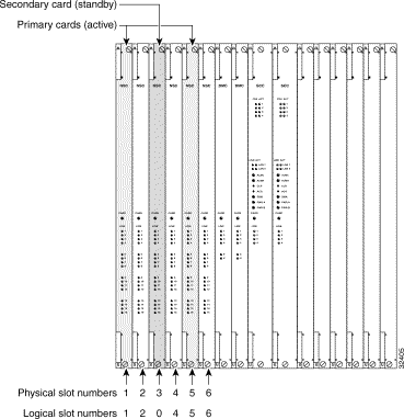
For example, a 1:2 redundancy configuration with slot 3 covering slot 1 and slot 5 actually has two redundancy pairs (see Figure 3-2).
Slot 1 is paired with slot 3, with slot 1 as the primary. Slot 5 is also paired with slot 3 with slot 5 as the primary. You can continue to add redundancy pairs to build other ratios of protection. However, you can only have one secondary slot per MGX 8260 chassis. That single secondary slot protects all primary NSC cards in the chassis.
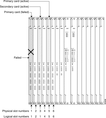
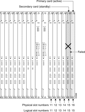
If the primary card in slot one fails, the system switches to the secondary NSC, and the secondary NSC assumes the logical slot number of the card that failed (see Figure 3-3).
The logical slot number of the secondary card changes to 1, even though its physical slot number is 3. Had the slot 5 failed rather than slot 1, the logical slot number of the secondary card would have changed to 5.
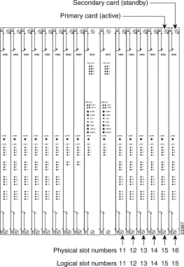
You configure BSC protection using a pair of cards configured for 1:1 redundancy. After you configure a redundant pair of BSCs, both cards reboot and return to operation with the same logical slot number. The card LED displays green for the active card and yellow for the standby card.
For example, you can configure cards 15 and 16 for redundancy (see Figure 3-4).
A failure of the active card causes a switchover to the backup card. During the switchover, the active and standby roles are reversed (see Figure 3-5). The card that failed reboots, and the Card LED changes to either yellow or red, depending on the type of problem. After a switchover, the other BSC is unprotected until you fix the problem and restore the primary card to the active state.
After repair of the failure, you restore normal operation by invoking a switchback. The system does not automatically restore the protection pair to its original state. For more information, see Invoking a Switchback.
This section describes the process for configuring redundancy for BSC and NSC cards.
To view all redundancy pairs, enter the lsreds command.
The system displays all redundancy pairs:
|
There are two possible NSC redundancy scenarios: with and without DMC.
This scenario requires a redundant back card in the secondary slot. The back card protects the primary slots in the event of a primary card failure.
This scenario does not require, and cannot have, a redundant back card.
Both scenarios require assignment of primary and secondary slot numbers in pairs. The MGX 8260 chassis only supports one secondary slot.
To configure NSC redundancy without DMC, follow these steps:
Step 2 Verify that each primary, active NSC is in the back card mode and is in the active state. List the operational status of all cards using the lscds command.
Step 3 Add a redundancy pair using the addreds command, specifying the slots of the primary and secondary slots.
The primary slot is active during normal operation. The secondary slot is in standby during normal operation and protects the primary slot in the event of a primary failure.
The following example creates a redundancy pair with slot 1 as primary and slot 3 as secondary:
Step 4 Repeat the previous step to assign additional primary slots to the designated secondary slot. Each MGX 8260 chassis can have only one secondary slot.
To configure NSC redundancy with DMC, follow these steps:
Step 2 Verify that the redundant NSC does not have a redundancy back card installed. See "Viewing Summary Information for Cards" section.
Step 3 Verify that each primary NSC does not have a back card installed.
Step 4 Add a redundancy pair using the addreds command.
Step 5 Repeat the previous step to assign additional primary slots to the designated secondary slot. Each MGX 8260 chassis can have only one secondary slot for NSC cards.
In order to successfully configure a redundant pair, the following conditions must be true:
|
Warning Adding BSC redundancy interrupts service. Perform this operation during light traffic periods or in a pre-arranged maintenance window. |
To configure BSC redundancy, follow these steps:
Step 2 Add a redundant "Y" cable between all ports on the two cards.
Step 3 From a management session, add a redundancy pair using the addreds command.
Both cards reboot and return to operation with the same logical slot number.
To delete a redundancy pair, enter the delreds command specifying the primary and secondary slots. The following example deletes the redundancy pair where slot 1 is primary and slot 3 is secondary:
The redundant card continues to protect other primary cards with which it is paired.
The switchover from primary to secondary cards is automatic when a primary card fails. Switching back is a manual task. The following table shows the response of the switchback command as a function of card type and operational state:
Table 3-2 Response for the Switch Card Command by Card and State
|
To force a switchback, enter the swcd command specifying the physical number of the primary card in a protection pair.
|
Note To force a switchover, rather than a switch back, reset the primary card using resetcd. |
You can save or restore system configuration from a tftp server on the management network. To use tftp, you must conform to the Cisco file-naming convention and supply a six-character security key. The security system disables tftp file transfers if the key is missing or does not match. The following procedures explain how to save and restore card configurations.
You can back up the current MGX 8260 configuration with the dbbkup command. This command captures the configuration information for all cards and saves it to a file on the SCC hard drive. The system assigns a name for this file and reports it to the user.
To save a card configuration, follow these steps:
Step 2 At the command prompt, type dbbkup.
The system reports the result of the operation and the name of the backup file.
Step 3 Record the file name for future reference. By default, the backup file name matches the software version name with a .cfg extension. For example, the backup file for software release R01.02.03 is SCC_R01.02.03.CFG
The MGX 8260 stores configuration information for all cards in the chassis in the SCC hard drive. You can upload this configuration information to an external server for safekeeping. Before performing this procedure, check your records to determine the name of the backup file you want to upload.
To upload a configuration file, follow these steps:
Step 2 Initiate a tftp session with the target MGX 8260 Media Gateway using the tftp command.
Specify the IP address of the MGX 8260 management port in standard IP dot notation.
|
Note tftp is an operating system command executed by the management workstation. |
Step 3 Set the transfer mode to binary:
Step 4 Start the file transfer using the tftp get command.
|
Step 5 Confirm the file transfer by checking the distribution directory.
The MGX 8260 stores configuration files on the SCC hard drive, so you generally don't need to download a configuration file. However, if you prefer to save configuration files on an external server, you can download the file to the MGX 8260 before invoking dbrstr. Before performing this procedure, check your records to determine the name of the backup file you want to download.
To restore a card configuration, follow these steps:
Step 2 Initiate a tftp session with the target MGX 8260 Media Gateway using the tftp command.
Specify the IP address of the MGX 8260 management port in standard IP dot notation.
|
Note tftp is an operating system command executed by the management workstation. |
Step 3 Set the transfer mode to binary using the tftp mode command.
Step 4 Start the file transfer using the tftp put command.
|
Step 5 Confirm the file transfer.
You can restore the MGX 8260 to a previous configuration using the dbrstr command. This command retrieves a configuration file from the SCC hard disk and restores all cards accordingly. Before performing this procedure, check your records to determine the name of the backup file you want to restore.
|
Warning This is a service-affecting action. Perform this task when the equipment is down or during a pre-arranged maintenance window. |
To restore MGX 8260 configurations, follow these steps.
Step 2 At the command prompt, type database restore command and the configuration file name. Omit the .cfg extension from the file name.
Step 3 Restart the target card using the resetcd command.
This section describes the software upgrade paths, security key requirements, installation procedures, and database configurations needed for software upgrade.
Release 1.2.5 software supports graceful upgrades from the following releases:
A security key is required for the transfer of files to the MGX 8260 through use of the UNIX tftp function. To determine the appropriate MGX 8260 security key code, use the lskey command from the command line interface.
The following sections describe the process you use to download MGX 8260 software from the Cisco web or ftp sites, transfer the files to the MGX 8260, and download the files to each card.
To download MGX 8260 software images, refer to the Cisco software center on Cisco Connection Online (CCO), located at the following URL:
For instructions on how to download software, refer to the link for "Using the Software Center".
MGX 8260 software includes the following files:
To upgrade the MGX 8260, download the new system software from CCO to a management server on your network that supports the UNIX tftp function.
Using tftp, transfer the files to the MGX 8260 using the following procedure:
Step 2 Initiate a tftp session with the target MGX 8260 Media Gateway using the tftp command.
Specify the IP address of the MGX 8260 management port in standard IP dot notation.
Step 3 Set the transfer mode to binary with the following command:
Step 4 Use the following tftp commands to transfer SCC software to the MGX 8260:
tftp> put vxWorks_dnld.scc.fw scc_r01.02.05.img.[key]
tftp> put vxWorks_boot.scc.fw scc_r01.02.05.fls.[key]
For information about the security key [key], refer to the "Security Key Requirements" section.
Step 5 Use the following tftp commands to transfer BSC software to the MGX 8260:
tftp> put vxWorks_dnld.bsc.fw bsc_r01.02.05.img.[key]
tftp> put vxWorks_boot.bsc.fw bsc_r01.02.05.fls.[key]
Step 6 Use the following tftp commands to transfer NSC software to the MGX 8260:
tftp> put vxWorks_dnld.nsc.fw nsc_r01.02.05.img.[key]
tftp> put vxWorks_boot.nsc.fw nsc_r01.02.05.fls.[key]
Step 7 Close your tftp session.
Before performing an upgrade, make sure you have a current backup of the configuration database. Back up the database using the dbbkup command from the command line interface.
 |
Caution All modules must be upgraded to the new release of software during the upgrade process. Performing a partial upgrade (For example, some, but not all BSCs, or some, but not all NSCs) could cause unexpected behavior in MGX 8260 system operation. |
|
Note The installation procedure described here is for a graceful upgrade process from the software release indicated in the "System Software Upgrade Paths" section to the current release. |
The general process to upgrade software on all cards is as follows:
1. Initiate a Telnet session with the target MGX 8260 Media Gateway, specifying the IP address of the MGX 8260 management port in standard IP dot notation.
2. Log in as superuser or a user with level 1 privileges.
3. Follow the upgrade procedures for each card type.
4. Log out of your Telnet session.
|
Note We recommend that you use the upgrade procedures while simultaneous console connections are established to both the active and the standby SCC. |
The upgrade process for redundant SCCs is graceful. It does not interrupt established calls, but it can interrupt calls in the process of being established. When you invoke the upgrade process, the MGX 8260 upgrades and restarts the standby SCC. You can then commit or cancel the upgrade. When you commit the software, the MGX 8260 switches to the standby SCC and then upgrades the other SCC.
|
Warning Upgrading nonredundant cards interrupts service. Perform nonredundant upgrades during light traffic periods or during a prearranged maintenance window. |
To upgrade SCC and software images, perform the following steps:
updatefls <physicalSlotNumber> IMAGE/SCC/scc_r01.02.05.fls
Step 2 Ensure that the standby SCC is in the standby state.
Step 3 Upgrade the software image on the active SCC using the following command:
|
Note Enter a 9 even if card 10 is active. This parameter refers to logical card 9. The active SCC is always logical card 9 regardless of its physical slot location. |
In redundant configurations, the upgd command resets the standby SCC. Wait until the standby SCC reboots and its console session shows a standby state. At that point, the standby SCC will be running the new release of boot Flash and software images.
Step 4 You can now commit or cancel the upgrade.
a. For redundant SCCs, if you wish to cancel the upgrade, enter the upgdcancel command. Use this command only if you have not entered the upgdcmit command. You cannot cancel an upgrade for nonredundant cards.
|
Note Before you cancel an upgrade with the upgdcancel command, you need to to reset the previous software on the flash card using the updatefls command. |
On redundant systems, the upgdcmit command switches over the two SCCs. The SCC that was standby is placed into active state with its newly upgraded database and software image, and the previously active SCC resets and boots up to standby state.
|
Warning You must execute either the upgdcmit command in Step 4b. or the upgdcancel command in Step 4a. If you do not execute one of these commands, database corruption will occur. |
Step 5 Ensure that the previously active SCC has completed booting and is in standby state.
Step 6 On redundant systems, force a switchback to the primary card using the swcd command:
The upgrade process for redundant BSCs is graceful. It does not interrupt established calls, but it can interrupt calls in the process of being established. When you invoke the upgrade process, the MGX 8260 upgrades and restarts the standby BSC. You can then commit or cancel the upgrade. When you commit the upgrade, the MGX 8260 switches to the standby BSC and then upgrades the other BSC.
|
Warning Upgrading nonredundant cards interrupts service. Perform nonredundant upgrades during light traffic periods or during a prearranged maintenance window. |
If your MGX 8260 includes BSCs, perform the following steps to upgrade BSC Flash and software images:
updatefls <physicalSlotNumber> IMAGE/BSC/bsc_r01.02.05.fls
Step 2 Ensure that the standby BSC is in the standby state.
Step 3 Upgrade the BSC software image using the following command. Issue the command for the first primary BSC in your system, replacing the <logicalSlotNumber> with the appropriate number for your configuration.
upgd <logicalSlotNumber> bsc_r01.02.05.fw
Answer Y to the "Are you sure?" warning message.
In redundant configurations, the upgd command resets the secondary BSC matched with the primary BSC you specified in <logicalSlotNumber>. The secondary is now running the new release of boot Flash and the software images.
Step 4 Ensure that the standby BSC has finished booting and is in the standby state.
Step 5 You can now commit or cancel the upgrade.
a. For redundant BSCs, if you wish to cancel the upgrade, enter the upgdcancel command. This command can be used only if you have not entered the upgdcmit command. You cannot cancel an upgrade for nonredundant cards.
|
Note Before you cancel an upgrade with the upgdcancel command, you need to to reset the previous software on the flash card using the updatefls command. |
b. To commit the new software, use the following command. Issue the command for the first primary BSC in your system, replacing the <logicalSlotNumber> with the appropriate number for your configuration.
If you have redundant BSCs installed, the upgdcmit command switches over the two BSCs. The BSC that was secondary (with its newly upgraded database and software image) becomes the primary BSC, and the previously primary BSC becomes the secondary BSC.
|
Warning You must execute either the upgdcmit command in Step 5b. or the upgdcancel command in Step 5a. If you do not execute one of these commands, database corruption occurs. |
Step 6 Ensure that the previously primary BSC has finished booting and is in the standby state.
Step 7 On redundant systems, force a switchback to the original primary BSC using the swcd command:
Where <standbySlotNumber> is the number of the original secondary BSC (the BSC that is currently in active state).
Step 8 Repeat Step 2 through Step 7 for additional BSC pairs in your system.
The upgrade process for redundant NSCs is graceful. It does not interrupt established calls, but it can interrupt calls in the process of being established. When you invoke the process, the MGX 8260 upgrades and restarts the standby NSC. You can then commit or cancel the upgrade. When you commit the upgrade, the MGX 8260 switches to the standby NSC and then upgrades the other NSC.
|
Warning Upgrading nonredundant cards interrupts service. Perform nonredundant upgrades during light traffic periods or during a prearranged maintenance window. |
NSC redundancy follows an N:1 design, with one NSC providing redundancy for all remaining NSCs.
If your MGX 8260 includes NSCs, perform the following steps to upgrade NSC Flash and software images:
updatefls <physicalSlotNumber> IMAGE/NSC/nsc_r01.02.05.fls
Step 2 If your system includes NSC redundancy, identify the slot number of the NSC providing redundancy.
Step 3 Enter the following command for the first NSC in your system (excluding the redundant NSC identified in Step 2). Replace the <logicalSlotNumber> with the appropriate number for your configuration.
upgd <logicalSlotNumber> nsc_r01.02.05.fw
Answer Y to the "Are you sure?" warning message.
In redundant configurations, the upgd command resets the redundant NSC. The redundant NSC should now be running the new release of boot Flash and software images.
Step 4 Ensure that the standby/redundant NSC has finished rebooting and is in the standby state.
Step 5 You can now commit or cancel the upgrade.
a. If your MGX 8260 is configured for NSC redundancy, and you wish to cancel the upgrade, enter the upgdcancel command. You can use this command only if you have not entered the upgdcmit command. You cannot cancel an upgrade for nonredundant cards.
|
Note Before you cancel an upgrade with the upgdcancel command, you need to to reset the previous software on the flash card using the updatefls command. |
b. To commit the new software, use the following command. Issue the command for the first NSC as indicated in Step 3. Replace the <logicalSlotNumber> with the appropriate number for your configuration.
|
Warning You must execute either the upgdcmit command in Step 5b. or the upgdcancel command in Step 5a. If you do not execute one of these commands, database corruption occurs. |
Step 6 Ensure that the previously standby NSC is now active and that the NSC in <logicalSlotNumber> is now in standby state.
Step 7 For an MGX 8260 configured for NSC redundancy, force a switchback to the NSC indicated in Step 3. Use the swcd command:
Where <standbySlotNumber> is the number of the standby/redundant NSC (currently in active state).
Step 8 Repeat Step 3 through Step 7 for all NSCs in your system.
|
Note If the NSC does not have a back card, it may reboot in MISMATCH state. Fix this by entering the command chcdif <logicalSlotNumber> 3. This returns the NSC to No-Back-Card mode. |
You do not need to clear the configuration database when performing a graceful upgrade from Release 1.2.2, 1.2.3, or 1.2.4 to Release 1.2.5. Nongraceful upgrades require a database reconfiguration.
![]()
![]()
![]()
![]()
![]()
![]()
![]()
![]()
Posted: Wed Nov 5 22:00:25 PST 2003
All contents are Copyright © 1992--2003 Cisco Systems, Inc. All rights reserved.
Important Notices and Privacy Statement.