|
|

System management commands configure the parameters of an MGX 8260 node that define overall operation and interactions with other nodes and servers.
Before you can configure the MGX 8260 Media Gateway, you must log on as a user with the privilege to change system parameters. You need SuperUser privileges to change most system-level settings. To log on, follow these steps:
Step 1 Open a telnet session with the MGX 8260 Media Gateway. You need to know the host name or IP address for the desired MGX 8260 node.
Step 2 At the User Id prompt, enter your user name. On a new system, use SuperUser.
Step 3 At the Password prompt, enter your password. On a new system, use cisco.
The MGX 8260 Media Gateway displays a command line prompt.
See the following sections for configuration tasks related to managing the system:
You use the command line interface to enter system management commands.
The MGX 8260 controls user access two ways:
The MGX 8260 Media Gateway enforces security with user accounts and access levels. Users must log onto the MGX 8260 Media Gateway before performing any task, and authenticated users can perform only those tasks permitted by their access level. The MGX 8260 Media Gateway supports up to 20 user accounts, each with access privileges ranging from full control to guest (see Table 2-1).
| Access Level | Account type | Command groups |
|---|---|---|
1 | SuperUser | Access all features |
2 | Administrator | Configure and view all features except user profiles and community strings |
3 | Provisioning | Configure and view system, port, lines, end points, and connections |
4 | Maintenance | Access selected level 3 commands |
5 | Operator | View system, port, lines, end points, and connections |
6 | Guest | View system, common lines and ports |
A new system has a default SuperUser account. To prohibit unauthorized access to the equipment, replace the default account with a unique one.
 |
Note The Command Line Reference lists the specific access level for each command. |
To list existing user profiles, follow these steps:
Step 1 Log on to the MGX 8260 Media Gateway at access level 1.
Step 2 Enter the lsusps command.
The system lists the users.
=============================================================
              User Profile Entries (lsusps)
=============================================================
Index  User Identifier   Access Level
=====  ===============   ============
  1         William              1
  2         user3                3
Only users with access level 1 can add new profiles to the MGX 8260 Media Gateway.
To add a new user profile, follow these steps:
Step 1 Log on to the MGX 8260 Media Gateway at access level 1.
Step 2 Enter the addusp command, specifying the user ID and access level:
The system adds a new user with a default password that matches the user id.
The following example adds a user named William with a default password of William and an access level of 1:
addusp William 1
Change the default password to a unique password as described in the next section.
Every user can change their own password. If the existing password is unknown, a level 1 user must delete the account and add a new one.
To change a password, follow these steps:
Step 1 Log onto the account you want to change.
Enter the chpwd command and respond to the following prompts that appear:
Rules:
1. Password length must be 4 - 10
2. First character must be alphanumeric
3. Only printable characters are allowed
4. Space not allowed
Enter Password : *****
New Password   : ********
Verify Password: ********
The system updates the account password.
To delete a user profile, follow these steps:
Step 1 Log on to the MGX 8260 Media Gateway at access level 1.
Step 2 Enter the delusp command, specifying the ID of the user whose profile you want to delete:
The system removes the user profile from the database.
For example, the following command removes the user profile for William:
delusp William
You can view summary or detail information for current logins.
To view summary information about all active logins, use the lslogins command. The system displays the following summary information:
================================================================================
                     User Login Session Entries (lslogins)
================================================================================
Index      User ID      AcLevel  LoginTIME  LoginDATE      IP Address    SesType
=====  ===============  =======  =========  ==========  ===============  =======
  1          SuperUser      1     12:08:02  08/15/2000   172.16.252.107   telnet
| Displayed Information | Description |
|---|---|
Index | The index number of the user account |
User ID | The name of the user |
AcLevel | The access level of the user |
LoginTIME | The time the user logged in |
LoginDATE | The date the user logged in |
IP Address | The IP address of the user's host |
SessType | The type of login session the user is using, either telnet, console, or web |
To view detail information about one active logins, use the lslogin command. The system displays the following summary information:
============================================================
                 User Session Entry (lslogin)
============================================================
User Session Index        :   1
User Identifier           :   SuperUser
User Access Level         :   1
User Login Time           :   12:08:02
User Login Date           :   08/15/2000
User Ligin IP Address     :   172.16.252.107
User Login Session Type   :   telnet
For a description of the listing, see the previous procedure for lslogins.
When managing the MGX 8260 Media Gateway from a SNMP manager, security is enforced with password-like community strings. SNMP communities are groupings of workstations and servers (or gateways) that can manage the MGX 8260. Community strings are important when managing the MGX 8260 Media Gateway from a Network Management System, like HP Openview. You can configure up to 15 community strings.
To view a particular community string, enter the lscms command, specifying the community string index.
The system displays the community string information:
=======================================================================
              Community String Entry (lscms)
=======================================================================
        Community String Index :1
        Commumity String       :Public
        Manager IP Address     :0.0.0.0
        Privilege              :read-write
| Displayed Information | Description |
|---|---|
Community String Index | The commStrTable index number, from 1 to 15. If you don't know the index, list all community strings first and identify the string of interest. The following procedure shows how to list all community strings. |
Community String | The name of the community string. |
Manager IP Address | The IP address of the manager associated with this string. |
Privilege | The manager's privilege, either read-write or read-only. |
To view all community strings, enter the lscmss command.
A list of all SNMP community strings is displayed, along with the corresponding index values, manager IP addresses, and privileges.
=============================================================
              Community String Entries (lscmss)
=============================================================
Index   Manager IP Address   Privilege    Community String
=====  ==================== ===========  ===================
  1          10.1.1.2         read-only       public
  2          10.1.1.3         read-write      private
For a description of the output, refer to the description of the lscms command in the previous section.
To add a community string, enter the addcms command, specifying the community, such as "public", the IP address of the SNMP manager, and the privilege (read-only = 1 or read-write = 2). An IP address of 0.0.0.0 specifies all SNMP managers. Community strings contain up to 20 characters.
The following command adds a public community string with read-write privilege for all SNMP managers:
addcms Public 10.0.0.0 2
To delete a community string, enter the delcms command, specifying the community string and IP address.
For example, the following command deletes the Public community string:
delcms Public 0.0.0.0
The tftp key authenticates file transfers between the MGX 8260 Media Gateway and a tftp client. If the key is not set, or if the key provided during the file transfer does not match this key, the file is not transferred.
To set the security key, enter the chkey command, specifying the security key. The system records the security key.
To view the security key, enter the lskey command. The system displays the security key.
System-wide parameters apply to the MGX 8260 node as a whole. System-wide parameters include the following settings:
To view system-wide parameters, enter the lsndinf command.
The system displays the node and backplane information:
=======================================================================
          Node Information (lsndinf)
=======================================================================
System Rack Number       :    1
System Node Name         :    MMS
System Node Type         :    mgx8260
System BackPlane Type    :    1
System BackPlane Serial #:    BKPLN
System DS1 Type          :    t1
System Node Number       :    1
Gateway Control Protocol :    mgcp
| Displayed Information | Description |
|---|---|
System Rack Number | The physical location of the shelf. |
System Node Name | The user-defined name for this node |
System Node Type | The node type—MGX 8260 |
System BackPlaneType | The Cisco backplane type |
System BackPlane Serial # | The backplane serial number |
System DS1 Type | The line type setting, either T1 or E1 |
System Node Number | The user-defined number for this node |
Gateway Control Protocol | The call control protocol setting, either MGCP or IPDC |
To view the date and time, enter the lsdate command.
The system displays the date, time, and time zone:
=======================================================================
          System Time and Date Information (lsdate)
=======================================================================
Date                   :      03/21/1999
Time                   :      22:14:12
TimeZone               :      gmtplus12
Normally, system-wide parameters are set during installation.
To change node parameters, follow these steps:
Step 1 Configure the system rack number, node name, node number, and DS1 type using the chndinf command.
Step 2 Set the system date, time, or timezone, using the chdate and chtimezn commands.
Use this command to configure the chassis for T1 or E1 lines - you can't mix T1 and E1 lines on a single chassis. Before switching from T1 to E1, verify the following conditions:
When switching from E1 to T1, make sure there are no E1 lines configured.
To change the line type to DS1 or E1, use the chsyslnmd command. The chassis automatically resets and restarts with the selected line type.
 |
Warning Changing DS1 line type interrupts service. Perform this operation during light traffic periods or in a pre-arranged maintenance window. |
To change the protocol to MGCP or IPDC, use the chprotocol command. The chassis automatically resets and restarts with the selected protocol.
|
Warning Changing the gateway protocol interrupts service. Perform this operation during light traffic periods or in a pre-arranged maintenance window. |
You configure the MGX 8260 management interface for local or remote operation by setting the appropriate IP addresses and management paths. Assign management IP addresses for each of the following management interfaces that you plan to use:
You view all management parameters with a single command. The following management port parameters are displayed:
To view management port parameters, enter the lsmgips command.
The management interface configuration is displayed:
=========================================================================
           Management Interfaces Configuration (lsmgips)
=========================================================================
SNMP Interface IP1 Address   :          10.15.26.20
SNMP Interface IP1 Mask      :          255.255.255.0
SNMP Interface IP2 Address   :          10.15.27.20
SNMP Interface IP2 Mask      :          255.255.255.0
SNMP Interface MAC Address   :          00:50:a3:00:26:c8
In-Band Interface Address    :          10.15.28.20
In-Band Interface Mask       :          255.255.255.0
| Displayed Information | Description |
|---|---|
SNMP Interface IP1 Address | The IP address of the primary 10BaseT management interface |
SNMP Interface IP1 Mask | The IP subnet mask for the primary interface |
SNMP Interface IP2 Address | The IP address for the secondary 10BaseT management interface |
SNMP Interface IP2 Mask | The IP subnet mask for the secondary interface |
SNMP Interface MAC Address | The physical MAC address for the MGX 8260 Media Gateway |
Inband Interface Address | The IP address of the in-band management interface |
Inband Interface Mask | The IP subnet mask for the in-band management interface |
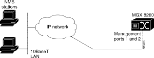
You use the SCC 10BaseT management port for http, telnet, SNMP, and TFTP sessions. Management hosts are physically connected to the 10BaseT port of the MGX 8260 Media Gateway (see Figure 2-1).
 |
Tip Change management IP address from the console port rather than a telnet session. |
To configure the 10BaseT management port, follow these steps:
Step 1 Connect a VT100 terminal to the console port.
Step 2 Log onto the MGX 8260 Media Gateway as a SuperUser.
Step 3 Set the IP address and mask for the primary management interface using the chsysip1 command.
For example, with a system IP address of 10.15.26.20 and a 24-bit subnet mask, enter the following command:
chsysip1 10.15.26.20 255.255.255.0
Step 4 Optionally, set the IP address and mask for the secondary management interface using the chsysip2 command.
For example;
chsysip2 10.15.27.20 255.255.255.0
Step 5 Specify the IP address of a gateway router for management traffic using the chgw command.
For example:
chgw 10.15.27.1
|
Note This gateway address serves both management interfaces. To add additional routes, see Adding IP Routes. |
Configure an in-band management path if you want to manage the MGX 8260 Media Gateway via a Fast Ethernet channel. Before configuring an in-band management path, make sure the Fast Ethernet card is installed on the SCC.
To configure an in-band management path, follow these steps:
Step 1 Contact your network administrator to obtain an IP address that is compatible with your in-band network.
Step 2 Verify that the chassis is configured for Fast Ethernet lines.
Step 3 Set the in-band management IP address, using the chibip command.
For example, if you assigned a IP address of 10.15.28.20 for the in-band path and you use a 24-bit subnet mask, enter the following command:
chibip 10.15.28.20 255.255.255.0
This section describes the process of viewing, adding, or deleting IP routes.
To view a specific route, use the lsiproute command, specifying the destination address. The system displays route details:
=======================================================================
                 IP Route Parameters (lsiproute)
=======================================================================
Destination                   :    192.168.41.0
Gateway (Next Hop)            :    192.168.41.1
Interface Index               :    1
Mask                          :    255.255.255.0
Type                          :    indirect
Protocol                      :    other
Age                           :    153647
Mib Information               :    0.0
Metric 1 (Primary Routing)    :    1
Metric 2 (Alternate Routing)  :    -1
Metric 3 (Alternate Routing)  :    -1
Metric 4 (Alternate Routing)  :    -1
Metric 5 (Alternate Routing)  :    -1
| Displayed Information | Description |
|---|---|
Destination | The destination IP address. |
Gateway | The gateway, or next hop, for the route. |
IF | The interface identifier: 1—Primary Ethernet port 2—Secondary Ethernet port 3—In-band path |
Mask | The subnet mask for the route. |
Type | The type of route, such as direct or indirect |
Protocol | The protocol type, such as local or other. |
Age | The age of the route is seconds. |
Mib Information | The version of the MIB associated with the interface. |
Metric 1-5 | The primary and alternate route metrics. These are specific to the protocol type, but -1 indicates not used. |
To view all IP routes, use the lsiproutes command.
The system displays the current route information:
================================================================
                   IP Routes  (lsiproutes)
================================================================
  Destination           Gateway           IF          Mask
===============     ===============     ======  ================
        0.0.0.0         192.168.38.1       1             0.0.0.0
   192.168.38.0       192.168.38.221       1       255.255.255.0
   192.168.39.0       192.168.39.221       2       255.255.255.0
   192.168.40.0       192.168.40.221       3       255.255.255.0
   192.168.41.0         192.168.41.1       1       255.255.255.0
   192.168.50.0         192.168.50.1       1       255.255.255.0
For a description of the output, refer to the description of the lsiproute command in the previous section.
You can add a static route to destinations other than the default gateway.
To add an IP route, follow these steps:
Step 1 Type the addiproute command, specifying the destination address, next hop, and subnet mask.
Step 2 Verify the route addition using the lsiproutes command.
To delete an IP route, follow these steps:
Step 1 Type the deliproute command, specifying the destination address.
Step 2 Verify the route deletion using the lsiproutes command.
The MGX 8260 clock module has three synchronization options:
You assign one clock source as the primary source and another as the secondary source. When using the line clock source, specify both the line and slot associated with the source.
During normal operation, the primary clock is the active source and the secondary clock is the backup source. If the active source fails, the MGX 8260 Media Gateway switches to the backup clock and reports an alarm. You can also switch to the backup source manually. This section explains how to set primary and secondary clocks and view clock status.
To set the clock synchronization, specify the primary and secondary clocks using the chpclksrc and chsclksrc commands, specifying the slot, line, source type and card type. Use the following table as a guide:
| Source | Slot | Line | ClkSrcType | ClkSrcCardType |
|---|---|---|---|---|
DS3 line | BSC: 11to 16 | BSC DS3 lines: 501 to 506 | 1=BroadBandClk | Optional |
DS1 line | NSC: 1 to 8, 11-16 | NSC DS1 lines: 1 to 16 | 2=NarrowBandClk | Optional |
Bits input | 9 | Optional1 | 3=ExternalClk | 1-BITS |
SONET line | 9 | SCC, OC3 type: 1 to 4 | 3= ExternalClk | 2-OC3 |
Internal | 9 | Optional | 4=InternalClk | Optional |
| 1Optional settings are ignored, but they must be valid entries. |
The following example selects the BITS clock as the timing source:
chpclksrc 9 1 3 1
The line number doesn't matter, but you need to specify it to execute the command.
You view clock status with a single command. The clock parameters are:
To view clock status, enter the lsclksrcs command.
The system displays the clock status:
========================================================================
           Clock Configuration (lsclksrcs)
========================================================================
Primary Clock Source Type  :       externalClk
Primary Clock Source Slot  :       9
Primary Clock Source Line  :       1
Secondary Clock Source Type:       internalClk
Secondary Clock Source Slot:       9
Secondary Clock Source Line:       1
Primary Clock Status       :       ok
Secondary Clock Status     :       ok
Clock Source Card Type     :       *
Clock Stratum              :       level4
Master Clock               :       primary
Current Clock              :       primary
| Displayed Information | Description |
|---|---|
Primary (or Secondary) Clock Source Type | The clock source type:
|
Primary (or Secondary) Clock Source Slot | The slot number for the clock source. Values: 1 to 16 |
Primary (or Secondary) Clock Source Line | The line number for the clock source. Values:
|
Primary (or Secondary) Clock Status | The clock status:
|
Clock (or Secondary) Source Type | The clock source card type:
|
Clock Stratum | The level of Stratum clock:
|
Master Clock | The master clock source:
|
Current Clock | The current clock source:
|
You can force the system to switch between the primary and secondary clocks. The switching direction depends on the current clock. During normal operation, the current clock is the primary clock.
To switch to the clock sources, enter the swclk command.
![]()
![]()
![]()
![]()
![]()
![]()
![]()
![]()
Posted: Sat Sep 28 14:10:40 PDT 2002
All contents are Copyright © 1992--2002 Cisco Systems, Inc. All rights reserved.
Important Notices and Privacy Statement.