|
|

This chapter provides procedures for configuring Dial-Backup Frame Relay connections. It includes the following sections:
The DAS Dial-Up Frame Relay system provides an automatic backup mechanism into the frame relay network in case a dedicated access line fails. Illustrated in Figure 13-1, the Dial-Backup feature provides two connections into the Cisco WAN switching network. The first is a dedicated line between the router at Customer Site A and the IGX. The second is an ISDN dial-up line which terminates as a PRI on a Frame Relay Port on the IGX. The dedicated line carries a "Normal" PVC between Customer Site A and Customer Site B. There is also a "dormant" Dial-Backup connection configured in the networks database between the PRI and Customer Site B. These two connections are "Associated" in the StrataView Plus database and will use this same DLCI at the far end, i.e., Customer Site B.
The router at Customer Site A has been configured to dial out through the ISDN network if the dedicated line breaks, as shown in Figure 13-1. This dial out call is routed through the ISDN network to the Cisco WAN switching frame-relay network and delivered to the DAS Server Shelf over a pre-configured signalling PVC. The DAS Server Shelf call processing software handles the signalling process and discovers the caller information from the ANI field of the signalling message. When the call is accepted, the call processor forwards the ANI and other relevant information, to the DAS (INS) Daemon software on the StrataView Plus Workstation.
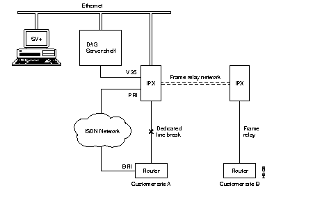
After validating the ANI, the DAS (INS) Daemon has StrataView Plus delete the Normal connection associated with this ANI. Using the Dial-Backup connection information in its database, StrataView Plus then adds the dormant Dial-Backup connection to Customer Site B. The DAS Dial-Up Frame Relay application monitors the Dial-Backup connection for disconnects so it can remove the connection (PVC) when it is no longer needed. It will also restore the Normal frame-relay connection configured for the original dedicated line. In addition, the DAS Server Shelf also collects Call Detail Records (CDRs) for the Dial-Up connection, which are read and retrieved by the StrataView Plus Workstation. (Appendix D contains further information about Call Detail Records.)
A Dial-Backup connection requires three steps:
Step 1 Configuring an ANI with ANI Type set to Dial-Backup (This step is done using the INS/DAS ANI Configuration option from the StrataView Plus Main Menu and was covered in Chapter 11, Configuring Automatic Number Identifiers.)
Step 2 Configure a Dial-Backup Connection with the StrataView Plus Connection Manager.
Step 3 Configure a Normal Frame Relay PVC with the StrataView Plus Connection Manager and "Associate" it with the Dial-Backup Connection.
This chapter provides procedures for using the Connection Manager window tools to configure Dial-Backup connections, i.e, add dormant Dial-Backup connections to the StrataView Plus database and associate them with Normal frame-relay connections.The examples in this chapter are taken from StrataView Plus 8.1; the procedures for StrataView Plus 8.4 are nearly identical. Where there are significant differences between StrataView Plus 8.1 and StrataView Plus 8.4, they will be pointed out.
After the INS (DAS) CLI and ANI Configuration Interface parameters are set, you use the StrataView Plus Connection Manager to add the Dial-Backup connection (i.e., dormant frame relay PVC) to the database.
To access the StrataView Plus Connection Manager, follow these steps:
Step 1 Start StrataView Plus.
Step 2 Select 3 to Start Desktop.
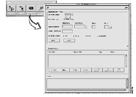
Step 3 Select the Connection Manager icon from the StrataView Plus Desktop toolbox. The Connection Manager menu, shown in Figure 13-2 appears. (The Connection Mode field shown with the Normal or Dial-Up option pulled down normally only shows Normal, the default Connection Mode.)
To add a Dial-Backup connection, follow these steps:
Step 1 In the Connection Manager window, click on the Connection Mode button (Normal or Dial-Up) and select Dial-Up. The ANI Help List window, shown in Figure 13-3, appears. (The ANI Help List window lists all the ANIs that were configured with the INS/DAS ANI Configuration menu described in Chapter 11, Configuring Automatic Number Identifiers.) Also when you select Dial-Up mode, the Connection List Filters section of the Connection Manager window changes. The ANI field replaces the Normal Connection Mode, Local Information, Remote Information, and Connection Status fields.)
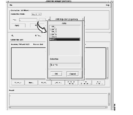
Step 2 Select the ANI from the ANI Help List and click the OK button. (This ANI must be configured as ANI Type: Dial-Backup with the ANI Configuration Interface menu described in Chapter 5.)
Step 3 Click the Apply button on the Connection Manager window. (If there are any Dial-Up or Dial-Backup connections configured for this ANI, they will appear in the Connection List window.)
Step 4 New Dial-Backup connections are added slightly differently in StrataView Plus 9.1 and StrataView Plus 8.4:

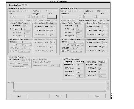
Step 5 Complete the New Dial-Backup (for Release 8.1) or new ANI FR-FR Connection (for Release 8.4) menu for frame-relay parameters:
Step 6 After you have entered your Dial-Backup connection parameters, click the Apply button. The result field of this window should read Connection Addition Successful.
Step 7 Click the Cancel button to exit this window and return to the Connection Manager window. The new connection should appear in the Connection List field. If not, press the Refresh button to view connection information.
To associate a Normal frame relay connection with a Dial-Backup connection, follow these steps:
Step 1 From the StrataView Plus Desktop, open the Connection Manager and select Normal Connection mode.
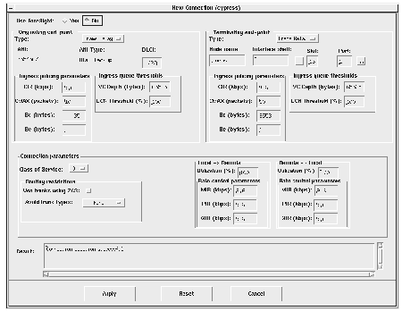
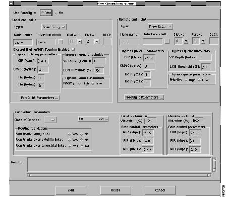
Step 2 If there is not already a Normal Frame Relay connection that you wish to "Associate" with the Dial-Backup connection, click on the New button on the bottom of the Connection Manger window. The Normal New Connection window, shown in Figure 13-7, appears.
Step 3 Complete the Normal frame-relay New Connection window as described in the StrataView Plus Operations Guide. When the Normal frame-relay connection parameters are correct, click on the Add button. A Connection Addition Successful message should appear in the Result window. Click on the Cancel button to return to the Normal Connection Manager window.
Step 4 On the Normal Connection Manager window, shown in Figure 13-2, specify the Local Information (node.slot.port) and Remote Information (node name) for connection you want to associate with a Back-Up connection. Click on the Apply button and all connections which match the filter criteria appear in the List Connections box.
If no connections appear in the Connection List box, be sure that you have specified one or more Connection Status types: OK, Failed, Down, Incomplete.
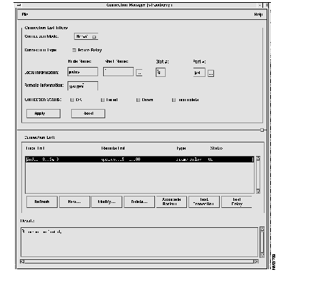
Step 5 In the Connection List box, click on the connection to which you wish to Associate a Dial-Backup Connection. When selected the connection will be high-lighted as shown in Figure 13-8.
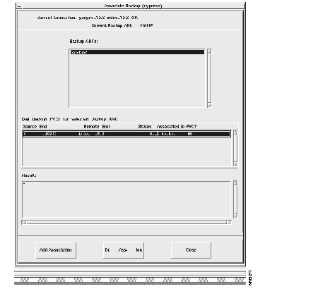
Step 6 Press the Associate Backup... button to access the Associate Backup window, shown in Figure 13-9. The Backup ANI's box will list all the ANIs that have been configured with ANI Type: Dial-Backup as described in Chapter 5. The Dial-Backup PVCs for Selected Backup ANI box will list the Dial-Backup connections that have been configured for that ANI.
Step 7 Select the appropriate ANI and the appropriate Dial Backup PVC and press the Add Association button.
Step 8 Click the Close button to return to the Connection Manager window
|
|