|
|

Table Of Contents
Preliminary Steps Before Installing
Maintaining Safety with Electricity
Installing a BPX Switch Shelf, Preliminary Steps
Preliminary Steps Before Installing
Before proceeding with the installation of the BPX switch, use the following preliminary steps to ensure safety and reliability:
Warning
Installation should be performed by authorized personnel only.
Site Preparation
The following are the requirements for the site preparation:
•
•
80 inches (203.2 cm) deep to provide sufficient clearance around the cabinet to allow access to the front and back.•
•
•
•
(97 Kgs). A fully-loaded DC-version BPX switch can weigh up to 163 pounds (74 Kgs).Parts Checklist
Before proceeding, go through this parts checklist to verify that all the parts you ordered are present, and that they are all in good condition. If there is anything missing or damaged, report it to your Cisco Order Administration representative.
Plug-in cards may be shipped installed or under separate cover. The exact number of cards will vary from site to site, depending on the selected configuration.
The BPX switch is shipped with all unused slots covered by backplane inserts that prevent radio frequency emissions from the equipment. The unit must not be operated with any unused slots left uncovered.
Refer to this list to check the number and type of cards shipped against the number and type of card you ordered. Check that:
Note
Safety Requirements
This section details safety information for system planners, installers, and maintenance personnel.
The mechanical design of the BPX switch prevents any access to exposed voltages without the use of tools. When installed properly, all front and rear cards are mechanically held captive.
Warning
CEPT Requirements
All apparatus (such as, 48 VDC power supplies) connected to the BPX switch must comply with BS6301 or EN60950.
EMI Requirements
Compliance with emission regulations depends upon adherence to the installation steps in this manual, including installation of faceplates for all slots and the use of shielded cables between systems.
Laser Safety Guidelines
The optical ports contain an information label as shown in Figure 7-1.
Figure 7-1 Laser Information Label
Warning
Warning
Warning
Maintaining Safety with Electricity
You must install your BPX switch in accordance with national and local electrical codes.
United States: National Fire Protection Agency (NFPA) 70, United States National Electrical Code.
Canada: Canadian Electrical Code, C22.1, part 1.
Other countries: International Electrotechnical Commission (IEC) 364, part 1 through part 7.
The BPX switch operates safely when it is used in accordance with its marked electrical ratings and product usage restrictions.
Basic Guidelines
The following are the basic guidelines when working with any electrical equipment:
•
•
•
•
•
•
•
Any list of guidelines may not address all potentially hazardous situations in your working environment so be alert and exercise good judgment at all times.
The following are the safety guidelines that will help to ensure your safety and protect the equipment:
•
•
•
•
•
•
Power and Grounding
To access power and grounding requirements, use the following procedure:
Step 1
Step 2
Step 3
Step 4
Step 5
Note
Step 6
Note
Step 7
Mechanical Installation
Caution
Horizontal Positioning
BPX switch shelves are designed to be mounted to two sets of vertical mounting rails in either a Cisco cabinet or a standard 19-inch equipment rack with unrestricted front to rear air flow. When installed in a Cisco cabinet (see Figure 7-2), the front flanges of the BPX switch are secured to the front rails of the Cisco cabinet. In factory installations, rear support is provided by rear mounting rails in the cabinet at a setback of 19.86 inches. As an option, a rear set of rails located at a setback of approximately 30 inches may be used for rear support.
Figure 7-2 Cabinet Mounting Options for the BPX Shelf
BPX switch shelves can also be mid-mounted to an open T-Rail type rack (see Figure 7-3) with unrestricted front to rear air flow. To facilitate this type of installation, brackets may be fastened to the BPX switch shelf at a 5 or 10 inch setback for supporting the front of the BPX switch shelf. Additional rear mounting support is also recommended. Contact Cisco Customer Service for further information.
Figure 7-3 BPX Shelf and T-Rail (Open Rack) or Equivalent Mounting Options
Vertical Positioning
For recommended typical equipment configurations in a Cisco cabinet, see Chapter 2, "BPX Switch Physical Overview."
Installing a BPX Switch Shelf, Preliminary Steps
The BPX switch shelf is designed for mounting in a standard 19-inch (48.25 cm) equipment rack such as the standard Cisco cabinet. A minimum width between rails of 17.750 inches (44.45 cm) is required (see Figure 7-4 and Figure 7-5).
Figure 7-4 Rack Mounting Dimensions, DC Powered Shelf
Figure 7-5 Rack Mounting Dimensions, AC Powered Shelf
Mounting flanges are permanently attached to the front edge of the BPX switch shelf.
Note
The following are the two types of BPX switch shelves with special installation requirements:
•
•
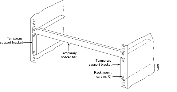
Temporary support brackets and a spacer bar are furnished to ease installation by supporting the BPX shelf as you slide it into a cabinet.
Note
These instructions apply to a BPX switch shelf installation in a Cisco cabinet, which has rear rails at 19.86 inches (50.5 cm) or in a customer supplied standard 19-inch (48.25 cm) equipment rack with rear rails at a 30 inch (76.2 cm) setback.
The recommended stacking order, from the bottom, up, is:
1.
2.
3.
Gap between the shelves is designed to be .060" minimum to allow clearance for replacement.
The first of the two following procedures is the recommended method for installing the BPX shelf and other shelves in a Cisco cabinet: by leaving in the cards and using a lifting device to raise the fully loaded unit into position. The second procedure describes removing all cards for situations where no lifting device is available.
To install the fully loaded BPX switch shelf in a Cisco cabinet by means of a lifting device, use the following procedure:
Step 1
Step 2
Step 3
Step 4
Note
Step 5
Step 6
To install the BPX switch shelf in a Cisco cabinet without use of a lifting device, use the following procedure:
Step 1
Step 2
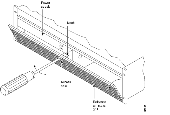
Step 3
a.
b.
c.
d.
Caution
e.
Figure 7-6 Removing an Air Intake Grille
Step 4
Step 5
Note
Figure 7-7 Temporary Spacer Bar and Support Brackets Installation
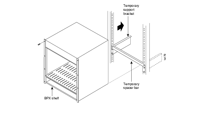
Figure 7-8 BPX Switch Shelf Aligned with Temporary Support Brackets and Bar
Step 6
Step 7
![]()
![]()
![]()
![]()
![]()
![]()
![]()
![]()
Posted: Tue May 10 21:07:00 PDT 2005
All contents are Copyright © 1992--2005 Cisco Systems, Inc. All rights reserved.
Important Notices and Privacy Statement.