|
|

This chapter explains how to set-up a temporary terminal or network management station for initial power-up, and how to attach other peripherals:
A network must have at least one connection to a control terminal or Cisco WAN Manager network management workstation. You use the Cisco WAN Manager network management workstation to configure and maintain all nodes in a network and report network statistical data.
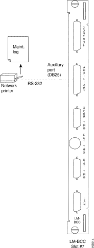
A network printer may be connected to the AUXILIARY port if you wish to print.
If you want to have Cisco Customer Service perform remote troubleshooting, you must attach a dial-in modem to the network. See Connecting Dial-In and Dial-Out Modems
Before proceeding to this chapter, you should first complete the procedures in:
and before that, the procedures in either:
and before that, the procedures in either:
Before attempting to attach equipment to the BPX switch, read the manufacturer's literature to ensure that you have made the equipment ready for attachment.
For additional information, refer to these sources:
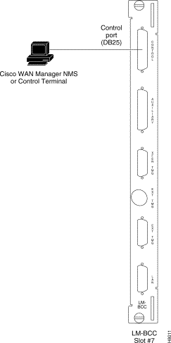
You will need to connect a basic VT-100 type terminal (or PC or workstation, including a Cisco WAN Manager workstation) to the BPX's CONTROL port for use in entering commands to bring up a new node. This temporary or local control is especially useful during installation, initial power-up, and configuration.
To support the Cisco WAN Manager workstation, the BPX switch's LM-BCC back card offers these ports for attaching peripherals:
A Cisco WAN Manager workstation is recommended for managing a network containing the IGX and BPX switches. Refer to the Cisco WAN Manager Operation Manual and Cisco WAN Manager Installation Manual for setup instructions and specifications for the Cisco WAN Manager network management system, which is required to provide network alarm, control, and statistics monitoring.
 |
Note For network management, a Cisco WAN Manager workstation must be connected to the
LAN port of one or more network nodes, typically BPX switches because of their
processing power, to provide network management. It is not connected to the Control Port during normal operation. |
Refer to Table 15-1 for configuration data for the BPX CONTROL port.
)
| Parameter | Setting |
|---|---|
BPX switch Port Used: | Serial CONTROL port, located on a BCC back card, is used to interface to a local terminal. |
Code: | Standard 7 or 8-bit ASCII; 1 or 2 stop-bits; even, odd or no par-ity. |
Interface: | RS-232 DCE. |
Data Rate: | All standard asynchronous data rates from 300 to 19200 bps, independently software-selectable. |
Supported Terminals: | Any terminal compatible with DEC VT-100. |
Cable Required: | Straight-through RS-232 cable. |
The BPX Control and Auxiliary ports are pinned as RS-232/V.24 DCE ports. When connecting a terminal, PC, or other device pinned as RS-232/V.24 DTE to the Control or Auxiliary port, you may use a straight-through cable. However, to connect a modem to the Control or Auxiliary ports, you must use a null-modem cable.
In these procedures:
To attach a terminal to the BPX switch:
Step 2 For nodes with a single BCC: Locate the CONTROL port connector on the LM-BCC in slot 7.
Attach the RS-232/V.24 cable as shown in Figure 15-1, then proceed to Step 5.
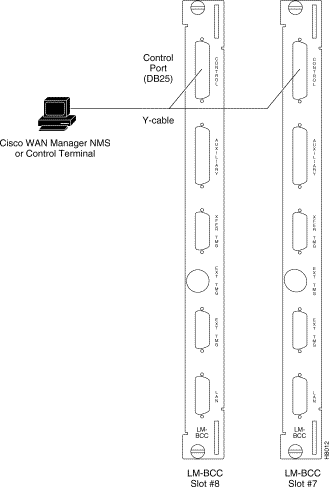
Step 3 For nodes with redundant BCCs: A single cable is sufficient for temporarily connecting to the CONTROL port of the active BCC during initial node configuration. However, if you want to monitor the switchover function of the BCCs via the CONTROL port without swapping the cable from the CONTROL port of one BCC to the CONTROL port of the other, you can use a Y-cable.
Connect one leg of the Y-cable to the CONTROL port connector on the backcard in slot 7 and the other leg to the slot 8 CONTROL port connector.
Step 4 Attach a RS-232/V.24 cable to the remaining leg of the Y-cable as shown in
Figure 15-2.
Step 5 Fasten the cable connector to the CONTROL port connector with the captive screws on the connector hood.
Step 6 Plug the control terminal (or Cisco WAN Manager) power cord into the appropriate wall receptacle (115 VAC or 240 VAC) and switch it on.
Step 7 If connecting to a Cisco WAN Manager workstation, set the port function for VT100/StrataView by using the cnftermfunc command.
If using a "dumb" terminal, select VT100 only (# 5).
Step 8 Make sure that the CONTROL port and the terminal or workstation are set to the same baud rate and check the other communication parameters by using the cnfterm command.
Step 9 When you have completed the initial node configuration, remove the connections to the CONTROL Ports. Network Management connections are described in the next section.
|
Note When a node is powered up, it enters "boot mode" which has a default speed of 9600 bps. If the node's control port has been previously configured to 19,200, the first messages will appear garbled because the terminal is at 19,200 bps, but the control port (in "boot mode") is temporarily at 9,600 bps. When the "transition to online" occurs, then the speeds will match and the terminal display will be readable. |
After the node receives power and correctly starts up, the terminal screen appears as shown below. If the screen is blank or does not display the initial screen, check all connections to the node, and make sure the terminal and node are receiving power. If the connections are correct, press the Delete key a few times or cycle the terminal power.
gamma          TRM   YourID:1        IGX 8420    9.2      Aug. 15 1998  13:47 CST


Enter User ID:
In most systems, the network printer will be connected to a serial port on the Cisco WAN Manager NMS terminal server. The maintenance log and all statistics data will reside on the Cisco WAN Manager.
However, it is possible to connect a printer to a node and use various BPX switch software print commands to print locally. This may be helpful during the initial network installation phase.
The optional local maintenance printer for the BPX switch is the Okidata Model 184 dot matrix printer. You may connect this printer to any node.
Refer to Table 15-2 and Table 15-3 for printer configuration requirements. Note that the Okidata Model 184 is not the same printer that may be provided with the Cisco StrataView Plus NMS terminal but in addition to it.
| Parameter | Setting |
|---|---|
BPX switch Port Used: | Serial AUXILIARY port, located on the LM-BCC card, is used for the maintenance printer. |
Code: | Standard 8-bit ASCII; 8 data bits, 1 stop-bit, odd parity. |
Interface: | RS-232 DCE. |
Data Rate: | 9600 baud. |
Supported Printer: | Okidata 184. |
Cable Required: | Straight-through RS-232 cable. |
DIP Switch A is an 8-section DIP switch located on the printer's main circuit board.
To access the configuration switches, slide back the switch cover at the top, rear of the printer case. Set Switch A as indicated in Table 15-3.
| Switch A | Setting | Description |
|---|---|---|
1 | Off | ASCII with non-slashed zero |
2 | Off | ASCII with non-slashed zero |
3 | Off | ASCII with non-slashed zero |
4 | Off | 11-inch paper length |
5 | On | 11-inch paper length |
6 | Off | No Auto Line Feed. |
7 | On | 8-bit data. |
8 | Off | Enables front panel. |
The High Speed Serial Interface DIP Switch consists of two DIP switches, SW1 and SW2, located on a serial-board attached to the printer's main board.
Set switches 1 and 2 as indicated in Table 15-4 and Table 15-5.
| Switch 1 | Setting | Description |
|---|---|---|
1 | On | Odd parity. |
2 | On | No parity. |
3 | On | 8 data bits. |
4 | On | Ready/busy protocol. |
5 | On | Test select circuit. |
6 | On | Print mode. |
7 | On | Busy line selection. |
8 | On | DTR pin 2 enabled. |
| Switch 2 | Setting | Description |
|---|---|---|
1 | Off | Transmission |
2 | On | Speed = 9600 baud. |
3 | On | Speed = 9600 baud. |
4 | On | DSR active. |
5 | On | Buffer = 32 bytes. |
6 | On | Timing = 200 ms. |
7 | On | Space after power on. |
8 | Don't care | Not used. |
For the pin assignments for the AUXILIARY port on the BPX switch and the recommended RS-232/V.24 cable pinout and printer DIP switch settings, see Chapter 32, BPX Switch Cabling Summary.
To attach the printer to the BPX switch:
Step 2 For nodes with single BCC: Connect the RS-232/V.24 printer cable to the AUXILIARY port on the LM-BCC back card (see Figure 15-3). Go to Step 4.
Step 3 For nodes with redundant BCCs: A Y-cable is required for this application.
Connect one leg of the Y-cable to the AUXILIARY port connector on the LM-BCC in slot 7.
Connect the other leg to the AUXILIARY port connector on the LM-BCC in slot 8.
Step 4 Plug the printer power cord into the appropriate AC outlet (115 VAC or 240 VAC).
Step 5 Set the port function for printer by using the cnftermfunc command.
Step 6 Make sure the control port and the printer are set to the same baud rate and check the other communication parameters by using the cnfterm command.
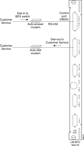
Cisco Customer Service uses modems to remotely diagnose and correct customer problems with installed BPX switches. You will need to connect a modem to each BPX switch to provide remote access.
The modem currently recommended for use with the BPX switch is the Codex Model V.34R. You must use an auto-answer modem
A dial-in connection to a BPX switch RS-232 from customer service via a modem uses the CONTROL port of the BPX switch. This port is bi-directional transmit and receive.
A dial-out connection from a BPX switch via a modem to Cisco Customer Service uses the AUXILIARY port of the BPX switch.
These modems connect to a standard telephone line wall jack. The modem connections require special cables and setup procedures.
If the BPX switch is equipped with redundant BCCs, you must use an RS-232 Y-cable for these connections.
See Table 15-6 for modem interface requirements.
| Parameter | Requirement |
|---|---|
BPX switch Port Used: | CONTROL port on BCC back card is used for auto-answer modem setup. |
Code: | Standard 8-bit ASCII, 1 stop-bit, no parity. |
Interface: | RS-232 DCE. |
Cable to modem: | Null modem cable: CONTROL or AUXILIARY port to modem (DCE to DCE) |
Phone Lines: | Dedicated, dial-up business telephone line for Customer Service-to-BPX switch modem. |
Data Rate: | All standard asynchronous data rates from 300 to 19200 bps, independently software-selectable. |
Supported Modems: | Motorola V.34R 28.8 baud modem with or without talk/data button. |
This setup procedure allows Cisco Customer Service to dial in to your BPX switch to provide support and troubleshooting:
Step 2 Using the cnftermfunc command, set the terminal type to VT100/StrataView.
Step 3 To program the modem, temporarily attach a terminal to the modem using a straight through RS-232 cable (DTE to DCE). The modem EIA port will automatically match the 9600 bps setting of the terminal.
Step 4 Enter the commands listed in Table 15-7 to set up the modem for proper operation.
|
Note Consult the manual supplied with your modem for specifics concerning the modem configuration. Call Cisco Customer Service for latest modem configuration information. |
Step 5 Disconnect the terminal and the straight-through cable from the BPX CONTROL port.
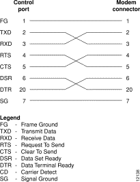
Step 6 Connect the modem to the BPX CONTROL port by using null-modem cables Figure 15-5. A null modem cable is used because the connection is essentially a DCE to DCE rather than a DTE to DCE connection.
Step 7 Ask Cisco Customer Service to assist in testing the operation of the modem setup.
| Step | Command | Function |
|---|---|---|
1. | AT & F | Reset to factory default. |
2 | ATL1 | Set modem loudness, modem speaker at low volume. |
3. | ATSØ=1 | Enables Auto-Answer Mode on modem (answer on first ring). |
4 | AT\N3 | Enables automatic MNP error correction. |
5 | AT%C | Disables data compression. |
6. | AT\QØ | Disables XON/XOFF flow control. |
7. | AT&S1 | Sets DSR to "normal". |
8. | ATEØ | Disables local character echo. Modem will not echo what you type. |
9. | ATQ1 | Disables result codes. (Modem will appear "dead", will stop responding "OK" to commands.) |
10. | AT&W | Saves current configuration settings in non-volatile memory. (Writes and stores to configuration location 1.) |
This setup procedure enables your BPX to dial up Cisco Customer Service.
Step 2 Using the cnftermfunc command, select option 7, "Autodial Modem"
Enter the customer service-designated Network ID and the customer service modem phone number.
Step 3 Attach a 9600 bps terminal to the modem by using a straight-through cable. The modem EIA port will automatically match the 9600 bps setting of the terminal.
Step 4 Enter the commands listed in either Table 15-8 (V.34R modem without talk/data pushbutton) or Table 15-9 (V.34R modem with talk/data pushbutton), to set up the modem for proper operation.
|
Note Consult the manual supplied with your modem for specifics concerning the modem configuration. Call customer service for latest modem configuration information. |
Step 5 Disconnect the terminal and the straight-through cable from the CONTROL port.
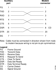
Step 6 Connect the modem to the AUX port by using a null modem cable Figure 15-6.
Step 7 Ask Cisco Customer Service to assist in testing the operation of the modem setup.
| Step | Command | Function |
|---|---|---|
These configuration commands are for a V.34R modem that does not have a talk/data pushbutton. | ||
1. | AT&F | Initializes factory defaults. |
2. | ATL1 | Modem speaker at minimum volume. |
3. | AT*SM3 | Enables automatic MNP error correction. |
4 | AT*DC0 | Disables data compression. |
5. | AT*SC1 | Enables DTE speed conversion. |
6. | AT*FL1 | Enables XON/XOFF flow control. |
7. | AT*SI1 | Enables 5-minute inactivity disconnect. |
8. | AT&C1 | DCD controlled by modem. |
9. | AT&D2 | Modem disconnects when toggles DTR. |
10. | AT&V | Verify entries. |
11. | AT&W | Saves current settings to non-volatile memory. |
*
| Step | Command | Function |
|---|---|---|
These configuration commands are for a V.34R modem that has a talk/data pushbutton. | ||
1. | AT&F | Initializes factory defaults. |
2. | ATL1 | Modem speaker at minimum volume. |
3 | AT\N3 | To enable MNP error correction. |
4 | AT%C | To disable data compression. |
5 | AT\J | Enables DTE speed conversion. |
6 | AT\Q1 | Enables flow control. |
7 | AT\T3 | Enables 3-minute inactivity timer. |
8. | AT&C1 | DCD controlled by modem. |
9. | AT&D2 | Modem disconnects when toggles DTR. |
10. | AT&V | Verify entries. (shows current configuration). |
11. | AT&W | Saves current settings to non-volatile memory. |
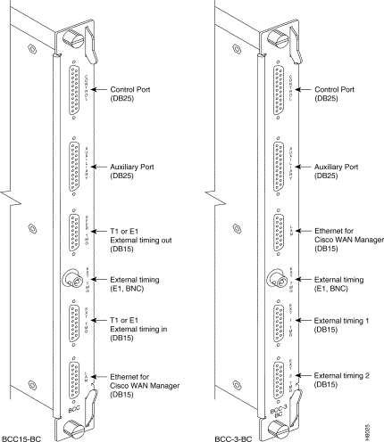
If you want to synchronize the BPX switch to some other external equipment or a local digital central office, you can use one of two connectors on an BCC15-BC or BPX-BCC-3-BC backcard to accept a clock input.
You can use a DB15 connector labeled EXT TMG to connect a balanced T1 or E1 signal, synchronized from some higher-level source to the BPX switch. If an unbalanced 75-ohm E1 signal is available as the timing source, a BNC EXT TMG connector is also provided.
For a BCC-3-BC backcard (backcard for BCC-3-32M, BCC-3-64M, or BCC-4V), you can use a DB15 connector labeled EXT 1 TMG to connect a balanced T1 or E1 signal, synchronized from some higher-level source to the BPX switch.
The EXT 2 TMG connector provides a redundant connector to EXT 1 TMG. A T1 source with 100 ohm impedance or an E1 source with 100/120 ohm impedance typically uses this connector. If an unbalanced 75-ohm E1 signal is available as the timing source, a BNC EXT TMG connector is also provided.
The BPX switch can use these inputs rather than its internal Stratum 3 clock source.
|
Note Contact Cisco Customer Service for information on setting up either a 75-ohm or 120-ohm clock interface on the BCC backcard. |
![]()
![]()
![]()
![]()
![]()
![]()
![]()
![]()
Posted: Fri Jul 27 16:03:32 PDT 2001
All contents are Copyright © 1992--2001 Cisco Systems, Inc. All rights reserved.
Important Notices and Privacy Statement.