|
|

This chapter provides information on the following features in this release:
This section describes how each feature supports feature mismatch situations in Release 9.2 IGX/BPX switch software. Refer to the 9.2 release notes for up-to-date information on feature support, and software, hardware, and firmware requirements.
This section provides some general guidelines for feature mismatching on the IGX and BPX in Release 9.2. These features perform feature mismatching functions:
The following areas in switch software support feature mismatching:
All configuration commands that enable Release 9.2 features support mismatch verification. For example:
Feature mismatching provides customers a graceful migration path to Release 9.2 features. Switch software Release 9.1 and previous releases of switch software will mismatch cards if the capabilities in the logical card database do not match exactly the capabilities of the physical card. Such a restriction would not allow customers to gracefully migrate their BXM/UXM cards.
In this release, the feature mismatching capability will not mismatch cards unless the actual feature has been enabled on the card. This allows for a graceful card migration from an older release.
Switch software provides an upgrade path for each of the Release 9.2 features. Table 18-1 below describes the various scenarios while running Release 9.2 switch software and various versions of Release 9.1 and Release 9.2 firmware. Table 18-1 also describes the process of upgrading firmware in a scenario where a single active card and Y-cable is in use.
| Configuration/Features | VSI | VT | LMI/ILMI | APS | OAM |
|---|---|---|---|---|---|
Single Active Card Configuration: if the firmware is upgraded from 9.1 to 9.2, no mismatch will occur. | N.A. See Note 1 below table.) | OK | OK | OK | OK |
Single Active Card Configuration: if the firmware is downgraded from 9.2 to 9.1, mismatch will occur if the 9.2 feature has been configured. | MM (if VSI is configured) | MM (if VT is configured) | MM (if Card based LMI is configured) | MM (if APS is configured) | MM (if OAM is configured) |
Y-cable configuration with the Primary Card running 9.1 firmware and the Secondary Card running 9.2 firmware: the Primary Card will mismatch if the 9.2 feature has been configured. | Primary-MM (Primary Card mismatch if VSI Configured) | Primary-MM (Primary Card mismatch if VT feature is configured) | Primary MM (Primary Card mismatch if Card based ILMI is configured) | Primary MM (Primary Card mismatch if APS is configured) | Primary MM (Primary Card mismatch if AOM is configured) |
Y-Cable configuration with the Primary Card and the Secondary Card running 9.2 firmware: no mismatch will occur and the 9.2 features are available to be configured. | OK
| OK
| OK | OK
| OK
|
Y-cable configuration with the Primary Card running 9.2 firmware and the Secondary Card running 9.1 firmware: the Secondary Card will mismatch if the 9.2 feature has been configured | Secondary-MM (Secondary Card mismatch if VSI Configured) | Secondary-MM (Secondary Card mismatch if VT feature is configured) | Secondary MM (Secondary Card mismatch if Card based ILMI is configured) | Secondary MM (Secondary Card mismatch if APS is configured) | Secondary MM (Secondary Card mismatch if OAM is configured) |
Support for up to two partitions requires BPX switch software 9.2.3 and Firmware Ez. The card uses a flag in the capability message to report multiple partition capability. Firmware releases that do not support multiple partitions set this flag. The multiple partitions capability is treated as a card attribute and added to the attribute list.
Use of a partition with ID higher than 1 requires support for multiple VSI partitions in both switch software and BXM firmware, even if this is the only partition active on a the card.
In a y-red pair configuration, the multiple partition capability will be determined by the minimum of the two cards. A card with no multiple partition capabilities will mismatch if any of the interfaces has an active partition with an ID higher than 1. Attempts to enable a partition with an ID higher than 1 in a logical card that does not support multiple partitions will be blocked.
Table 18-2 shows mismatch conditions if the number of channels changes.
| Configurations | Mismatch |
|---|---|
Replacing the current active card with a card with more channels: card will not mismatch, although the additional channels are NOT available to the user. | No |
Replacing the current active card with a card with fewer channels: the inserted card will mismatch. | Yes |
Active or standby Y-cable configuration with both the primary and secondary card supporting the same number of channels as defined in the logical database: no mismatch. | No |
Active Y-cable configuration with the Secondary Card supporting fewer channels than defined in the logical card (primary card) database: the secondary card will mismatch. | Secondary card mismatch |
Active Y-cable configuration with the primary card supporting less channels than the logical card database: the primary card will mismatch. | Primary card mismatch |
Active Y-cable configuration with the primary or secondary cards (or both) supporting more channels then the logical card DB: neither card will mismatch although the additional channels are NOT available to the user. | No mismatch
|
Standby Y-cable configuration with the primary or secondary cards supporting different number of channels: card will mismatch. | Mismatch
|
The following sections describe some of the behavior related to feature mismatching in this release.
The BXM and UXM card insertion/mismatch checking verifies that the inserted card supports all features currently available to the user. For Feature Mismatching, the following verification is performed:
When a feature is enabled, a verification is made to assure that the hardware and firmware supports this feature. That is, during feature configuration, switch software performs a check to determine if the feature is supported by the BXM or UXM card. For example, if you are trying to add APS on a specific line (with addapsln) and the BXM card does not support this feature, a warning message is displayed and the addition is not completed.
The dspcd command gives you mismatch information for the specified card.
If the feature is not available, a warning message is displayed and the feature will not be enabled.
During addyred's mismatch checking, the following verifications are done:
The addyred commands (addyred, delyred, dspyred, prtyred, switchyred) will verify feature support on both the primary and secondary cards.
Following are some things to be aware of related to feature mismatch:
The High Priority (Hi-Pri) login feature provides a solution to ensure that network floods do not cause outages to occur.
The network flooding control feature is an enhancement to switch software that prevents network traffic floods from aborting the processor card and thus keeps the user traffic flowing. Other improvements are included as part of this enhancement to provide additional resilience to the software to ensure that other overload conditions are also handled.
This network flooding control enhancement provides a quick response to outages to networks recently. This enhancement is meant to ensure that multiple node failures no longer occur due to overload conditions that were created in these networks.
A problem occurred that resulted in a flood of network messages being sent to most of the network. The problem was caused by a combination of things on the BPX. A firmware bug caused a standby BXM to loop real traffic back to the bus. An active BXM card in a Y-cable hot standby pair had its firmware upgraded. In doing so, a card switchover occurred which correctly put the card in a standby state but caused all traffic to loop back towards the bus without being blocked. Software had programmed the networking channels on the card so that traffic destined to leave the card would be sent back to the active card. The BPX crosspoint architecture allows standby cards to loop their traffic back to themselves as well as send it to the true destination. The BXM normally rejects cells not destined for the slot they are in except in the case of a hot standby. As a result of these steps, a loop was formed where traffic would loop continuously on the standby card but would also be sent to the active card for transmission out the trunks. This caused a very high rate of duplicate network messages to many nodes downstream from the trunks on this BXM card.
This network traffic flooding resulted in overloading the processor cards at multiple nodes. This overload exhausted critical resources within the processor cards which caused the nodes to abort. The resulting aborts caused CC switchovers but then these processor cards aborted as well. The second abort resulted in derouting all connections at each node.
One factor prolonging the outage was the difficulty in locating and disabling the source of the traffic flood. Aborts continued to occur as the flooding continued. The user interface at each node was unavailable as the nodes serviced the overload of traffic and aborted. This made isolation of the flood difficult. (Physically removing trunk cards at nodes ultimately isolated the source of the flood.)
An additional factor that prolonged the outage was the inability of the routing mechanism to quickly route so many connections at once. The ineffectiveness of the single threaded routing and its backoff collision mechanism led to an unacceptably slow rate of routing (and restoring the user traffic flow). (Manual intervention to shut off routing at key nodes reduced the collision rate and allowed the routing mechanism to efficiently restore all connections.)
This network flooding control enhancement is meant to solve the above problem with the following requirements:
Note that the BXM firmware is expected to be upgraded (carefully) to "W" or beyond to prevent the known flood from reoccurring.
CC: Control Card is the processor card that controls the BPX or IGX nodes. This card runs the AutoRoute networking software.
You do not need to configure anything to get the functionality of the network flooding control feature enhancement or the high priority login feature.
A selected set of features are added to the 8.4 system software to improve the reliability of the software and ensure that network traffic floods do not cause user traffic interruption. The changes are limited in scope to provide a quick fix, minimize the risk of this fix, and to provide compatibility with other 8.4 releases.
The major changes are to prevent similar flooding loopbacks and to prevent the processor card CPU from aborting in the presence of network floods. The secondary changes are to provide a high priority console login to allow you to view and correct flooding problems, and build tolerance into the communication between nodes and between hubs and feeders to allow user traffic to continue flowing when this communication breaks down.
A flood of network traffic can lead to a node becoming unreachable from other nodes in the network. The high priority login feature allows you to log in at the console port and execute a small set of commands. You log in as follows:
Enter User ID: StrataCom
Password: ********
Next Command: hipri
At this point you may detect excessive network messages using the nwstats command or see excessive network handler processing using the dspprf command.
To lessen the CPU use of the network handler task and allow lower priority tasks to execute, you can use the cnfnhparm command to decrease the loop count before the network handler task suspends processing.
If the source of the traffic flood cannot be quickly located and shut off, you can disable LMI error detection using the addfdrlp command on the hub and at all connected feeders. After the network returns to its normal state, you can re-enable LMI at the hub and feeder nodes using the delfdrlp command. You can see the loopback state of the feeder trunk LMI using the dspnode command.
The following subsections describe the individual features in detail.
The network channel programming on the BPX now blocks trunk channels that loop incoming traffic back to the same trunk. This eliminates the possibility that undetected hardware loopbacks create a flood of traffic on the trunk.
For each node in the network there exists one channel on each BPX trunk to receive control traffic for that node and forward it to the one trunk that transmits the traffic for that node. To avoid looping back traffic that unexpectedly arrives on the transmit trunk, a CLP object was set for that channel. On BNI cards the firmware interpreted this to turn off the receive part of the channel. The BXM firmware does not have this functionality. The software now sets the receive VPI/VCI to 0/0. This has the same effect on BXM firmware as the CLP object had on BNI firmware (the receive part of the channel is turned off). The BXM firmware does not sink cells with VPI/VCI equal to 0/0.
The network message handler checks for receiving duplicate network messages without sequence numbers (coerced messages) within a small amount of time. If duplicates are detected, they are quickly discarded without acknowledgment. Duplicates are considered coerced messages received within 1 second of each other. This has the effect of limiting the remaining flow to other parts of the software to 1 coerced message per second. Floods of network messages that use sequence numbers appear as messages with duplicate sequence numbers. Duplicate messages are already handled efficiently. The nwstats screen shows "Dropped flooding msgs".
A configurable limit is added to the network handler to control the number of cells that may be read from the SAR receive queue before giving up the CPU to lower priority tasks. This has the effect of limiting the amount of CPU usage by this high priority task even when floods of network traffic are present. The command and its syntax for controlling this feature are defined below.
The setting of this parameter to a low number may lead to the dropping of network traffic, possibly resulting in comm breaks, comm fails, or background test failures.
A special high priority console user login is created to allow you to log in and execute some commands on the node even during periods of node congestion. The console login executes as high priority before the user logs in. When you log in as "StrataCom" and the first command typed is the new command is hipri, then the user task stays in high priority mode. If the user logs in using another account or uses "StrataCom" but does not use the hipri command first, then the user task reverts to the normal (lower) priority. The following error message is displayed when the hipri command is used by a non-Cisco login.
The following error message is displayed when hipri is not the first command immediately after login.
The following error message is displayed when you try to use command but not from the control port.
The high priority user task executes above all tasks but the resource handler. This allows this feature to execute even in cases of network message flooding, connection routing, extreme CommBus usage, etc.
Notification is given when high priority mode is in use by the "High Priority!" string on the dsplog screen. A sample screen is shown in Example 4 under the "dsplog" section.
Only a subset of the user commands is allowed to run during a high priority login. Due to the high priority of this task, some commands may not work correctly or may affect other features in the system. For that reason, the list of commands is limited and are blocked at the command line. The user receives the following message when an invalid command is attempted from high priority:
Table 18-3 lists the commands allowed in high priority mode for the StrataCom user level:
addfdrlp | bye | cbstats | cbtrace | ccb | cnw |
cnfnhparm | dcb | dcct | delfdrlp | dlcon | dm |
dncd | dspalms | dnib | dnw | dspalms | dspcd |
dspcderrs | dspcds | dsplog | dspnds | dspnode |
|
dspnw | dspprf | dspprfhist | dspqs | dspsust | dspswlog |
dsptrkerrs | dsptrks | dsptrkstats | dsptrkutl | dspusertask | dspusertasks |
dvc | help or "?" | killuser | logoutuser | nwstats | nwtrace |
off1 | off2 | off3 | on1 | on2 | on3 |
pm | resetcd | resetsys | runrev | stopjob | switchcc |
vt | "." (history) |
|
|
|
|
The ARP cache table size has been increased to provide more efficient management of IP to Ethernet (MAC) addresses and prevent processor overloads from excessive ARP messages.
Address Resolution Protocol (ARP) is used by IP hosts on an Ethernet LAN to determine the Ethernet (MAC) addresses of fellow hosts. This protocol will, using Ethernet broadcast packets, allow for mapping an IP address to an Ethernet address. To assist in maintaining the mappings, an ARP cache is usually resident on each IP host. By eavesdropping on ARP messages, each IP host can build its ARP cache quickly and efficiently.
When large numbers of IP hosts are resident on the same physical Ethernet, lots of ARP broadcast messages can be normal. Each new translation of IP address to Ethernet address is placed in a local ARP cache entry on the BPX node. Previously, this ARP cache had a size limit of four entries. In situations where a large number of ARP translations exist on the Ethernet, bumping of ARP cache entries to make room for new entries is necessary. In fact, a sort of thrashing in the ARP cache can occur.
Increasing the table size to 16 entries improves the performance of the processor when more than 4 physical devices are on the same LAN segment. ARP broadcasts are minimized as are updates to the ARP cache. This is expected to address the large number of Cisco WAN Manager workstations that a node can support.
The trunk keep-alive mechanism, also known as the Comm Fail test, allows you to select whether or not connections are derouted on keep-alive time-outs. Previously when the Comm Fail test failed, all connections on the trunk were derouted affecting user traffic. This test runs in addition to the physical line alarm mechanism.
In the event of a network flood, the network handler will inevitably end up dropping numerous network messages. Among these will be messages for the Comm Break and Comm Fail tests, leading to a failure of the tests and the declaration of comm breaks with other nodes and comm fails on its trunks.
To provide more tolerance to a flood of network messages, the Comm Fail test functions so that the default for physical trunks is to leave connections routed in spite of a failure detected by the Comm Fail test. Network alarms and log events are still generated for Comm Fail failures, but connections are not derouted.
In the case of virtual trunks, the Comm Fail test may be the only indication that a virtual trunk crossing an ATM cloud is not passing traffic. For this reason, virtual trunks must continue to de-route connections on Comm Fail failures.
Control of whether Comm Fail test failures cause deroutes on physical trunks is provided by the confounders command. A new parameter Reroute on Comm Fail indicates whether connections should be derouted on failures. If enabled, a Comm Fail test failure on any local trunk results in all nodes rerouting the connections they own that are currently on that trunk. If this is not enabled, a Comm Fail test failure will not result in the rerouting of the connections. A comm fail on a virtual trunk will always result in the rerouting of all the connections on the trunk, regardless of the setting of the enable flag.
Regardless of the Reroute on Comm Fail parameter setting, a trunk that fails the Comm Fail test is still declared as failed. Route-op still runs and will consider this trunk unusable for network traffic. Network clock routing also considers the trunk unusable for clocking and builds a route around this trunk. These operations continue to work as in releases previous to Release 9.2.
The syntax of this command is shown below.
A manual command is added to IGX and AXIS feeder software to allow control over the endpoint connection status. If the BPX cannot communicate LMI messages with its feeders, then the LMI status at the feeders must be maintained to keep the connections "active" to their external devices.
If the BPX hub is flooded with network messages, then LMI/ILMI communication with its feeders may be interrupted. LMI normally runs a keep-alive between the hub node and feeder node. If the keep-alive fails, then the other end changes the status of all connections to "failed". If the outage is only due to a network message flood, then it is desirable to override this mechanism to keep the connection status as "active".
The BPX and IGX software now has the addfdrlp and delfdrlp commands. On the BPX hub with attached feeders, the delfdrlp command clears any communication failures on the specified feeder and sends messages to the remote nodes (the routing nodes for the other end of the feeder connections) informing them of this clearing. In addition, the BPX no longer sends any status updates to the feeder yet it continues to acknowledge any feeder LMI messages received. The dspnode command indicates loopbacks on feeders.
The syntax for addfdrlp is shown below.
addfdrlp <slot>.<port>
port is the port number for the feeder trunk
The following error messages may be displayed.
The BPX command delfdrlp restores the BPX's feeder LMI protocol to the normal state and triggers an update of connection status towards the feeder.
The syntax for delfdrlp is shown below.
delfdrlp <slot>.<port>
where: slot is the slot number for the feeder trunk
The following error messages may be displayed.
The following log messages occurs as a result of using the feeder loopback commands.
On the IPX/IGX feeder, the "addfdrlp" command clears any communication failure on the feeder to the routing node (hub). It also, clears any ingress (coming from the routing node) A-bit failures. In addition, the feeder does not send the routing nodes any status updates but continues to acknowledge any routing node LMI messages received.
The syntax for "addfdrlp" is shown below:
addfdrlp <slot>.<port>
where: slot is the slot number for the feeder trunk
The following error messages may be displayed.
The IGX command delfdrlp restores the routing node's LMI protocol to the normal state and triggers an update of connection status toward the routing node.
The syntax for delfdrlp is shown below:
The following error messages can be displayed:
The implementation of the LMI disabling feature is manual in this release.
Figure 18-1 shows a sample cnfnodeparm screen. More than one screen is needed to show all the parameters for this command.
sw45           TN    SuperUser       BPX 8620    9.2 Aug. 27 1998 18:26 PDT

31 TFTP Write Retries      [    3] (D)
32 SNMP Event logging      [    Y] (Y/N)
33 Job Lock Timeout        [   60] (D)
34 Max Via LCONs           [50000] (D)
35 Max Blind Segment Size  [ 3570] (D)
36 Max XmtMemBlks per NIB  [ 3000] (D)
37 Max Stby Update Q Sz (%)[   33] (D)
38 Stat Config Proc Cnt    [ 1000] (D)
39 Stat Config Proc Delay  [ 2000] (D)
40 Enable Degraded Mode    [N]     (Y/N)
41 Trk Cell Rtng Restrict  [N]     (Y/N)
42 Enable Feeder Alert     [N]     (Y/N)
43 Reroute on Comm Fail    [N]     (Y/N)
44 Auto Switch on Degrade  [Y]     (Y/N)
45 Max Degraded Aborts     [100]   (D)
46 Max Htls Rebuilt Count  [100]   (D)
47 Htls Counter Reset Time [1000]  (D)
48 Send Abit Early         [Y]     (Y/N)
49 Abit Timer Multiplier M [2]     (D)
50 Abit Timer Granularity M [3]    (0)
51 FBTC with PPD Policing  [   N]  (Y/N)


This Command: cnfnodeparm


Enter parameter index:
Figure 18-2 shows a sample dspnode screen.
------------------------------------------------------------------------
sw237          TN    StrataCom       BPX 8620  9.2.3    June 16 1999 05:06 PST

                   BPX 8620 Interface Shelf Information

Trunk    Name      Type          Part Id   Ctrl Id       CntrlVC        Alarm
                                                     VPI   VCIRange
 4.1     VSI       VSI              1         1        1    20 - 34      OK
13.2     SIMFDR0   AXIS             1         2        0    40 - 54      OK


Last Command: dspnode
VP Tunnelling provides the ability to encapsulate a VP connection into a VC connection (VCC) using gateway functions on the UXM module on the IGX nodes, making it possible to use a public ATM PVC service (VCC service).
The Cisco IGX is Cisco's multiservice enterprise WAN switch using ATM technology that consolidates different traffic types. Virtual Trunking enables IGXs to be connected to a VP service offered by a public ATM network, where each virtual trunk uses a corresponding VP. In certain situations, carriers may offer only a VC service to subscribers, which may be more economical than a VP service to carry virtual trunks. The flexible architecture of the IGX facilitates use of virtual trunking over a permanent virtual circuit (PVC) service, thus providing customers with an option to use the public ATM VP or VC service. A virtual trunk using a VP can be encapsulated into a VC connection (VCC) offered by the public network using advanced gateway functions on the IGX, such as simple gateway and cell forwarding gateway.
This section describes virtual trunking over a PVC service (VCC) solution on the IGX using UXM cards, and how to implement VP tunnelling connections on the IGX.
Multiservice wide-area networks are deployed by enterprise customers to consolidate voice, video and data traffic. Traditionally, leased lines are used to connect the multiservice switches in an enterprise backbone. With the widespread availability of public ATM services, customers now have a cost-effective option of interconnecting multiple sites.
Asynchronous Transfer Mode (ATM) is the preferred technology in the WAN for implementing a multiservice backbone due to its bandwidth efficiency, superior performance and guaranteed quality of service (QOS) offering. Compared with time-division multiplexing (TDM), using ATM in the WAN companies can realize 30 to 50 percent total network savings. Cisco's IGX multiservice WAN switches use ATM's superior capabilities to combine bursty or constant-rate data, voice and video onto one enterprise backbone.
The IGX multiservice ATM backbone can be connected using leased lines or the increasing world-wide availability of public ATM services. Using public networks to interconnect IGXs can be more economically attractive than leased lines to achieve scaling of the network and guaranteed QOS delivery.
Virtual trunking (VT) and traffic shaping functionality is an important product differentiator on the IGX in enabling key customer applications over public ATM networks. The Virtual Trunking feature maximizes the use of a single physical ATM interface to connect to several destinations using a public ATM service. For specific information on virtual trunking, and how to set it up in your network, see the "Overview of Virtual Trunking" section.
The prevalent type of service offered to subscribers by public ATM Service Providers for trunking different locations is a Virtual Path connection (VPC), independent of the Virtual Circuits (VC) carried by the VP. In certain situations, the service provider may be unable to offer VP service to its customers, but instead provides a VC service. In such cases, the IGX provides a solution to its customers by enabling virtual trunking over a public ATM PVC service.
This section addresses the scenario when a public ATM carrier provides a PVC service, and describes the virtual trunking implementation on the IGX using this PVC service. A virtual trunk uses a VP connection that is encapsulated into a VC connection using gateway functions on the UXM module, making it possible to use the public ATM PVC service (VCC).
After the explosive successful growth of Frame Relay services in the WAN, customers requiring higher bandwidth and guaranteed QOS agreements for multiservice integration are universally adopting ATM services. To meet the increasing demand for ATM services, carriers and service providers are exploiting the inherent powerful nature of ATM technology and its advanced traffic engineering capabilities to offer cost-effective public ATM services.
Customers deploying IGXs to form a multi-service WAN backbone have an alternate economical means of connection using public ATM service compared with leased lines. The use of public ATM service facilitates speedy provisioning of service level agreements (SLA) and scalable bandwidth levels.
On the other hand, sharing the same public ATM network between different subscribers may raise some security concerns in the minds of customers who wish to control privacy of their networks. It is also mandatory for the customer premise equipment to perform shaping on the traffic entering the public ATM network to conform to the SLA specified parameters. The ingress side of the public ATM network performs traffic policing to ensure that the customer maintains the service level agreements and discards any non-conformant traffic. Public ATM switches reserve adequate bandwidth needed to fulfill the service level agreements, and traffic policing ensures that network-wide congestion is not caused by misbehaving user traffic.
The predominant type of service offered by carriers is the VP service, which is used to trunk different locations. Although in certain cases when the carrier ATM edge switch may be unable to offer a VP service, a less expensive VC service option is provided to customers.
The virtual trunking feature in this release enables IGXs to be connected through a VP service offered by the public ATM network, where each virtual trunk uses a corresponding VP. In some situations, carriers may offer only a VC service to subscribers, which may be more economical than a VP service, to carry virtual trunks. The IGX's flexible architecture facilitates use of virtual trunking over a permanent virtual (PVC) service, thus providing customers with an option to use a public ATM VP or VC service. A virtual trunk using a VP can be encapsulated into a VC connection (a VCC) offered by the public network using advanced gateway functions on the IGX such as simple gateway and cell forwarding gateway.
The Virtual Path tunneling connections for the UXM card give you the ability to encapsulate a virtual path connection (VPC) inside a virtual circuit connection (VCC). This feature provides a solution an application that uses the public ATM network but does not support Virtual Path connections. To create an IGX network using a public ATM network, the UXM virtual trunk feature is required along with the ability to tunnel the virtual trunk traffic across the cloud using Virtual Circuit Connections (VCCs) provided by the ATM cloud.
The virtual trunking feature introduces the capability to provide connectivity for a hybrid network consisting of Cisco nodes through a public ATM cloud. This feature is intended for providing connectivity to an ATM cloud through IGX nodes. The connections at the cloud's access points can be an ATM UNI or ATM NNI interface.
The purpose for virtual path tunneling on UXM cards is to provide the capability to provide the virtual trunking feature set, even when the network cloud doesn't support virtual path connectivity. This way Cisco IGXs can be introduced into a public ATM network supporting ATM-UNI or ATM-NNI interfaces, by using Virtual Circuit Connections (VCCs) provided by the ATM cloud.
This chapter describes how virtual path tunneling connections over UXM virtual trunks on IGX nodes work. You can configure multiple interfaces on a UXM card as either port(s) or trunk(s), so that a single UXM card can have both tunneling connections (on ports) and virtual trunks (on trunks). Part of the VP tunnelling setup involves configuring DAX connections (connections local to the node) on the IGX UXM card.
The virtual path tunneling feature requires the following components, along with the UXM virtual trunking feature. (The Ports and Trunks feature allows you to use this feature with a single UXM interface card along with 9.2.10 switch software.)
If upgrading from Release 9.1, you must upgrade the firmware first, the upgrade the switch software. See the 9.2 release notes for current system and environment requirements for VP Tunnelling feature.
The UXM virtual trunking and VP tunneling features require 9.2.10 switch software. Virtual trunks support requires new UXM firmware. (Refer to the 9.2 Release Notes for information.) The new firmware revisions are backward-compatible with earlier versions of the software, but the Release 9.2 software is not compatible with 9.1 UXM firmware, therefore a UXM firmware upgrade is required for networks running Release 9.2, so that you can use the virtual trunking feature.
Even though network interoperability is supported between Release 9.2 software and 9.1 or 8.5 or 8.4 software, in a network of hybrid releases, you cannot add UXM virtual trunks.
This section provides a brief description of how to set up VP tunnelling. Refer to later sections for step by step procedures.
You set up the Virtual Path Tunneling connection by configuring three UXM ports, one of which you configure as a virtual trunk port, and the other two as line ports. (For information on how to configure a virtual trunk port, refer to the "Setting up a BXM or UXM Virtual Trunk through an ATM Cloud" section.) A physical back-to-back cabling is provided between the virtual trunk port and one of the other line ports. The third port functions as the entry point to the ATM cloud, feeding the VCC provided by the cloud. The ATM cloud provider will provision this VC connection. You add the tunneling DAX connection between the line ports by using the virtual trunk port side as the VP side and the line port (the port at the cloud entry point) as the VC side. After provisioning a similar tunneling connection at the other end of the cloud (VCC), the virtual trunk is added between the virtual trunk ports at both ends of the connections.
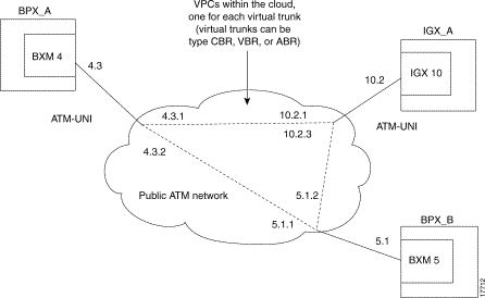
If the ATM cloud is comprised of Cisco nodes (BPX or IGX): for a BPX, the access points are ASI or BXM ports; for an IGX, the access points are UXM ports. If the private ATM cloud consists entirely of Cisco nodes, the Virtual Trunking feature can be used without the tunneling connections, because a cloud consisting of Cisco nodes already supports Virtual Path Connections (VPCs). See Figure 18-3 for an illustration of virtual trunks across a public ATM network. For more information on virtual trunking, and how to set it up in your network, refer to "Overview of Virtual Trunking" section.
This section provides an overview of VP tunnelling and virtual trunking and a description of the setup requirements.
The virtual trunking feature introduces the concept of defining multiple trunks within a single trunk port interface. In the past, trunking has been associated with the physical existence of a trunk card and port. The virtual trunking capability is now extended to UXM trunk cards in Release 9.2 along with the ability to configure ports and trunks on the same interface card. Virtual trunking allows you to define an additional level of trunking within the port resources. This "many-to-one" virtual trunk to port relationship produces a "fanout" trunk capability.
The Virtual Path tunneling solution requires two additional UXM ports (which may not reside on the same card), one of which is connected to the public ATM network, while the other is connected to the virtual trunk port. In addition, a new connection type is supported to allow the virtual path connection (VPC) to tunnel over the public ATM network. This new connection must be used in pair, that is, at both ends of the virtual trunk that attaches to the ATM public cloud.
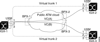
Figure 18-4 shows how an IGX network is connected over a public ATM cloud. Each virtual trunk is connected using a virtual path connection (VPC) across the public ATM cloud. This is how virtual trunks are connected to an ATM cloud that provides a virtual path connection (VPC).
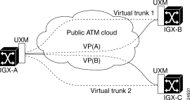
Figure 18-5 illustrates the solution that lets you configure a virtual trunk over a public ATM VC connection (VCC) service.
The addcon command lets you add the virtual path tunneling connection between UXM ports. Similar to the case of virtual trunking, where the virtual path connection should be added before adding the virtual trunks, the Virtual Circuit Connection within the cloud and the tunneling DAX-connection between the two UXM ports have to be provisioned before adding the virtual trunking path between the UXM trunk ports. The connectivity between the UXM virtual trunk side (virtual trunk port) and the Virtual Path side of the port has to be of the same interface type, since they are connected back to back to each other.
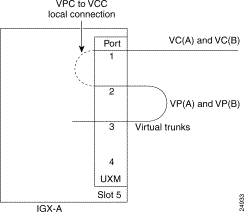
An IGX network is connected using a virtual path connection, as shown in Figure 18-4, where virtual trunks are added between IGX-A and IGX-B/IGX-C. However, a special configuration is implemented at each node to provide tunneling of a virtual path connection over the public ATM cloud, as shown in Figure 18-5. The configuration details at each node is given in Figure 18-6. See Figure 18-7 for an illustration of two additional possible configuration combinations within the same IGX node.

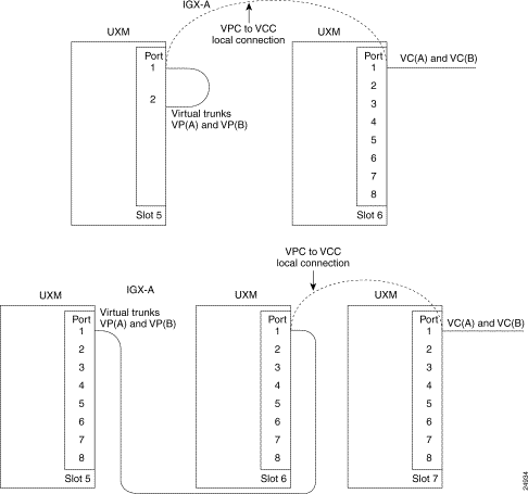
You can add VP tunneling connections between cards residing in the same node, not necessarily on the same slot. Therefore, you can configure this tunneling connection to span across a maximum of three slots, with one trunk port on one slot (as the virtual trunk port), and the other two ports on two different slots as line ports. (See Figure 18-7, the second part of the figure.) You must configure it this way for the interface requirements to be met for connecting a trunk port to a line port back to back. Figure 18-6 shows a VP tunnelling configuration setup with all three ports on the same card, as just described.
Figure 18-7 describes the other two possible combinations within the same node. The first example shows how you can configure a virtual path DAX-connection on one UXM module, creating a VPC to VCC local connection to a port on a UXM module on the same node. This VCC then goes out on the network to the public ATM cloud, with the Virtual Path encapsulated, or "tunnelled", within it. (A DAX connection is connection that is local to the node.)
The second example shows a tunneling connection configuration spanning across a maximum of three slots, with one trunk port on one slot (as the virtual trunk port) and the other two ports on two different slots as line ports, if the interface requirements are met for connecting trunk port to line port back to back.
Y-cable redundancy is also supported with the VP Tunnelling feature. Therefore, each card can have its own Y-redundant pair. In the case where all three ports reside on different cards, each card must be configured with Y-redundancy. The Y-cable setup can be configured as shown in Figure 18-8.

Following are some important feature details that you should know about before configuring VP tunnelling into your network:
At each IGX node accessing the public ATM network, implement the setup on the UXM module identified below and as shown in Figure 18-9.

At each IGX node that interfaces to the cloud, you must perform the similar setup described in the steps below. The following example is illustrated with a private ATM cloud containing BPX nodes with ASI interfaces. See Figure 18-10 for an illustration of VP tunnelling connections within the BPX cloud.
Step 1 Port 3 is used for virtual trunks. (Port 3 is only used for this example—you can configure any port for virtual trunking.) Normally, to use the virtual trunk feature, this port is connected to a public ATM network that supports virtual path connections.
Step 2 Use a cable to connect port 3 to another port (port 2) on the same UXM card, or another UXM card.
The interface type much match so that the line port can be activated on port 2.
Step 3 Connect port 1 to the public ATM cloud. As shown in the example above in Figure 18-10, connect BPX-1 (ASI/BXM) at the cloud to IGX-1 (UXM port 1), with the matching interface types. Repeat the steps for IGX2-BPX2 and IGX3-BPX3 pair. For illustration purposes, assume that the UXMs on all the IGXs are in slot 5, and that the ASIs at the BPXs are in slot 10.
Step 4 Provision the VC within the ATM cloud. If the cloud is comprised of Cisco nodes (such as BPXs), you can provision the VC connection at BPX1 with the addcon command, where there is connectivity available between BPX-1 and BPX-2.
This connection is referred to as VC(a) within the cloud. The bandwidth required for this connection cannot exceed the maximum configurable bandwidth for the UXM virtual trunk.
Similarly provision the VC(b) connection with another addcon command at BPX-1; for example:
The connection just added is referred to as VC(b) within the cloud.
Step 5 Add a local connection between port 2 to port 1 for VP(a) to VC(a), and VP(b) to VC(b). In this example, port 2 is referred as the VP side of the connection, and port 1 is referred to as the VC side of the connection. This new connection will provide an encapsulation function. In this example, the addcon command syntax will look like the following:
You must select the VPI/VCI at the VC side so that it will match up with the VPI/VCI provisioned at the cloud. Also, the VPI at the VP side of the tunneling connection should be selected so that it will match with the VPI configured on the virtual trunk at port 3. Add similar connections at the other ends of the provisioned VC—at IGX-2 and IGX-3.
Step 6 After the VP tunnelling connection is established at both ends, you can add the virtual trunk between the trunk ports 3 as shown in the following sub-steps.
to activate the virtual trunk.
to configure the VPI on this virtual trunk, to be the VPI used for adding the tunneling connection at the VP side. In this example, 1 is the VPI selected for the trunk between IGX-1 and IGX-2. You can configure and activate another trunk, for example (5.3.15), for the VPI value of 3 corresponding to VC(b).
This addtrk command adds the virtual trunk between IGX-1 and IGX-2 (if IGX-2 had similar tunneling connections to that of IGX-1, and is physically attached to BPX-2 at the cloud entry point). Similarly, the virtual trunk 5.3.15 can be added between IGX-1 and IGX-3 (VPI=3).
You can display the trunks at IGX-1 between IGX-2/IGX-3 by using a dsptrks command as follows:
The required connections for the above setup at IGX-2 will be:
and similarly at IGX-3:
Step 7 The back to back cabled ports (Virtual Trunk port and one of the other line ports) should be running the same port interface protocol (UNI or NNI or no protocol). However, this protocol does not need to be the same as the protocol running on the port at the VC side of the tunneling connection.
Step 8 Enable ILMI on port 1 and port 2. These ILMI status changes will be propagated between the VC attached to the cloud and the VP used by the virtual trunk.
Step 9 The VC failure on the cloud has to be propagated to the line ports, so that the endpoints on the IGX side can be conditioned.
The following are known limitations of this feature:
1. Because UXM hardware does not support local switching, twice the amount of UBU is required because cells must visit the bus twice. If necessary, an additional IGX node may be required to implemented VP tunneling.
2. This VP tunneling connection is limited to a local connection only. This VP tunnelling connection is not allowed over any trunk.
3. Clock source must be derived from either the cloud or a external clock source. Clock source cannot be passed over the cloud. This is a known limitation of virtual trunks.
4. There may be a delay of trunk failure detection in case physical failure (for example, LOS) occurs on the port connected to the cloud. Normally, physical failure automatically triggers virtual trunk failure. In our case, the failure is propagated to virtual trunk using ILMI status changes.
5. Note that the Traffic Shaping option may be required on the UXM port connected to the ATM network cloud to maintain the CDV (Cell Delay Variation) of the VC traffic going through the cloud.
6. Additional bandwidth is necessary to be subscribed from the public ATM network for virtual circuit connection as compared to virtual path connection. The efficiency of this solution is approximately at 50%.
There should be no performance impact except for trunk failure due to LOS as described in Item 4 in the "Some Things to be Aware of" section.
UXM trunks use more than one Virtual Interface (Virtual Interface) per physical port: each of these virtual interfaces aggregates a group of traffic-type based queues. On a physical port supporting multiple virtual trunks, one VI is used to support each virtual trunk. The maximum number of virtual trunks per card equals the number of VIs. This is 15 for UXM cards, which can support a maximum of 8000 LCNs. If there are active ports on a UXM card, the number of virtual trunks/interfaces will be reduced accordingly, so that the total number of virtual trunks that can be active is 15.
Two ends of a virtual trunk can have different port interfaces. For example, a virtual trunk supported by a UXM-OC-3 on one end can be supported by a BXM-T3 at the other end. BNI virtual trunks are incompatible with UXM and BXM virtual trunks. UXM and BXM virtual trunks are compatible with each other. The incompatibility is due to the cell formats used by BNI (StrataCom Trunk Interface, or "STI") as opposed to standard ATM cell formats used by BXM/UXM. Virtual trunks support ATM-UNI or ATM-NNI interfaces, and the VPIs that can be used are limited to 1-255 for UNI and 1-4095 for NNI virtual trunks.
The addcon command allows you to add a tunnelling DAX connection. Adding a connection supports one end of the connection as the VP connection, and the other end as a VC connection between different port interfaces of the same card or different cards. You reference the virtual trunk port as <slot>.<port>.<vtrk>. You can configure bandwidth parameters when adding a connection with the addcon command, and upping a connection and downing a connection. The following screens show some of these display changes. All the commands that support the UXM connections are available for VP tunneling connections also. You add the tunneling connection by using the add-on command; for example:
with either end as the VPI or VCI side. If a tunnelling connection is attempted between nodes or non-UXM cards, you will be prompted with error messages.
Following are the dspcons and and dspcon screens, showing the added connections:
sw224          TRM   StrataCom       IGX 8420  9.2.a5    Mar. 5 1999  11:10 PST

 Local          Remote      Remote
 Channel        NodeName    Channel         State  Type     Compress   Code COS
 12.1.1.100     sw224       12.2.1.*        Ok     cbr
 12.2.1.*       sw224       12.1.1.100      Ok     cbr


Last Command: dspcons
sw224          TRM   StrataCom       IGX 8420  9.2.a5    Mar. 5 1999  11:10 PST
Conn:  12.2.1.*          sw224       12.1.1.100         cbr      Status:OK
   PCR(0+1)     % Util    CDVT(0+1)     Policing
   1000/1000   100/100   10000/10000     4/4

Pri: L  Test-RTD: 0 msec
Path:   Route information not applicable for local connections


sw224     UXM:   OK                    sw224     UXM:   OK
          Line 12.2 : OK                         Line 12.1 : OK
          OAM Cell RX: Clear                     NNI:   OK
          NNI:   OK

This Command: dspcon 12.2.1.*
All the statistics supported on a UXM connection will also be supported on the UXM tunneling connections. Event logging, alarm notifications through a Robust message, and TFTP statistics collection are enhanced to support the virtual path tunneling connection. Upon VC connection failure reported from the cloud, the information is propagated to each virtual trunk using the ILMI protocol.
Common Control—The standby updates handle these new types of connections.
SNMP—Provisioning of the VP tunneling connection is supported by SNMP (Cisco WAN Manager). This includes changes to:
Parsing routines to enable VP tunnelling connections are different from previous releases of switch software to be added through SNMP. The MIB has not changed (to support the tunnelling connections).
| MIB Objects Supported | Description of MIB Object | Ranges/Values |
|---|---|---|
atmEndptDesc | String describing this end-point. Contains information about the domain, nodename, slot, port, vpi, and vci for the endpoint. For example, D1.Node1.12.1.100.200, is a valid description. Domain and nodename need not be given but slot, port, and nodename need not be given but slot, port, VPI, and VCI values must exist; 12.1.100.200 is valid. A virtual path connection endpoint of the form 12.1.100.* is also valid. A virtual path tunnelling DAX connection, with one endpoint as VP and other as VC, of the form 12.1.100.*. Node 1.12.2.100.200 is a valid description. For a basis port, the last 4 bits of the VPI must be between 3 and 14. | <string>
|
atmOtherEndptDesc | String describing the remote PVC endpoint. Contains information about the domain, nodename, slot, port, vpi, and vci for the end-point. For example, D2.Node2,10.100.200 is valid description. Nodename, slot, port, VPI and VCI values must exist. A virtual path connection endpoint of the form D2.Node2.10.1.100.* is also valid. A virtual path tunneling DAX connection, with one endpoint as VC and other as VP of the form 12.1.100.100 Node 1.12.2.100.* is a valid description. For a basis port, the last 4 bits of the VPI must be between 3 and 14. | <string> |
![]()
![]()
![]()
![]()
![]()
![]()
![]()
![]()
Posted: Fri Nov 8 07:11:01 PST 2002
All contents are Copyright © 1992--2002 Cisco Systems, Inc. All rights reserved.
Important Notices and Privacy Statement.