|
|

Table Of Contents
Label Switching on the BPX 8650
Commands Used to Configure VSIs
Introduction to Virtual Switch Interface
Viewing Controllers and Interfaces
Enabling VSI ILMI Functionality
Configuring Partition Resources on Interfaces
When Happens When You Add a Controller
What Happens When You Delete a Controller
VSI Slave Redundancy (Hot Slave Redundancy)
Configuring Service Class Templates
Assigning a Service Template to an Interface
Functional Description of Service Class Templates
Structure of Service Class Templates
Configuring the Virtual Switch Interface
VSI Related Parameters and Descriptions
How Channels are Allocated and Deallocated
VSI Commands
Virtual Switch Interface (VSI) is a common control interface for MSSBU switches such as the BPX 8650 and the MGX 8850. Virtual Switch Interfaces (VSIs) allow a node to be controlled by multiple controllers, such as MPLS (Multiprotocol Label Switching, formerly called Tag Switching) and PNNI.
When a virtual switch interface (VSI) is activated on a port, trunk, or virtual trunk so that it can be used by a master controller, such as a SES PNNI or an MPLS controller, the resources of the virtual interface associated with the port, trunk or virtual trunk are made available to the VSI. These control planes can be external or internal to the switch. The Virtual Switch Interface provides a mechanism for networking applications to control the switch and use a partition of the switch resources.
VSI was implemented first on the BPX 8650 in Release 9.1, which uses VSI to perform Multiprotocol Label Switching. Release 9.1 allowed support for VSI on BXM cards and for partitioning BXM resources between Automatic Routing Management (formerly called AutoRoute) and a VSI-MPLS controller. In this release, you can configure partition resources to be shared between Automatic Routing Management PVCs and one VSI control plane, but not both. In this release, you can configure partition resources between Automatic Routing Management PVCs and two VSI controllers (LSC or PNNI).
The second implementation of VSI on the BPX provides the following extended functionality:
•
class of service templates,
•
•
•
•
Caution
Label Switching on the BPX 8650
Label switching enables routers at the edge of a network to apply simple packets (frames), allowing devices in the network core to switch packets according to these labels with minimal lookup activity. Label switching in the network core can be performed by switches, such as ATM switches, or by existing routers.
For more overview information and specific information on how to configure a BPX 8650 switch and a 7200 or 7500 router for MPLS operation, refer to the Cisco BPX Series Installation and Configuration and Cisco BPX 8600 Series Reference.
Commands Used to Configure VSIs
Following is a list of commands you use to configure VSIs. Refer to each specific command description later in this chapter.
•
•
•
•
•
•
•
•
•
•
•
•
•
•
•
•
•
•
•
•
Introduction to Virtual Switch Interface
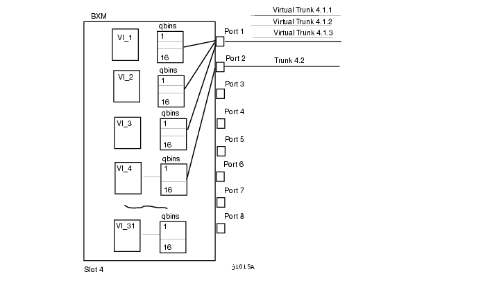
The BXM has 31 virtual interfaces that provide a number of resources including qbin buffering capability. With physical lines and trunks, one virtual interface is assigned to each port.
With virtual trunking, a physical trunk can comprise a number of logical trunks called virtual trunks, and each of these virtual trunks is assigned the resources of one of the 31 virtual interfaces on a BXM. Each virtual trunk equates to a virtual interface. You can enable a virtual switch interface on a port, trunk, or virtual trunk. The virtual switch interface will be assigned the resources of the associated virtual interface. See for an illustration of how BXM virtual interfaces (VIs) map to their associated qbins.
Figure 17-1 BXM Virtual Interfaces and Qbins
Each virtual interface has 16 qbins assigned to it. Qbins 0-9 are used for Automatic Routing Management and 10-15 are available for use by a VSI enabled on the virtual interface. (In Release 9.1, only qbin 10 was used. In this release, the qbins 10-15 support class of service (CoS) templates on the BPX.
Note
Adding a VSI-based (Virtual Switch Interface) controller such as the Label Switching Controller (LSC) to the BPX is similar to adding an MGX 8220 interface shelf to the BPX. For example, you use the addshelf command to add the MPLS (Multiprotocol Label Switching) Controller to any BXM trunk.
You use the vsi option of the addshelf command identify VSI controllers and distinguish them from feeders.
You use addctrlr to add a SES PNNI controller to a BPX node through an AAL5 interface shelf or feeder type configured with VSI controller capabilities. See "Adding a Controller" later in this chapter.
The VSI controllers are allocated a partition of the switch resources. VSI controllers manage their partition through the VSI protocol. The controllers run the VSI master. The VSI master entity interacts with the VSI slave running on the BXMs through the VSI interface to set up VSI connections using the resources in the partition assigned to the controller. If you are adding two controllers that are intended to be used in a redundant configuration you must specify the same partition when you add them to the node by using the addshelf command.
After first using the delshelf command to delete the controller from the network, you then need to down the port and trunk with the dnport and dntrk commands.
VSI Terms and Acronyms
These terms relate to Virtual Switching Interface and MPLS (Multiprotocol Label Switching):
ATM Edge LSRA label switching router that is connected to the ATM-LSR cloud through LC-ATM interfaces. The ATM edge LSR adds labels to unlabeled packets and strips labels from labeled packets.ATM-LSRAn ATM-LSR is a MPLS (Multiprotocol Label Switching) router in which packets are forwarded by switching cells rather than frames, and all packet interfaces are MPLS (Label) Controller-ATM interfaces.
A label switching router with a number of LC-ATM interfaces. The router forwards the cells from these interfaces using labels carried in the VPI and/or VCI field.BCCThe switch control card in the BPX is the Broadband Control Card, which has a 68040 processor.BPXA high-end ATM switch called the Cisco Broadband Packet Exchange (BPX). The BPX is a carrier-quality switch, with trunk and CPU hot standby redundancy.BPX-LSRAn ATM label switch router consisting of a label switch controller (series 7200 or 7500 router) and a label controlled switch (BPX switch).BXMThe Broadband Switch Module (BXM) cards are ATM port cards for the BPX switch that use the Monarch chipset. Various different port configurations are supported by the BXM card: 8ΞDS3, 12ΞDS3, 4ΞOC-3, 8ΞOC-3, 1ΞOC-12 or 2ΞOC-12. The Monarch architecture supports up to 64K bi-directional cross-connect legs per BXM card, although only 16k or 32k options are supported in the first release. The BXM has very flexible input and output queueing facilities, a SAR (Segmentation Assembly and Reassembly) capability, and a MIPS 4650 control processor.Class of Service (CoS) BufferA buffer or queue that serves connections with similar QoS requirements. Also called "qbin" (though a qbin is a platform-specific instance, such as a BXM card, of the more general Class of Service Buffer (CoSB).Class of Service (CoS) Buffer Descriptor TemplateA component of a Service Class Template that contains Class of Service Buffer configurations indexed by CoSB number.
Note
CLIThere are two separate Command-Line Interfaces on the BPX-LSR: One on the BPX itself and one on the MPLS (Multiprotocol Label Switching) Controller. The Control Point integrate these into a single command line interface.CommBusThe CommBus is the BPX's internal messaging protocol. The Switch Control Interface (SCI) that is used by PNNI on the ESP (Extended Services Processor) is based on CommBus messaging accessed through interfaces to the BPX cards.CosBSee Class of Service (CoS) Buffer.ESPThe Extended Services Processor (ESP) is the controller on which the BPX's PNNI implementation runs. It is SPARC-based. The Extended Services Processor 2.0 is an example of an adjunct processor shelf (formerly called an APS). Note that APS, or Automatic Protection Switching, is a feature introduced in Release 9.2.FeederA feeder is a small switch that acts as an extension shelf, typically with lower-bandwidth interfaces, for a larger switch. The larger switch is referred to as the Routing node with the feeder(s) it supports. Collectively, the feeder(s) and routing node form a type of supernode.LC-ATM InterfaceA Label Controlled ATM interface is a MPLS (Multiprotocol Label Switching) interface where labels are carried in the VPI/VCI bits of ATM cells, and where VC (virtual circuit) connections are established under the control of MPLS (Multiprotocol Label Switching) control software.LCNEach interface card in a BPX has a certain number of Logical Connection Numbers. A Logical Connection Number is used for each cross connect leg through the card in question. "LCN" is often roughly synonymous with "cross connect leg". In VSI terminology, an LCN is an example of an Other End Reference.Logical InterfaceEach physical interface and every virtual trunk endpoint on a platform is represented to the VSI controllers as a different logical interface with partitions, and other VSI configuration. Logical Interface numbers are 32-bit with a format which is, in general, known only to the platform.LSRLabel Switching router, which is an MPLS (Multiprotocol Label Switching) router.PNNIPrivate Network-to-Network Interface controller software that runs on the SES hardware platform. The term PNNI controller and SES may be used interchangeably.PortThe VSI makes no distinction between trunk ports and end-point ports. "Port" is synonymous with "Interface".Routing NodeIn tiered networks terminology, a routing node is a larger switch to which one or more feeders is attached. Collectively, the feeder(s) and routing node form a type of supernode.Service Class (aka Service Type)A concept for grouping connections that share a common set of traffic characteristics and QoS requirements. The terms "service class" and "service type" are sometimes used interchangeably.
Note
Service Class databaseThe collection of data items that support the service class template concept, and implemented on a per-VI basis on the BXM. These items include a copy of the specific Service Class Template selected for a VI, as well as additional data as required.Service Class Template (SCT):A set of data structures that map VSI service types to sets of pre-configured VC and Qbin parameters. Consists of two sub-components—a VC Descriptor Template and a Class of Service Buffer descriptor template.VCATM and Frame Relay traffic is carried in Virtual Channels which are set up between adjacent ATM or Frame Relay switches before data transmission occurs. An ATM link between switches may support up to 228 different VCs, although a small number of VCs is reserved for special purposes.VCIEach VC within a specific Virtual Path on a link has a unique Virtual Channel Identifier, which is a 16-bit number.VC Descriptor TemplateA component of a Service Class Template which contains platform-specific VC configurations that are indexed primarily by service type. Together with a Class of Service Buffer (CoSB) descriptor template, it defines a Service Class Template (SCT).VP, VPC, VPIA Virtual Path is a bundle of 216 Virtual Connections with the same Virtual Path Identifier, that is, the first 12 bits of the VPCI. Most ATM switches can switch VPs using only a single cross-connect (instead of up to 216 ). An end-to-end sequence of VPs cross-connected at the intermediate swi5tches is a Virtual Path Connection.VPCIEach VC on a link has a unique Virtual Path and Channel Identifier, which is a 28-bit number. The VPCI consists of a 12-bit VPI concatenated with a 16-bit VCI.Virtual TrunksA Virtual Trunks is a Virtual Path Connection which appears to VSI masters as ordinary trunk (except that the trunk supports 64k VCs at most). In a VSI platform, a virtual trunk endpoint has its own logical interface.VSIVirtual Switch Interface: this is a proposed common control interface to all Cisco MSSBU switches. It embodies both connection management and switch configuration discovery capabilities.VSI 2Virtual Switch Interface, Protocol Version 2: this is revision 2 of a proposed common control interface to all MSSBU switches. It embodies both connection management and switch configuration discovery capabilities.VSI ControllerA controller, such as a PNNI SVC Controller, Portable AutoRoute or Label Switch Controller, which controls a switch using the VSI.VSI MasterA VSI master process implementing the master side of the VSI protocol in a VSI controller. Sometimes the whole VSI controller might be referred to as a "VSI Master", but this is not strictly correct.
1) A device that controls a VSI switch, for example, a VSI Label Switch Controller.
2) A process implementing the master side of the VSI protocol.VSI Slave1) A switch (in the "Single Slave model") or a port card (in the "Multiple Slave Model") that implements the VSI.
2) A process implementing the slave side of the VSI protocol.Adding a Controller
To add a MPLS controller (or a generic VSI controller that does not need AnnexG protocol):
Step 1
Step 2
Step 3
Step 4
Note that addshelf and addtrk are mutually exclusive commands; that is, you can use either addshelf or addtrk, but not both on the same interface shelf.
To add a PNNI controller, use the following commands:
Step 1
Step 2
Step 3
Step 4
Viewing Controllers and Interfaces
Display commands such as dspnw and dspnode show interface shelves.
To view conditions on an interface shelf (feeder) trunk, use:
•
To view conditions of VSI controllers, use:
•
The designation for an MGX 8220 interface shelf is AXIS. The designation for a MPLS (Multiprotocol Label Switching) Controller serving as an interface shelf is LSC. Note that you add a controller in the same way you connect an interface shelf such as an MGX 8220 (AXIS) to a node such as a BPX.
Deleting a Controller
To delete an interface (feeder) shelf, use delshelf. You must first delete the interface shelf or controller to remove the controller from the network, then down the port and trunk with the dnport and dntrk commands.
To delete a MPLS controller or a generic VSI controller that does not need AnnexG protocols:
•
•
To delete a PNNI controller:
Step 1
Step 2
Step 3
Step 4
For more information on adding VSI controllers to BPX nodes, refer to the Cisco BPX 8650 Series Installation and Configuration guide.
Enabling VSI ILMI Functionality
You can enable VSI ILMI functionality both on line (port) interfaces and trunk interfaces. Note that VSI ILMI functionality cannot be enabled on trunks to which feeders or VSI controllers are attached.
To enable VSI ILMI functionality on line (port) interfaces:
Step 1
Step 2
Step 3
Step 4
Step 5
To enable VSI ILMI functionality on physical trunk interfaces:
Step 1
Step 2
Step 3
Step 4
To enable VSI ILMI functionality on virtual trunk interfaces:
Step 1
Step 2
NOTE: ILMI automatically runs on the BXM card for virtual trunks and this is not configurable by using the cnftrk commandStep 3
Step 4
NOTE: VSI ILMI can be enabled for only one VSI partition on trunk interface.To display VSI ILMI functionality on interfaces:
•
Configuring Partition Resources on Interfaces
Prior to Release 9.1, all the LCNs for a BXM card were managed exclusively by the BCC. With the introduction of VSI in Release 9.1 and after, the BCC must allocate a range of LCNs for use by the BXM card.
When configuring resource partitions on a VSI interface, you typically use the following commands:
•
•
•
•
•
•
•
The next step to complete when adding a VSI-based controller such as an LSC (Label Switching Controller) or a PNNI controller is to configure resource partitions on BXM interfaces to allow the controller to control the BXM interfaces. To do this, you must create resource partitions on these interfaces. Use the cnfrsrc command to add, delete and modify a partition on a specified interface.
Note
See for a listing of cnfrsrc parameters, ranges and values, and descriptions. These descriptions are oriented to actions and behavior of the BXM firmware; in most cases, objects (messages) are sent to switch software. Most of these parameters appear on the cnfrsrc screen.
Configuring Qbins
Use the following commands to configure qbins:
•
•
•
Overview of Qbin Templates and How They Are Used by VSI
A qbin template defines a default configuration for the set of qbins for a logical interface. When you assign a template assignment to an interface, the corresponding default qbin configuration is copied to this interface's qbin configuration and becomes the current qbin configuration for this interface. You can then adjust some of the parameters of this configuration on a per-interface basis. Changes you make to the qbin configuration of an interface only affect that interface's qbin configuration, and do not affect the qbin template assigned to that interface.
Qbin templates only deal with qbins that are available to VSI partitions, namely 10 through 15. Qbins 10 through 15 are used by VSI on interfaces configured as trunks or ports. The rest of the qbins are reserved and configured by Automatic Routing Management.
When you execute a dspsct command, it will give you the default service type, and the qbin number.
Configuring the BXM Card's Qbin
When you activate an interface, the default template gets assigned to an interface. The corresponding qbin template gets copied into the card's qbin data structure for that interface. When you want to change this by providing new values using the cnfqbin command, the qbin is now "user configured" as opposed to "template configured". This information is displayed on the dspqbin screen, which indicates whether the values in the qbin are from the template assigned to the interface, or whether the values have been changed to user-defined values.
Qbin Dependencies
The available qbin parameters are shown in . Notice that the qbins available for VSI are restricted to qbins 10-15 for that interface. All 32 possible virtual interfaces are provided with 16 qbins.
Virtual Trunking
In this release, you can configure virtual trunking on the BXM card. Also, VSI controllers let you use BXM virtual trunk interfaces. Using this capability, VSI master controllers can terminate connections on virtual trunk interfaces.
The VSI virtual trunks allows a virtual trunk to be configured as a VSI interface. You configure VSI resources on a virtual trunk using the same command you use to configure physical interfaces. The syntax you use to identify a trunk has an optional virtual trunk identifier that you append to the slot and port information to identify virtual trunk interfaces.
VSI Virtual Trunks in Release 9.2
The VSI virtual trunking feature lets you use BXM virtual trunks as VSI interfaces. You activate and configure VSI resources on a virtual trunk using the same commands you use to configure physical interfaces (for example, cnfrsrc, dsprsrc).
Note
Virtual trunks on the BPX use a single configurable VPI. Because virtual trunk interfaces are dedicated to VSI, the entire range of VCIs is available to the VSI controllers.
Virtual Trunks
The virtual trunking feature introduces the concept of defining multiple trunks within a single trunk port interface. This creates a fan-out capability on the trunk card. Virtual trunking has already been implemented on the BNI cards previous to Release 9.2, and has been extended to work on UXM and BXM cards.
A virtual trunk is a VPC that terminates at each end on the switch port. Each virtual trunk can contain up to 64,000 VCCs, but it may not contain any VPCs. The setup is shown in .
The VSI virtual trunks feature will allow a virtual trunk to be configured as a dedicated VSI virtual trunk. Once VSI is enabled on the virtual trunk, Automatic Routing Management does not include this trunk in its route selection process.
The following is the sequence of events to configure a VSI virtual trunk:
Step 1
Step 2
Step 3
VSI Masters and Slaves
A controller application uses a VSI master to control one or more VSI slaves. For the BPX, the controller application and master VSI reside in an external 7200 or 7500 series router and the VSI slaves are resident in BXM cards on the BPX node ( ).
The controller sets up the following types of connections:
•
•
•
•
•
Figure 17-2 VSI Controller and Slave VSIs
The controller establishes a link between the VSI master and every VSI slave on the associated switch. The slaves in turn establish links between each other ( ).
Figure 17-3 VSI Master and VSI Slave Example
With a number of switches connected together, there are links between switches with cross connects established within the switch as shown in .
Figure 17-4 Cross connects and links between switches
Partitioning
The VSI slaves need to partition the resources between competing controllers: Automatic Routing Management (formerly called AutoRoute) and MPLS (Tag), or Automatic Routing Management and PNNI, for example.
Note
Release 9.1 supports just one VSI controller type. For example, you can configure a partition's resources between an Automatic Routing Management and a VSI-MPLS controller, or Automatic Routing Management and a VSI-PNNI controller, but you cannot configure both a PNNI and MPLS controller. In this release, you can have both a PNNI controller and an LSC-6400 controller, each in its own partition, controlling the same VSI slave.
The resources that you need to configure for a partition are shown in for a partition. The three parameters that need to be distributed are number of logical connections (LCNs), bandwidth (BW), and virtual path IDs (VPI).
Table 17-3 Partition Parameters
lcns
min_lcns
max_lcns
bw
min_bw
max_bw
vpi
min_vpi
max_vpi
The controller is supplied with a logical LCN connection number, that is slot, port, and so on., information that is converted to a logical connection number (LCN).
Some ranges of values available for a partition are listed in :
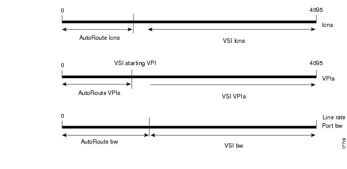
When a trunk is added, the entire bandwidth is allocated to Automatic Routing Management. To change the allocation in order to provide resources for a VSI, you use the cnfrsrc command on the BPX switch. A view of the resource partitioning available is shown in .
Figure 17-5 Graphical View of resource partitioning (Automatic Routing Management and VSI)
Multiple Partitioning
In this release, you can configure partition resources between Automatic Routing Management PVCs and two VSI controllers (LSC or PNNI). Two VSI controllers in different control planes can independently control the switch with no communication between controllers. The controllers are essentially unaware of the existence of other control planes sharing the switch. This is possible because different control planes used different partitions of the switch resources.
You can add one or more redundant LSC controllers to one partition, and one or more redundant PNNI controllers to the other partition. Two new templates have been added for interfaces with multiple partitions controlled simultaneously by a PNNI controller and an LSC.
The master redundancy feature allows multiple controllers to control the same partition. In a multiple partition environment, master redundancy is independently supported on each partition.
These limitations apply to multiple VSI partitioning:
•
•
•
•
•
•
Compatibility
The card uses a flag in the capability message to report multiple partition capability. Firmware releases that do not support multiple partitions set this flag off. The multiple partitions capability is treated as a card attribute and added to the attribute list.
Use of a partition with ID higher than 1 requires support for multiple VSI partitions in both switch software and BXM firmware, even if this is the only partition active on a the card. In a y-red pair configuration, the multiple partition capability is determined by the minimum of the two cards.
A card with no multiple partition capabilities will mismatch if any of the interfaces has an active partition with ID higher than 1. Attempts to enable a partition with ID higher than 1 in a logical card that does not support multiple partitions will be blocked.
Multiple Partition Example
Each logical switch can be seen as a collection of interfaces each with a set of resources associated with it. Consider a BPX switch with 4 interfaces 10.1, 10.2.1, 11.1 and 11.7.1. Also assume the resource partitioning in .
Figure 17-6 Virtual Switches
Three virtual switches are defined by this configuration:
AutoRoute :
10.1: 2000 lcns, 20000 cps, vpi: 1-199;
10.2.1: 10000 lcns, 10000 cps, vpi 200;
11.1: 2000 lcns, 100000 cps, vpi: 1-199}Partition 1:
10.1: 4000 lcns, 30000 cps, vpi: 200-239;
11.1: 3000 lcns, 50000 cps, vpi: 200-249;
11.7.1: 5000 lcns, 200000 cps, vpi: 250-250}Partition 2:
10.1: 4000 lcns, 20000 cps, vpi: 240-255;
11.1: 4000 lcns, 10000 cps, vpi: 250-255}Resource Partitioning
A logical switch is configured by enabling the partition and allocating resources to the partition. This must be done for each of the interfaces in the partition. The same procedure must be followed to define each of the logical switches. As resources are allocated to the different logical switches a partition of the switch resources is defined.
The resources that are partitioned amongst the different logical switches are:
•
•
•
Resources are configured and allocated per interface, but the pool of resources may be managed at a different level. The pool of LCNs is maintained at the card level, and there are also limits at the port group level. The bandwidth is limited by the interface rate, and therefore the limitation is at the interface level. Similarly the range of VPI is also defined at the interface level.
You configure the following parameters on a VSI partition on an interface:
•
•
•
•
•
•
Partitioning between AutoRoute and VSI
In addition to partitioning of resources between VSI and AutoRoute, multiple partitioning allows sub-partitioning of the VSI space amongst multiple VSI partitions. Multiple VSI controllers can share the switch with each other and also with AutoRoute.
The difference between the two types of partitioning is that all the VSI resources are under the control of the VSI-slave, while the management of AutoRoute resources remains the province of the switch software.
Figure 17-7 Resource Partitioning Between AutoRoute and VSI
These commands are used for multiple partitioning:
•
•
•
•
VSI Master and Slave Redundancy Functional Overview
This release supports the ability to have multiple VSI controllers (referred to as VSI master redundancy). This master redundancy feature enables multiple VSI masters to control the same partition.
You add a redundant controller by using the addshelf command, the same way you add an interface (feeder) shelf, except that you specify a partition that is already in use by another controller. This capability can be used by the controllers for cooperative or exclusive redundancy:
•
•
The switch software has no knowledge of the state of the controllers. The state of the controllers is determined by the VSI entities. From the point of view of the BCC, there is no difference between cooperative redundant controllers and exclusive redundant controllers. Refer to for illustrations of a VSI Master and Slave, and for an illustration of a switch with redundant controllers that support master redundancy.
Switch software supports master redundancy in the following ways:
•
•
•
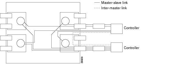
The inter-controller communication channel is set up by the controllers. This could be an out-of-band channel, or the controllers can use the controllers interface information advertised by the VSI slaves to set up an inter-master channel through the switch.
below shows a switch with redundant controllers and the connectivity required to support master redundancy.
Figure 17-8
Switch with Redundant Controllers to Support Master Redundancy
Note
VSI Slave Redundancy Mismatch Checking
To provide a smooth migration of the VSI feature on the BXM card, line and trunk Y-redundancy is supported for this feature. You can pair cards with and without the VSI capability as a Y-redundant pair if the feature is not configured on the given slot. As long as the feature is not configured on a given slot, switch software will not perform "mismatch checking" if the BXM firmware does not support the VSI feature.
This release supports a maximum of two partitions. The card uses a flag in the capability message to report multiple partition capability. Firmware releases that do not support multiple partitions set this flag off. The multiple partitions capability is treated as a card attribute and added to the attribute list.
In a y-red pair configuration, the multiple partition capability is determined by the minimum of the two cards. A card with no multiple partition capabilities will mismatch if any of the interfaces has an active partition with ID higher than 1. Attempts to enable a partition with ID higher than 1 in a logical card that does not support multiple partitions are blocked.
Slave Redundancy
Prior to Release 9.2, hot standby functionality was supported only for Automatic Routing Management connections. This was accomplished by the BCC keeping both the active and standby cards in sync with respect to all configuration, including all connections set up by the BCC. However, the BCC does not participate in, nor is it aware of the VSI connections that are set up independently by the VSI controllers. Therefore, the task of keeping the redundant card in a hot standby state (for all the VSI connections) is the responsibility of the two redundant pair slaves. This is accomplished by a bulk update (on the standby slave) of the existing connections at the time that (line and trunk) Y redundancy is added, as well as an incremental update of all subsequent connections.
In the current release, the hot standby slave redundancy feature enables the redundant card to fully duplicate all VSI connections on the active card, and to be ready for operation on switchover. On startup, the redundant card initiates a bulk retrieval of connections from the active card for fast sync-up. Subsequently, the active card updates the redundant card on a real-time basis.
The VSI Slave Hot Standby Redundancy feature provides the capability for the slave standby card to be preprogrammed the same as the active card so that when the active card fails, the slave card switchover operation can be done quickly (within 250 ms). Without the VSI portion, the BXM card already provided the hot standby mechanism by duplicating CommBus messages from the BCC to the standby BXM card.
Master Redundancy
You add a VSI controller, such as an MPLS or PNNI controller by using the addshelf command with the vsi option. The vsi option of the addshelf command identifies the VSI controllers and distinguishes them from interface shelves (feeders). The VSI controllers are allocated a partition of the switch resources. VSI controllers manage their partition through the VSI interface. The controllers run the VSI master. The VSI master entity interacts with the VSI slave running on the BXMs through the VSI interface to set up VSI connections using the resources in the partition assigned to the controller. Two controllers that are intended to be used in a redundant configuration must specify the same partition when added to the node with the addshelf command.
When a controller is added to the node, switch software will set up the infrastructure so that the controllers can communicate with the slaves in the node. The VSI entities decide how and when to use these communication channels.
In addition, the controllers require a communication channel between them. This channel could be in-band or out-of-band. When a controller is added to the switch, switch software will send controller information to the slaves. This information will be advertised to all the controllers in the partition. The controllers may decide to use this information to set up an inter-master channel. Alternatively the controllers may use an out-of-band channel to communicate.
The maximum number of controllers that can be attached to a given node is limited by the maximum number of feeders that can be attached to a BPX hub. The total number of interface shelves (feeders) and controllers is 16.
The following sections describe some of the communication between the switch software and firmware to support VSI master and slave redundancy.
When Happens When You Add a Controller
You add a controller, including Label Switch Controllers, to a node by using the addshelf command. You add a redundant controller in the same way, except that you specify a partition that may already be in use by another controller. The addshelf command allows for the addition of multiple controllers that manage the same partition.
Use the addctrlr command to attach a controller to a node for the purposes of controlling the node for controllers that require Annex G capabilities in the controller interface. Note that you must first add the shelf by using the addshelf command.
You add VSI capabilities to the interface by using the addctrlr command. The only interface that supports this capability is an AAL5 feeder interface.
When adding a controller, you must specify a partition ID. The partition ID identifies the logical switch assigned to the controller. In this release, the valid partitions are 1 and 2. The user interface blocks the activation of partitions with ID higher than 1 if the card does not support multiple partitions.
To display the list of controllers in the node, use the command dspctrlrs.
The functionality is also available via SNMP using the switchIfTable in the switch MIB.
You can add one or more redundant LSC controller to one partition, and one or more redundant PNNI controller to the other partition.
When using the addshelf command to add a VSI controller to the switch, you must specify the controller ID. This is a number between 1 and 32 that uniquely identifies the controller. Two different controllers must always be specified with different controller IDs.
The management of resources on the VSI slaves requires that each slave in the node has a communication control VC to each of the controllers attached to the node. When a controller is added to the BPX with the addshelf command, the BCC sets up the set of master-slave connections between the new controller port and each of the active slaves in the switch. The connections are set up using a well known VPI.VCI. The value of the VPI is 0. The value of the VCI is (40 + (slot - 1)), where slot is the logical slot number of the slave.
Note that once the controllers have been added to the node, the connection infrastructure is always present. The controllers may decide to use it or not, depending on their state.
The addition of a controller to a node will fail if there are not enough channels available to set up the control VCs in one or more of the BXM slaves.
The BCC also informs the slaves of the new controller through a VSI configuration CommBus message (the BPX's internal messaging protocol). The message includes a list of controllers attached to the switch and their corresponding controller IDs. This internal firmware command includes the interface where the controller is attached. This information, when advertised by the slaves, can be used by the controllers to set up an inter-master communication channel.
When the first controller is added, the BCC behaves as it did in releases previous to Release 9.2. The BCC will send a VSI configuration CommBus message to each of the slaves with this controller information, and it will set up the corresponding control VCs between the controller port and each of the slaves.
When a new controller is added to drive the same partition, the BCC will send a VSI configuration CommBus message with the list of all controllers in the switch, and it will set up the corresponding set of control VCs from the new controller port to each of the slaves.
What Happens When You Delete a Controller
To delete a controller from the switch, use either delshelf or delctrlr. Use the command delshelf to delete generic VSI controllers. Use the command delctrlr to delete controllers that have been added to Annex G-capable interfaces.
When one of the controllers is deleted through the delshelf command, the master-slave connections associated with this controller will be deleted. The control VCs associated with other controllers managing the same partition will not be affected.
The deletion of the controller triggers a new VSI configuration (internal) CommBus message. This message includes the list of the controllers attached to the node. The deleted controller will be removed from the list. This message will be sent to all active slaves in the shelf. In cluster configurations, the deletion of a controller will be communicated to the remote slaves by the slave directly attached through the inter-slave protocol.
Note
While there is at least one controller attached to the node controlling a given partition, the resources in use on this partition should not be affected by a controller having been deleted. Only when a given partition is disabled, the slaves will release all the VSI resources used on that partition.
The addshelf command allows multiple controllers on the same partition. You will be prompted to confirm the addition of a new VSI shelf with a warning message indicating that the partition is already used by a different controller.
What Happens When a Slave is Added
When a new slave is activated in the node, the BCC will send a VSI configuration CommBus (internal BPX protocol) message with the list of the controllers attached to the switch.
The BCC will also set up a master-slave connection from each controller port in the switch to the added slave.
What Happens when a Slave is Deleted
When a slave is deactivated in the node, the BCC will tear down the master-slave VCs between each of the controller ports in the shelf and the slave.
How Resources are Managed
VSI LCNs are used for setting up the following management channels: a) inter-slave; b) master-slave; c) intershelf blind channels.
Intershelf blind channels are used in cluster configuration for communication between slaves on both sides of a trunk between two switches in the same cluster node.
The maximum number of slaves in a switch is 12. Therefore a maximum of 11 LCNs are necessary to connect a slave to all other slaves in the node. This set of LCNs will continue to be allocated from the reserved range of LCNs as in release previous to Release 9.2.
If a controller is attached to a shelf, master-slave connections are set up between the controller port and each of the slaves in the shelf. For each slave that is not directly connected, the master-slave control VC consists of two legs: one from the VSI master to the backplane, through the directly connected slave, and a second leg from the backplane to the corresponding VSI slave. For the slave that is directly connected to the controller the master-slave control VC consists of a single leg between the controller port and the slave. Therefore, 12 LCNs are needed in the directly-connected slave, and 1 LCN in each of the other slaves in the node for each controller attached to the shelf. These LCNs will be allocated from the Automatic Routing Management pool. This pool is used by Automatic Routing Management to allocate LCNs for connections and networking channels.
For a given slave the number of VSI management LCNs required from the common pool is:
n X 12 + m
where:
n is the number of controllers attached to this slave
m is the number of controllers in the switch directly attached to other slaves
VSI Slave Redundancy (Hot Slave Redundancy)
The function of the slave hot standby is to preprogram the slave standby card the same as the active card so when the active card fails, the slave card switch over operation can be done quickly (within 250 ms). Without the VSI portion, the BXM card already provided the hot standby mechanism by duplicating CommBus (internal BPX protocol) messages from BCC to standby BXM card.
With VSI operation, since the master VSI controller does not recognize the standby slave card, the active slave card forwards VSI messages it received from the Master VSI controller to the standby Slave VSI card. When the standby slave VSI card is first started (either by having been inserted into the slot, or if the user issues the addyred command from the CLI console), the active slave VSI card needs to forward all VSI messages it had received from the Master VSI controller card to the standby Slave VSI controller card.
In summary, the hot standby operations between active and standby card are performed as listed below:
1
2
3
Operation 1 does not need to implement since it had been done by the BCC. Operation 2 and 3 are major functions of VSI slave hot standby,where Operation 2 is normal data transferring, which occurs after both cards are in-sync, and Operation 3 is initial data transferring, which occurs when the standby card first starts up.
The data transfer from the active card to the standby card should not affect the performance of the active card. Therefore, the standby card takes most actions and simplifies the operations in the active card. The standby card drives the data transferring and performs the synchronization. The active card functions just forward VSI messages and respond to the standby card requests.
Configuring Service Class Templates
The following sections provide an overview of service class templates.
The principle idea of a service class template (also called "Service Template", or "SCT") is to provide a method to infer extended parameters, which are generally platform-specific, from the set of standard ATM protocol parameters passed in VSI connection set-up primitives. A service template defines a set of platform-specific parameters for each service type. (Service type examples are CBR.1, VBR1.RT, UBR1., and so on.) A set of Service Templates are stored on the switch, and are downloaded to the BXM cards.
The template also defines a specific qbin for each service type. The qbin configuration (also called a Class of Service Buffer configuration) is also specified in the template. Each individual qbin configuration is defined to fulfill the quality of service requirement of the corresponding service types. These Service Templates have predefined, nonchangeable values that are suited to typical interface uses, such as MPLS or ATMF controlled interfaces.
Release 9.2 supports three predefined nonconfigurable service types. You can assign any of nine templates to any VSI interface. The templates are maintained in the BCC and downloaded to the BXM during the initial card configuration process. Classes of services supported in Release 9.2 are those in the MPLS (Multiprotocol Label Switching) and ATM Forum categories. Qbins 10 through 15 are dedicated to VSI—you can configure them by using the service templates. The rest of the qbins (0- 9) are used and configured by Automatic Routing Management (formerly called AutoRoute) connections.
In this release, two new templates have been added for interfaces with multiple partitions controlled simultaneously by a PNNI controller and an LSC. Other templates support FBTC with policing on PPD.
Assigning a Service Template to an Interface
A default service template is assigned to a logical interface when the interface is activated through the upport and uptrk commands. The default template has an identifier of 1. You can change the template assigned to an interface by using the cnfvsiif command. In Release 9.2.10, you cannot change the template when there are active VSI partitions on the BXM interface. Setting the template for one partition changes the template for all partitions in the interface. The cnfvsiif command will block you from changing the template when there are active VSI partitions on the BXM interface.
Two new commands in this release enable you to do the following:
•
•
A default service template is assigned to a logical interface (VI) when you up the interface by using the upport or uptrk commands.
For example:
•
•
•
This default template has the identifier of 1. You can change the service template from service template 1 to another service template by using the cnfvsiif command. The dspvsiif command allows you to display the template associated with the interface. For example:
•
•
•
•
cnfvsiif example
You use the cnfvsiif command to assign a selected service template to an interface (VI) by specifying the template number. It has the following syntax:
cnfvsiif <slot.port.vtrk> <tmplt_id>dspvsiif example
You use the dspvsiif command to display the type of service template assigned to an interface (VI). It has the following syntax:
dspvsiif <slot.port.vtrk>Downloading Service Templates
Service templates are downloaded to a card (BXM) under the following conditions:
•
•
•
•
Additional service template commands are:
dspsct: Use the dspsct command to display the service class template number assigned to an interface. The command has three levels of operation:
dspsct With no arguments lists all the service templates resident
in the node.dspsct <tmplt_id> Lists all the Service Classes in the template
dspsct <tmplt_id> Service Classes lists all the parameters of that Service Class.
dspqbint Displays the qbin templates
cnfqbin Configures the qbin. You can answer yes when prompted and
the command will use the card qbin values from the qbin templates.dspqbin Displays qbin parameters currently configured for the
virtual interface.dspcd Displays the card configuration.
Refer to other sections within Virtual Trunking for further description on service class templates. Also refer to the Cisco BPX Series Installation and Configuration Guide for more information on service class templates and VSI.
Functional Description of Service Class Templates
A set of service templates is stored in each switch (for example, BPX) and downloaded to the service modules (for example, BXMs) as needed. These service templates have predefined, nonchangeable values that are suited to typical interface uses, such as an MPLS (Multiprotocol Label Switching) Controller or an ATMF standards interface.
In general, service templates contain two classes of data. One class consists of parameters to establish a connection (that is, per-VC), and includes entries such as UPC actions, various bandwidth-related items, per-VC thresholds, and some hardware-specific items. This is referred to as the VC Descriptor portion of the service template. The second class of data items includes those necessary to configure the associated class of service buffer (qbin) that provides Quality of Service support. This is referred to as the Class of Service (CoS) Buffer Descriptor portion of the service template.
Note
Also note that "service class", "service category", and "service type" are sometimes used interchangeably.
You use service templates to define a setting of platform-specific parameters to be applied to connections that are set up through the standard VSI interface. When a connection setup request is received from a VSI master controller, the VSI slave controller uses the class of service index of the request to retrieve the corresponding set of extended parameters defined in the template for the corresponding index. The firmware then programs the hardware with the applicable extended parameter values to complete the connection setup.
The general types of parameters passed from a VSI master to a slave include:
•
•
•
•
•
Each VC added by a VSI master is assigned to a specific service class by means of a service type identifier, which is a 32-bit number from a list maintained as part of the VSI specification. It currently includes identifiers for:
•
•
•
One of the parameters that you need to specify for each service type is the particular Class of Service Buffer (CoS Buffer, or "qbin" on the BXM) to use. The qbin buffers provide separation of service type to match the QoS requirements.
In this release, there are nine non-configurable templates. The supported service classes are VSI Special Types, MPLS (Multiprotocol Label Switching), and ATM Forum COS. You can assign any one of these templates to a virtual interface.
Structure of Service Class Templates
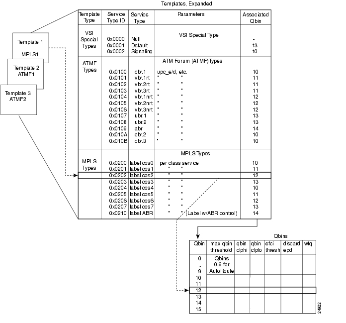
Each template table row includes an entry that defines the qbin to be used for that class of service. See for an illustration of how service class databases map to qbins. This mapping defines a relationship between the template and the interface qbin's configuration.
A qbin template defines a default configuration for the set of qbins for the logical interface. When a template assignment is made to an interface, the corresponding default qbin configuration becomes the interface's qbin configuration. Some of the parameters of the interface's qbin configuration can be changed on a per interface basis. Such changes affect only that interface's qbin configuration and no others, and do not affect the qbin templates.
Figure 17-9 Service Template Overview
Qbin templates only are used with qbins that are available to VSI partitions, namely qbins 10 through 15. Qbins 10 through 15 are used by the VSI on interfaces configured as trunks or ports. The rest of the qbins (0-9) are reserved for and configured by Automatic Routing Management.
Each template table row includes an entry that defines the qbin to be used for that class of service. This mapping defines a relationship between the template and the interface qbin's configuration. As a result, you need to define a default qbin configuration to be associated with the template.
Note
Figure 17-10
Service Template and Associated Qbin Selection
Extended Service Types Support
The service-type parameter for a connection is specified in the connection bandwidth information parameter group. The service-type and service-category parameters determine the service class to be used from the service template.
Supported Service Categories
There are five major service categories and several sub-categories. The major service categories are shown in . A list of the supported service sub-categories is shown in LCNs.
Table 17-6 Service Category Listing
CBR
0x0100
VBR-RT
0x0101
VBR-NRT
0x0102
UBR
0x0103
ABR
0x0104
Supported Service Types
The service type identifier is a 32-bit number. The service type identifier appears on the dspsct screen when you specify a service class template number and service type; for example:
dspsct <2> <vbrrt1>
A list of supported service templates and associated qbins, and service types is shown in .
Qbin Default Settings
The qbin default settings are shown in . The Service Class Template default settings for Label Switch Controllers and PNNI controllers are shown in .
Note: Templates 2, 4, 6, and 8 support policing on PPD.
Configuring the Virtual Switch Interface
In the VSI control model, a controller sees the switch as a collection of slaves with their interfaces and it can establish connections between any two interfaces. The controller uses resources allocated to its partition. You can continue to configure VSI resources on a given interface by using the cnfrsrc command. You attach a controller to a node to control the node by using the addshelf command.
You can assign each VSI interface a default class of service template when you activate it. You can use the switch software CLI or Cisco WAN Manager to configure a different template to an interface.
VSI Commands
addctrlr: Use this command to enable the VSI capabilities on the trunk interface. New in this release.
cnfrsrc: Use this command to configure resource on the trunk interface for the PNNI controller's control channels.
cnfvsiif: Use this command to assign a template number to an active interface.
cnfvsipart: Use this command to configure VSI partition characteristics. New in this release.
delctrlr: Use this command to disable VSI capabilities on the trunk interface. New in this release.
dspchuse: Use this command to display a summary of the channel distribution in a given slot. New in this release.
dspctrlrs: Use this command to display all VSI controllers attached to the BPX. These controllers could be either a PNNI controller or an MPLS controller. New in this release.
dspvsiif: Use this command to display the template number assigned to an interface.
dspsct: Use this command to display the service class template. It has three levels of operation:
•
•
•
dspqbint: Use this command to display the Qbin templates.
dspvsipartinfo: Use this command to display VSI resource status information for the partition.
dspvsipartcnf: Use this command to display VSI partition characteristics. New in this release.
cnfqbin: Use this command to configure the Qbin parameters. Use this command to change accept the interface template as the values, as an option. For example, you can enter "Yes" when prompted whether the interface service class template should be used, and the command will use the card's qbin values from the qbin templates. You will not be able to enter desired values for any qbin parameter in this case. You can, however, enter desired values when the template option is not chosen.
dspqbin: Use this command to display the Qbin parameters currently configured for an interface. The dspqbin command shows whether the Qbin has been configured by a user OR by a template.
dspcmi: This is a debug command, which displays the current capabilities reported by the firmware on the card.
dspcd: This command displays the characteristics of the card. Changes will be made to reflect the current VSI version supported by the card.
Table 17-10
Maximum PVC Bandwidth for all Partitions on Logical Interface
VSI Related Parameters and Descriptions
These tables provide parameters related to VSI configuration and some descriptions. In most cases, the object name is similar or identical to the screen field name as it appears on the CLI (for various VSI commands such as cnfrsrc, cnfvsiif, dspsctmplt, and so on.)
Troubleshooting VSI Problems
This section describes how different types of channels are allocated (VSI, Automatic Routing Management), and how to troubleshooting some problems related to VSI. Note that some or all of the commands discussed in this section require service-level or above user privileges. To access these commands, you must have debug (Service or StrataCom level) privileges and passwords. Check with the TAC for assistance.
How Channels are Allocated and Deallocated
To understand channel allocation and deallocations problems, it's important to understand how the channels are distributed. The BXM card can support x number of channels. The value x varies between different models of BXMs.
How Networking Channels are Allocated
Networking channels are assigned for trunk interfaces only. This includes physical, feeder, and virtual. Every physical and feeder trunk that is active is assigned 271 networking channels. For virtual trunks, the first virtual trunk upped on a port is assigned 271 networking channels. Every subsequent one requires an additional one. So if the second virtual trunk on the same port is upped, one more networking channel is reserved for that virtual trunk.
How Automatic Routing Management Channels are Allocated/Configured
When a port or trunk interface is upped, a default value of 256 PVC channels are assigned. You can use the cnfrsrc command to change this value to fit your needs. Note that this is only the number of PVC channels configured. Every time a connection is added on the port or trunk interface, a counter is incremented to keep count of the number of PVCs used. This counter can never exceed the number configured. For the trunk interface, connections will be rerouted if the new value configured is less than the old value. For the port interface, cnfrsrc will not allow you to decrease the configured value to be less than the used value. You will need to delete connections before decreasing the PVC value.
How SVC Channels are Allocated and Configured
You can configure the number of SVC channels by using the cnftrk or the cnfport command. SVC and VSI channels cannot co-exist. The command will block you from configuring channels if there are VSI channels allocated.
How VSI Channels are Assigned for VSI Master to Slave VCs
When a VSI shelf is added with the addshelf command on the feeder interface, 12 LCNs are reserved for master to slave VCs. The reason for 12 LCNs is that one LCN is needed to communicate to an active BXM (with VSI functionality). The BPX has 15 slots possible, two of which are used for the BCC and one used for the ASM card. The worse case is if the BPX has all BXM cards in the node, therefore the master endpoint (that is, the card with the VSI shelf added) needs 12 LCNs to communicate with all the cards on the node. The command dspvsich will display all the LCNs reserved for master to slave VCs and interslave VCs.
How VSI Channels Are Configured/Allocated
VSI channels are configured through the cnfrsrc command. The user specifies a vsi min and a vsi max for the partition. The number of channels that is allocated is max (sum_of_min, max_of_max).
For example:
port group 1:
port 1: min max
partition 1: 1000 1000
port 2:
partition 1: 2000 1000
port group 2:
port 3:
partition 1: 2000 5000
port 4:
partition 1: 2000 4000
For portgroup 1:
sum_of_min = 3000; max_of_max = 1000
For portgroup 2:
sum_of_min = 4000; max_of_max = 5000
Therefore, the number of channels allocated for VSI is 8000.
How Background Redundancy Channels are Allocated
The formula for getting the LCN is num_chans + 1. These channels are used for y-redundancy cards to communicate with each other.
How IP Channels are Allocated
IP channels are used for ALL5 messaging. The LCNs are reserved within switch software. The formula for getting the LCN is num_chans + 14 + port (0 based). Twelve (12) LCNs are reserved for IP channels, one for each port.
How ILMI/LMI Channels are Allocated
The formula for getting the LCN is num_chans + 2 + port.
How ILMI Channels are Allocated for VSI Partitions on Trunk Interfaces
When ILMI functionality is enabled for a VSI partition on a trunk interface, a new ILMI session is started on the BXM card for the trunk interface. The LCN for this session is allocated from the LCNs available for the AutoRoute partition. This LCN is allocated from the port-based pool; not from the card-based pool.
Note that no new LCN is allocated when ILMI functionality is enabled for VSI partitions on port interfaces. This is because the ILMI functionality for VSI partitions on port interfaces use the same ILMI functionality that is started for AutoRoute. These use the pre-allocated LCN as discussed in the preceding section.
How VSI Channels are Assigned for Interslave VCs
Interslave vcs are assigned with LCNs that are reserved within switch software. These lcns are not taken from the pool. The formula for getting the lcn is num_chans + 26 + dest_slot where num_chans is the number of channels the card supports
mc_vsi_end_lcn
This value is shown in the dsplogcd command. If the value is 0, then there are no vsi channels configured on the card. If it is not zero, then there are VSI channels. It marks the first VSI channel.
num chans
This value is shown in the dsplogcd command as "Physical Chans". It is reported to switch software from the card. Each BXM will vary in the number of channels that it supports.
How Port Group Enters the Channel Assignment Picture
Note
There are some models of BXM cards which will support more than 1 port group. The command dsplogcd and dspcd will indicate the number of port groups supported. Even though each card supports x channels, there is a hardware limitation of how many channels can be supported between certain ports. A set of ports are grouped into port groups; that is, a BXM 8-port OC-3 card has two port groups, consisting of ports 1-4, and 5-8 respectively. Each port group will have an upper limit of the number of channels it can support, majority of the time it's
(num_chans / num_of_port_groups).
cnfrsrc fails with "available channels is 0"
Description of Problem
When the user thinks that there are channels available, but cnfrsrc says that the number of available channels is 0. The user will not be able to allocate any more vsi channels.
Initial Investigations
This may not be a problem, since the user may not have accounted for hidden channel assignments like networking and VSI vcs. Execute the dspchuse command to see where all the channels are allocated. Note any channel assignment that looks suspicious. Verify this page with the channels configured from the cnftrk and cnfrsrc command.
The dspchuse command is available to users in this release.
Workarounds
The work around depends on where the problem is. If it's with PVCs, try cnfrsrc and change the number of pvcs. Since switchcc, will rebuild the channel database, try executing switchcc.
Detailed Debugging
You should perform the following tasks:
•
•
•
•
2 vsi shelf added
•
1 vsi shelf added
•
Two (2) trunks are upped
One (1) port is upped
•
•
•
Verify if anyone has disable a partition.
Disabling the partition will not recalculate the end_lcn value. The end_lcn will be recalculated by a card reset or a switchcc command or a node rebuild.
cnfrsrc fails with "Automatic Routing Management is currently using the channel space"
Description of Problem
This error is indicating that there are Automatic Routing Management channels currently configured on the space that the user wants for VSI.
For example: Let's say the BXM card supports 100 channels. Currently 50 of the channels are configured for PVCs and 50 for VSI ranging from 51-100. Let's suppose that the card has 5 connections on channel 45-49. Now change the configuration of PVCs to 10. The command will work since only five (5) are currently used. The available channels on the card is now 40. If cnfrsrc is executed now to increase the number of VSI channels, the command will fail, because channels 45-49 are currently in use.
Initial Investigations
•
•
•
•
•
•
•
Workarounds
The only work around is to somehow delete the connections currently using the high end of the channel range. On the trunk interface, causing the connections to reroute will likely cause the lower lcn range to be used first. On the port interface, deleting and re-adding the connection.
Detailed Debugging
Refer to the section "Initial Investigations" section.
Summary of Commands
shows the command name and starting page for the description of each VSI-related command.
addctrlr
Adds VSI capabilities to a trunk interface to which a feeder of type AAL5 is attached. The addctrlr command is used only to connect a Private Network to Network Interface (PNNI) controller. PNNI controller software resides on the SES hardware.
The addctrlr command is the second step in the adding of a PNNI controller to a BPX node.
The first step is to run the command addshelf with shelf type set to X to add a AAL5 feeder. This ensures that Annex G protocol runs between the BPX and the SES.
Then run the addctrlr command to set up the VSI control channels from the PNNI SES controller to the VSI slave processes running on the BXM cards to ensure full VSI functionality for the PNNI controller. You execute the addctrlr command on an existing AAL5 interface shelf.
Also note that you can add a PNNI controller to a Trunk interface only if the interface already has an active VSI partition corresponding to the partition that is controlled by the PNNI controller. Suppose a PNNI controller controlling the partition 1 were added to an trunk interface 12.1. Then it would be necessary that a VSI partition corresponding to partition 1 be active on the interface 12.1. Otherwise the addctrlr command would fail.
When you add VSI controller capabilities onto an AAL5 interface shelf (or feeder), the switch software prompts you for the specifics of the VSI controller:
•
•
•
•
There could be 12 BXM cards on the BPX node and the PNNI controller would control VSI partitions on those BXM cards that support VSI capability. Hence a separate VSI control channel must be set up from the PNNI control to each BXM card that supports VSI. Suppose you specify a VPI value of 0 and start VCI value of 40 for the VSI control channels. Then the control channel corresponding to any BXM card on slot 1 would use VPI, VCI values <0, 40>. The VSI control channels to other slots would use the VPI, VCI values of <0, 40+slot-1>, where "slot" corresponds to the slot number of the BXM card.
Note
Caution
The addition of a controller to a node will fail if there are not enough channels available to set up the control VCs in one or more of the BXM slaves.
Full Name
Add VSI capabilities to a AAL5 feeder interface.
Syntax
addctrlr < slot.port> <controller id> <partition id> <control_vpi> <start_vci>
Related Commands
addshelf, delctrlr, dspctrlrs
Attributes
Example 1
addctrlr 10.4 3 2 0 40
Description
Add controller to port 4 on slot 10,, partition ID of 2, and controller ID of 3.
System Response
night TN StrataCom BPX 8600 9.2.00 Apr. 11 1998 14:31 GMTBPX Controllers InformationTrunk Name Type Part Id Ctrl ID Ctrl IP State10.3 PNNI VSI 1 1 192.0.0.0 Enabled11.1 VSI VSI 2 2 192.0.0.0 DisabledWarning partition already in use do you want to add redundant controllerLast Command: addctrlr 10.4 3 2 0 40Next Command:Description
Adds a controller, such a PNNI controller, to a BPX interface shelf.
System Response
night TN StrataCom BPX 8600 9.2.00 Apr. 11 1998 14:31 GMTBPX Controllers InformationTrunk Name Type Part Id Ctrl ID Ctrl IP State10.3 PNNI VSI 1 1 192.0.0.0 Enabled11.1 VSI VSI 2 2 192.0.0.0 DisabledWarning partition already in use do you want to add redundant controllerLast Command: addctrlr 10.3 3 1 0 40Next Command:addshelf
Adds an ATM link between a hub node and an interface shelf such as an MGX 8220. an MGX 8850, or IGX shelf in a tiered network; or an ATM link between a BXM card on a BPX node and a MPLS (Multiprotocol Label Switching) controller such as a series 7200 or 7500 router; or an ATM link between a BXM card on a BPX node and an Extended Services Processor. (An MPLS Controller or an Extended Services Processor is considered an interface shelf from the BPX switch's perspective.) The routing hub can be either a BPX or an IGX.
The interface shelf can be one of the following:
•
•
•
•
•
•
The signaling protocol that applies to the trunk on an interface shelf is Annex G. For example, in this release, the IGX 8400 interface shelf with a BTM E1 interface communicates with the routing hub through the Annex G LMI using STI cell format. However, the MGX 8850 interface shelf, or feeder, communicates over a UXM/UXM-E interface with the routing hub over Annex G LMI using AAL5 format.
Note
Each IGX/AF, MGX 8220, or MGX 8850 shelf has one trunk that connects to the BPX or IGX node serving as an access hub. A BPX routing hub can support up to 16 T3 trunks to the interface shelves, which can be IGX/AF, MGX 8220, or MGX 8850 interface shelves. An IGX hub can support up to four trunks to the interface shelves, which can be IGX/AF shelves only.
An IGX 8400 interface shelf can connect to an IGX 8400 routing hub over a BTM E1 interface using STI cell format. In Release 9.1, an IGX 8400 interface shelf can connect to an MGX 8800 over a UXM/UXM-E interface using ATM cell format.
Before it can carry traffic, you must "up" trunk on an interface shelf (using uptrk) on both the interface shelf and the hub node and "add" it to the network (using addshelf). Also, a trunk must be free of major alarms before you can add it with the addshelf command.
In this release, the new parameters "Control VPI" and "Control VCI start" have been added.
In this release, addshelf will prevent adding a feeder to a trunk if a VSI ILMI session is active on a VSI partition on the trunk interface.
Adding a VSI Controller
The maximum number of controllers that can be attached to a given node is limited by the maximum number of feeders (16) that can be attached to a BPX hub. Therefore the total number of feeders and controllers cannot exceed 16.
You add a VSI controller, such as an MPLS (Multiprotocol Label Switching) Controller, to a switch with the addshelf command using the vsi option. The vsi option of the addshelf command is used to identify VSI controllers and tell them apart from interface shelves (feeders). The VSI controllers are allocated a partition of the switch resources. VSI controllers manage their partition through the VSI interface. The controllers run the VSI master. The VSI master entity interacts with the VSI slave running on the BXMs through the VSI interface, to set up VSI connections using the resources in the partition assigned to the controller. Two controllers that are intended to be used in a redundant configuration must specify the same partition when added to the node through the addshelf command.
When a controller is added to the node switch software will set up the infrastructure so that the controllers can communicate with the slaves in the node. The VSI entities decide how and when to use these communication channels.
In addition, the controllers require a communication channel between them. This channel could be in-band or out-of-band. When a controller is added to the switch, switch software will send controller information to the slaves. This information will be advertised to all the controllers in the partition. The controllers may decide to use this information to set up an intermaster channel. Alternatively the controllers may use an out-of-band channel to communicate.
The maximum number of controllers that can be attached to a given node is limited by the maximum number of interface shelves (feeders) that can be attached to a BPX hub. This number in Release 9.2 is 16. Therefore the total number of feeders and controllers cannot exceed 16.
To add a controller to the node, use the addshelf command. A redundant controller is added in the normal way, except that it specifies a partition that may be already in use by another controller. In this release, the addshelf command allows for up to two controllers to manage the same partition.
One of the parameters that must be specified with the addshelf command when a VSI controller is added to the switch is the controller id. This is a number between 1 and 32 that uniquely identifies the controller. Two different controllers must always have different controllers id.
The management of resources on the VSI slaves requires that each slave in the node has a communication control VC to each of the controllers attached to the node. When a controller is added to the BCC via the addshelf command, the BCC sets up the set of master-slave connections between the new controller port and each of the active slaves in the switch. The connections are set up using a well known vpi.vci. The value of the vpi is 0. The value of the vci is (40 + (slot - 1)) where slot is the logical slot number of the slave.
Feature Mismatching to Verify VSI Support
The cnfrsrc and addshelf commands, in addition to other configuration commands, will perform mismatch verification on the BXM and UXM cards. For example, the cnfrsrc and addshelf commands will verify whether the cards both have VSI 2.0 support configured. Refer to "Feature Mismatching" section on page 18-1 for more information on Feature Mismatching in Release 9.2.
The Feature Mismatching capability will not mismatch cards unless the actual feature has been enabled on the card. This allows for a graceful card migration from an older release.
Full Name
Add an interface shelf (feeder) or a controller to a routing node or hub.
Syntax
Interface shelf:
addshelf <slot.port> <shelf-type> <vpi> <vci>
MPLS (Multiprotocol Label Switching) controller:
addshelf <trunk slot.port> v <ctrlr id> <part id> <control vpi> <control vci start> <redundant ctrlr warning>
Note
Related Commands
addctrlr, delshelf, dspnode, dsptrks
Attributes
Example 1
Interface shelf: addshelf 11.1 a 21 200
MPLS (Multiprotocol Label Switching) controller: addshelf 4.1 vsi 1 1
Description
Interface shelf:
Add trunk 11.1 as an MGX 8220 interface shelf. After you add the shelf, the screen displays a confirmation message and the name of the shelf.
MPLS (Multiprotocol Label Switching) controller:
Add trunk 4.1 as a VSI-MPLS (Multiprotocol Label Switching) Controller interface shelf. After you add the LSC, the screen displays a confirmation message and the name of the shelf.
Description for Interface Shelves
An interface shelf can be one of the following:
•
•
•
•
The (VPI.VCI) of the 15 control VCs is:
(control_VPI.control_VCI_start) to (control_VPI.control_VCI_start+14).The control VC used for slot n (1<= n<=15) is:
(control_VPI.control_VCI_start + n -1).Example for Interface Shelves
Add an MGX 8220 at trunk 11.1 After you add the shelf, the screen displays a confirmation message and the name of the shelf. Add the MGX 8220 (may be referred to on screen as AXIS) as follows:
addshelf 11.1 a
The sample display shows a partially executed command prompting you for the interface shelf type:
System Response
nmsbpx23 TN SuperUser BPX 8620 9.2 Apr. 4 1998 13:28 PSTBPX Interface Shelf InformationTrunk Name Type Alarm1.3 AXIS240 AXIS OK11.2 A242 AXIS OKThis Command: addshelf 11.1Enter Interface Shelf Type: I (IGX/AF), A (AXIS), P (APS), V (VSI), X (AAL5)Next Command:Example for Adding an MGX 8850 AAL5 (ATM Adaptive Layer/5) Interface Shelf
Add an MGX 8850 at trunk 4.8. After you add the MGX 8800 shelf, the screen displays a confirmation message and the name of the shelf. Add the MGX 8850 (may be referred to on screen as AAL5) as follows:
addshelf 4.8 x
The sample display shows that an MGX 8850 was added on trunk 4.8 as an AAL5 (ATM Adaptive Layer/5 type of interface shelf. (Adding an MGX 8850 interface shelf is similar to adding a MPLS (Multiprotocol Label Switching) Controller interface shelf.)
System Response
pswbpx3 TN SuperUser BPX 8600 9.1 June 6 1998 13:28 PSTBPX Interface Shelf InformationTrunk Name Type Part Id Ctrl Id Alarm4.8 SIMFDR0 AAL5 - - OKThis Command: addshelf 4.8 xEnter Interface Shelf Type: I (IGX/AF), A (AXIS), P (APS), V (VSI), X (AAL5)Next Command:Description for MPLS
For MPLS, before it can carry traffic, you need to "up" the link to a MPLS controller (by using either uptrk or upport) at the BPX node. You can then add the link to the network (by using addshelf). Also, the link must be free of major alarms before you can add it with the addshelf command.
Note
Table 17-14 MPLS Parameters-addshelf
Example for MPLS
Add a MPLS controller link to a BPX node by entering the addshelf command at the desired BXM port as follows:
addshelf 4.1 vsi 1 1
System Response
nmsbpx23 TN SuperUser BPX 15 9.1 Apr. 4 1998 13:28 PSTBPX Interface Shelf InformationTrunk Name Type Alarm5.1 j6c AXIS MIN5.3 j5c /AF MIN4.1 VSI VSI OKThis Command: addshelf 4.1 v 1 1Next Command:Example for VSI Controller
Add a VSI controller link to a BPX node by entering the addshelf command at the desired BXM port as follows:
addshelf 13.2
System Response
sw237 TN StrataCom BPX 8620 9.2.L3 May 10 1999 14:48 PSTTRK Type Current Line Alarm Status Other End4.1 [T3 Clear - OK VSI(VSI)10.1 OC-3 Clear - OK VSI(VSI)10.5 OC-3 Clear - OK VSI(VSI)13.1.1 OC-3 Clear - OK -13.2 OC-3 Clear - OK -This Command: addshelf 13.2addyred
Enables card redundancy for IGX and BPX cards. Use the addyred command to specify the slots of the primary and secondary (standby) cards that form the redundant pair. Refer to the "Specifying Card Redundancy" section on page 3-3" section at the beginning of this chapter for a list of supported card sets.
You must use the addyred command to configure a VSI slave redundant card. When a standby slave card is first started (either by having been inserted into the slot, or if the user issues the addyred command from the CLI console), the active slave VSI forwards all VSI messages it had received from the Master VSI controller card to the standby slave VSI controller card.
Redundant card sets must have the following characteristics:
•
•
•
•
•
In both the single and multiport card sets, if the secondary card set becomes active, the primary card set serves as its backup (assuming the primary card set is complete and not failed). You cannot use the addyred command if the primary and secondary slots are empty. If cards reside in the primary and secondary slots, the system checks for card compatibility. Two types of incompatibility can occur: back card and jumper or cable inconsistencies. (On SDI, FRI, and FTI cards, jumpers determine whether a port is configured as DCE or DTE. On LDI cards, either a DCE or DTE adapter cable connects to the LDI port. For descriptions of the jumper positions and cabling, see the Cisco IGX 8400 Series Installation and Configuration manual.)
Note that the addyred command prevents invalid configurations when you try to configure the SONET APS feature. When SONET Automatic Protection Switching (APS) is configured, you will not be able to use the addyred or delyred commands on a card configured for APS 1:1 architecture. That is, you will not be able to execute the addyred command, then configure the APS 1:1 architecture. Similarly, you will not be able to configure APS 1:1, then execute the addyred command. You will be blocked from executing these commands at the command line interface.
If incompatibilities exist, the message "Y-Cable Conflict" appears on the screen. Specific conflicts are listed in reverse video in the dspyred display. See the dspyred description for more information.
To ensure that only cards with the Idle Code Suppression feature enabled on them are allowed to be a Y-redundancy pair, addyred blocks cards that have different idle code suppression capability.
Full Name
Add Y-cable redundancy.
Syntax
addyred <primary slot> <secondary slot>
Related Commands
delyred, dspyred, prtyred
Attributes
Example 1
addyred 25 26
Description
Add Y-cable redundancy to the SDP/SDI card sets in slots 25 and 26.
System Response
beta TRM YourID:1 IGX 8420 9.2 Aug. 15 1998 14:27 MSTSlot Other Front Back Channel ConfigurationSlot Type Slot Card Card 1 2 3 4 5 6 7 82 Pri 3 BXM LM-BXM3 Sec 2 BXM LM-BXMLast Command: addcdred 2 3Next Command:Table 17-15 baddyred-Parameters
primary slot
Specifies the slot number of the primary card set.
secondary slot
Specifies the slot number of the secondary card set.
cnfqbin
Use the cnfqbin command to configure the qbin (Class of Service Buffers parameters on a selected BXM port or trunk. The cnfqbin command prompts you to configure the qbin from the template assigned to a logical interface.
This command now lets you accept the interface template as the values, as an option. For example, you can type in "Yes" when prompted whether the interface SCT (service class template) should be used, and the command will use the card qbin values from the qbin templates. You will not be allowed to enter values for any qbin parameter in this case. You can, however, enter desired values if the "template" option has not been chosen.
When you activate an interface (VI) with uptrk or upport, the default service template is assigned to the interface (VI). The corresponding qbin template is then copied into the card's (BXM) data structure of that interface. You can change some of the qbin parameters by using the cnfqbin command. The qbin is now "user configured" as opposed to "template configured." You can view information on the dspqbin screen.
When a VSI interface is activated, the default template gets assigned to an interface. The corresponding qbin template gets copied into the card qbin data structure for that interface. When you want to change this, by giving new values using the cnfqbin command, the qbin is now "user configured" as opposed to "template configured." This information is displayed on the dspqbin screen. It indicates whether the values in the qbin are from the template assigned to the interface OR the values have been changed to user-defined values.
The cnfqbin command was introduced in Release 9.1 to configure any Qbin on the BXM cards. In this release, it has been extended to support virtual trunks. When the virtual trunk is dedicated to the controller, you can only configure qbin 10-15.
The cnfqbin command will prompt you whether "template" should be used for Qbin parameters. In this release, the dspqbin command now displays all the fields of a qbin template. It also indicates whether the qbin is "user configured" or "template configured."
VC connections are grouped into large buffers called qbins. (Per-VC queues can be specified on a connection-by connection basis also). In this release, all VSI connections use qbin 10 on each interface.
You configure Multiprotocol Label Switching (formerly Tag Switching) for VSIs on a BXM card is configured using the cnfrsrc and cnfqbin commands. Qbin 10 is assigned to tag switching.
Use the cnfqbin command is used to adjust the threshold for the traffic arriving in Qbin 10 of a given VSI interface as away of fine tuning traffic delay.
If you use the cnfqbin command to set an existing qbin to disabled, the egress of the connection traffic to the network is disabled. Re-enabling the qbin restores the egress traffic.
Note
CTD (Cell Tolerance Delay), which is the fixed delay, is based on a fixed value, and is not configurable.
The cnfqbin command prompts you whether "template" should be used for qbin parameters.
Full Name
Configure qbin
Syntax
cnfqbin <slot number>.<port number>.<vtrk>
Related Commands
dspqbin
Attributes
Example 1
cnfqbin 13.1
Description
Create a qbin configuration on the OC-3 trunk on port 1 of slot 13 on the BPX to support MPLS (Multiprotocol Label Switching).
System Response
sw57 TN SuperUser BPX 8600 9.2 Mar. 10 1997 10:41 GMTPort/Trunk: 13.1 [ACTIVE ]Qbin Id :Enable Qbin (Y/N) :Minimum Bandwidth :Qbin Discard threshold:Low CLP threshold: [80] %High CLP threshold: [80] %EFCI threshold: [30]%Last Command: cnfqbin 13.1Example 2
cnfqbin 4.1 10
Description
Configure the Qbin 10 for port 4.1; also configure ports 4.2 and 4.3, and enter port 4.2 and 4.3 where applicable.
If the qbin is not configured, configure the queues on the ports using the cnfqbin command:
cnfqbin 4.1 10
enable/disable: e
For all other parameters, accept the (default).
The previous parameters can also be set for qbin 10 as follows:
cnfqbin 4.1 10 e 0 65536 95 100 40
System Response
Sample Display:n4 TN SuperUser BPX 15 9.2 Apr. 4 1998 16:41 PSTQbin Database 4.1 on BXM qbin 10Qbin State: EnabledMinimum Bandwith: 0Qbin Discard threshold: 65536Low CLP/EPD threshold: 95%High CLP/EPD threshold: 100%EFCI threshold: 40%This Command: cnfqbin 4.1 10'E' to Enable, 'D' to Disable [E]:Next Command:System Response
n4 TN SuperUser BPX 8620 9.2 Apr. 4 1998 16:41 PSTQbin Database 4.1 on BXM qbin 10Qbin State: EnabledMinimum Bandwith: 0Qbin Discard threshold: 65536Low CLP/EPD threshold: 95%High CLP/EPD threshold: 100%EFCI threshold: 40%Last Command: cnfqbin 4.1 10 e 0 65536 95 100 40Next Command:
Qbin Dependencies
The available qbin parameters are shown in . Notice that the qbins available for VSI are restricted to qbins 10-15 for that interface. All 32 possible virtual interfaces are provided with 16 qbins.
Table 17-17
cnfqbin Parameters
cnfrsrc
Use the cnfrsrc command to partition resources for Automatic Routing Management PVCs or VSI-MPLS (Multiprotocol Label Switching).
This command was introduced in Release 9.1 to support physical trunks. It has been extended to support virtual trunks. After VSI has been enabled, the virtual trunk becomes a "dedicated" VSI virtual trunk. Note that if the trunk has already been added or if the VPI value has not been configured, you will not be able to configure the VPI value. (Switch software will block you from doing so.)
You can configure a virtual trunk to be dedicated to VSI or to Automatic Routing Management. You cannot configure a virtual trunk for both VSI and Automatic Routing Management.
The switch software:
•
•
•
Configurable resources (using cnfrsrc) are:
•
•
•
•
•
•
•
•
•
•
•
•
Resource Partitioning
The VSIs need to partition the resources between competing controllers: Automatic Routing Management, MPLS (Multiprotocol Label Switching), and PNNI for example. You can have different types of controllers splitting up a partition's assets. For example, Automatic Routing Management, and MPLS, or Automatic Routing Management and PNNI (SVCs), but not PNNI and MPLS.
This release supports one or two partitions only. In this release, two controllers of a single type are supported. The user interface will block the activation of partitions with ID higher than 1 if the card does not support multiple partitions.
When enabling a partition, If [start_VPI, end_VPI] of the partition contains any "reserved" VPI, an error message is displayed and you are prompted for different values for start_VPI, end_VPI. Thus, if VPI 10 is used for control VCs on an interface, then you cannot include VPI 10 in any VSI partition by using the cnfrsrc command. An error message would be displayed.
The resources that you need to configure for a partition are shown in for a partition designated ifci, which stands for interface controller 1, in this example. The three parameters that need to be distributed are: 1) number of logical connections (lcns); 2) bandwidth (bw); and 3) virtual path identifiers (vpi).
Table 17-18 ifci parameters (virtual switch interface)
lcns
min_lcnsi
max_lcnsi
bw
min_bwi
max_bwi
vpi
min_vpi
max_vpi
The controller is supplied with a logical LCN connection number, that is slot, port, and so on., information that is converted to a logical connection number (lcn).
Some ranges of values available for a partition are listed in :
When you add a trunk, the entire bandwidth is allocated to Automatic Routing Management (formerly Automatic Routing Management). To change the allocation to provide resources for a VSI, use the cnfrsrc command on the BPX switch. A view of the resource partitioning available is shown in .
Figure 17-11 Graphical View of resource partitioning, Automatic Routing Management and vsi
Partition Information Sent to Cisco WAN Manager
When the partition information is configured for the first time or any parameters are changed, Cisco WAN Manager will be updated through a robust message.
•
This field represents the minimum guaranteed channels available for a given port•
This field represents the maximum number of channels available, but not guaranteed, for a port.•
This field represents the starting VPI that can be used by VSI.•
This field represents the end of the VPI range that can be used by VSI.•
This field represents the minimum guaranteed bandwidth available for a port.•
This field represents the maximum bandwidth available, but not guaranteed, for a port.Partitioning
On each interface (port or trunk) on the BXM cards used for label switching, two sets of resources must be divided up between traditional PVC connections and tag switching connections. The traditional PVC connections are configured directly on the BPX platform, and tag switching connections are set up by the TSC using the VSI. The following resources are partitioned on each interface:
•
•
As with all ATM switches, the BPX switch supports up to a specified number of connections. On the BPX switch, the number of connections supported depends on the number of port/trunk cards installed. On each interface, space for connections is divided up between traditional BPX switch permanent virtual circuit (PVC) connections, and Label Switching VCs (LVCs).
cnfrsrc Parameters, Possible Values, and Descriptions
See for a listing of cnfrsrc parameters, ranges and values, and descriptions. These parameters appear on the cnfrsrc screen.
Feature Mismatching to Verify VSI Support
In this release, the cnfrsrc and addshelf commands, in addition to other configuration commands, performs mismatch verification on the BXM and UXM cards. For example, the cnfrsrc and addshelf commands will verify whether the cards both have VSI 2.0 support configured. Refer to "Feature Mismatching" section on page 18-1 for more information on Feature Mismatching in Release 9.2.
The Feature Mismatching capability will not mismatch cards unless the actual feature has been enabled on the card. This allows for a graceful card migration from an older release.
Full Name
Configure resources
Syntax
cnfrsrc <slot.port.vtrk>
or
cnfrsrc <slot>.<port>.<vtrk> <maxpvclcns> <maxpvcbw> <partition> <e/d> <minvsilcns> <maxvsilcns> <vsistartvpi> <vsiendvpi><vsiminbw> <vsimaxbw>
Related Commands
dsprsrc
Attributes
Example 1
cnfrsrc 4.1 256 26000 1 e 512 16384 2 15 26000 100000
Description
Configure the VSI partition for port 4.1.
System Response
n4 TN SuperUser BPX 8620 9.2 Apr. 4 1998 16:40 PSTPort/Trunk : 4.1Maximum PVC LCNS: 256 Maximum PVC Bandwidth:26000Min Lcn(1) : 0 Min Lcn(2) : 0Partition 1Partition State : EnabledMinimum VSI LCNS: 512Maximum VSI LCNS: 7048Start VSI VPI: 2End VSI VPI : 15Minimum VSI Bandwidth : 26000 Maximum VSI Bandwidth : 100000Last Command: cnfrsrc 4.1 256 26000 1 e 512 7048 2 15 26000 100000Next Command:Example 2
cnfrsrc 13.1
Description
Partition resources on the OC-3 trunk on port 1 of slot 13 on the BPX to support a service such as VSI-MPLS (or PNNI SVCs).
System Response
n4 TN SuperUser BPX 8620 9.2 Apr. 4 1998 16:40 PSTPort/Trunk : 4.1Maximum PVC LCNS: 256 Maximum PVC Bandwidth:26000Min Lcn(1) : 0 Min Lcn(2) : 0Partition 1Partition State : EnabledMinimum VSI LCNS: 512Maximum VSI LCNS: 7048Start VSI VPI: 2End VSI VPI : 15Minimum VSI Bandwidth : 26000 Maximum VSI Bandwidth : 100000Last Command: cnfrsrc 4.1 256 26000 1 e 512 7048 2 15 26000 100000Next Command:Example 3
cnfrsrc 4.1
Description
Port 4.1 is the slave interface to the label switch controller. Configure the VSI partitions for port 4.1 as follows:
cnfrsrc 4.1
PVC LCNs: [256] {accept default value}
max PVC bandwidth: 26000
partition: 1
enabled: e
VSI min LCNs: 512
VSI max LCNs: 7048 {varies with BXM type
VSI start VPI: 2
VSI end VPI: 15
VSI min b/w: 26000
VSI max b/w: 100000
or with one entry as follows:
cnfrsrc 4.1 256 26000 1 e 512 7048 2 15 26000 100000
System Response
n4 TN SuperUser BPX 15 9.2 Apr. 4 1998 16:40 PSTPort/Trunk : 4.1Maximum PVC LCNS: 256 Maximum PVC Bandwidth:26000Min Lcn(1) : 0 Min Lcn(2) : 0Partition 1Partition State : EnabledMinimum VSI LCNS: 512Maximum VSI LCNS: 7048Start VSI VPI: 2End VSI VPI : 15Minimum VSI Bandwidth : 26000 Maximum VSI Bandwidth : 100000Last Command: cnfrsrc 4.1 256 26000 1 e 512 7048 2 15 26000 100000Next Command:
Note
Note
Note
Note
lists the cnfrsrc parameters, focusing more on configuring resources for VSI partitions (an MPLS controller, for example). For more information on configuring resources for Automatic Routing Management PVCs, refer to the cnfrsrc command in Chapter 4, "Setting Up Trunks" and Chapter 5, "Setting Up Lines."
cnfvsiif
You can use the dspvsiif command to display a service class template assigned to an interface (VI). You can also display a summary of the resources allocated to the VSI partition on a given interface. Multiple users are allowed to use the dspvsiif at one time.
Assigning a Service Template to an Interface
A default service template is assigned to a logical interface (VI) when you up the interface by using upport/uptrk.
For example:
•
•
•
This default template has the identifier of 1. You can change the service template from service template 1 to another service template using the cnfvsiif command. The dspvsiif command allows you to display the template associated with the interface. For example:
•
•
•
•
cnfvsiif example
You use the cnfvsiif command to assign a selected service template to an interface (VI) by specifying the template number. It has the following syntax:
cnfvsiif <slot.port.vtrk> <tmplt_id>
Full Name
Configure a service class template and assign it to an interface
Syntax
cnfvsiif <slot.port.vtrk> <tmplt_id>
Related Commands
cnfrsrc, dsprsrc, cnfqbin, dspqbin
Attributes
Example 1
cnfvsiif 11.1 2
System Response
sw53 TN StrataCom BPX 8600 9.2.a5 Date/Time Not SetPort: 11.1Service Class Template ID: 2Last Command: cnfvsiif 11.1 2Next Command:cnfvsipart
Use this command to configure VSI partition characteristics. Only VSI ILMI can be enabled by using this command.
Full Name
Configure VSI partition characteristics.
Syntax
cnfvsipart <slot.port.[vtrk]> <part_id> <enable_option>
Table 17-22 cnfvsipart-Parameters
Related Commands
cnfrsrc, dspvsipartcnf, cnfport, cnftrk
Attributes
delctrlr
Deletes VSI capabilities on a trunk interface to which a Feeder of type AAL5 is attached. Use this command to delete a controller, such as a PNNI SES controller, from a BPX node. It deletes the VSI control channels used to communicate between the VSI master on the PNNI controller and the VSI slaves on the BXM cards.
You run this command as the first step in deleting a PNNI controller from a BPX node. The second step is to run the command delshelf to delete the AAL5 feeder.
(Do not use delctrlr to delete a VSI Label Switching controller from a BPX node; you must use delshelf to delete a VSI Label Switching controller from a BPX node.)
In this release, PNNI runs on the Service Expansion Shelf (SES) hardware.
To add VSI controller capabilities onto the newly-created AAL5 interface you use the addctrlr command. You are prompted to enter the controller ID and partition ID. This creates an interface through which a PNNI controller can use the VSI protocol to control the node resources that were previously specified by using the cnfrsrc command.
You remove a PNNI controller from a BPX node by using the delctrlr command. For example, this might be a VSI controller such as an PNNI controller configured with VSI capabilities as an AAL5 interface shelf to a BPX. When you delete one of the controllers by using the delctrlr command, the master-slave connections associated with this controller are deleted. The control VCs associated with other controllers managing the same partition will not be affected.
Note
Full Name
Delete VSI capabilities from a AAL5 feeder interface.
Syntax
delctrlr <slot.port> <controller id>
Table 17-23 delctrlr-Parameters
Related Commands
addctrlr, dspctrlrs, dspnode
Attributes
Example 1
delctrlr 10.3
Description
Delete VSI controller with interface shelf (feeder) type of AAL5 connected on trunk 10.3 from the list of controllers connected to BPX node named "night".
System Response
night TN StrataCom BPX 8600 9.2.00 Apr. 11 1998 14:31 GMTBPX Controllers InformationTrunk Name Type Part Id Ctrl Id Ctrl IP State10.3 PAR VSI 1 2 192.0.0.0 Enabled11.1 VSI VSI 2 2 192.0.0.0 DisabledLast Command: delctrlr 10.3System Response
night TN StrataCom BPX 8600 9.2. Apr. 11 1998 14:31 GMTBPX Controllers InformationTrunk Name Type Part Id Ctrl Id Ctrl IP State10.3 PAR VSI 1 2 192.0.0.0 Enabled11.1 VSI VSI 2 2 192.0.0.0 DisabledLast Command: delctrlr 10.3Example 2
delctrlr <slot.port><controller_id>
Description
Deletes controller from port 3 on slot 10, with controller name E, and controller ID of 1.
System Response
night TN StrataCom BPX 8600 9.2.00 Apr. 11 1998 14:31 GMTBPX Controllers InformationTrunk Name Type Part Id Ctrl Id Ctrl IP State10.3 PAR VSI 1 1 192.0.0.0 Enabled11.1 VSI VSI 2 2 192.0.0.0 DisabledLast Command: delctrlr 10.3delshelf
Deletes an interface shelf from a tiered network. The identifier for an interface shelf is either the trunk number or the name of the shelf. Normally, you do not execute delshelf only at the hub node, but on the IGX/AF itself. The command delshelf has the single function of letting you turn off LMI if the trunk is not allowing communication. In contrast to the deltrk command, you can execute delshelf at any time if no connections terminate at the trunk.
Deleting a Controller
You remove a controller from the node by using the delshelf command. When one of the controllers is deleted using the delshelf command, the master-slave connections associated with this controller will be deleted. The control VCs associated with other controllers managing the same partition will not be affected.
The deletion of the controller will trigger a new VSI configuration CommBus (internal BPX protocol) message. This message will include the list of the controllers attached to the node. The controller deleted will be removed from the list. This message will be sent to all active slaves in the shelf. In cluster configurations, deleting a controller will be communicated to the remote slaves by the slave directly attached through the inter-slave protocol.
While there is at least one controller attached to the node controlling a given partition, the resources in use on this partition should not be affected by a controller being deleted. Only when a given partition is disabled, the slaves will release all the VSI resources used on that partition.
Full Name
Delete an interface shelf.
Syntax
delshelf <trunk> | <shelf-name>
Related Commands
addshelf, dspnode
Attributes
Example 1
delshelf 4.1
Description
Delete shelf trunk A241 from a BPX node.
System Response
nmsbpx23 TN SuperUser BPX 8600 9.2 Aug. 16 1998 13:26 PSTBPX Interface Shelf InformationTrunk Name Type Alarm1.3 AXIS240 AXIS OK11.2 A242 AXIS OKLast Command: delshelf A241Shelf has been deletedNext Command:Table 17-24 delshelf-parameters
trunk or shelf name
Specifies the slot and port number of the trunk or the name of the interface shelf.
delyred
This command disables Y-redundancy for the card set in the specified primary slot number. If the secondary card slot is being used as the active slot at the time you use the delyred command, the system attempts to switch back to the primary slot. The substitution takes place only if the primary slot has a complete set of cards and the cards are in a Standby or a Standby-F state (not if they are Failed). See the dspcds description for information on card states. See the addyred and dspyred commands for more information on Y-cable redundancy.
When you issue the delyred command, it always completes. If the primary card is incomplete, control will still be given to the primary card.
Full Name
Delete Y-cable redundancy
Syntax
delyred <primary slot>
Related Commands
addyred, dspyred, prtyred
Attributes
Example
delyred 16
Description
Disable Y-cable redundancy at slot 16.
dspchuse
The dspchuse command displays the a summary of the channel distribution in a given slot. It shows the distribution of channels between AutoRoute pvcs, networking channels, VSI management channels, and channels allocated to the VSI slave.
This command applies only to BXM cards. Previously a debug command; dspchuse is available to multiple users at all privilege levels in this release.
Full Name
Display channel distribution
Syntax
dspchuse <slot >
Related Commands
dspvsiif, dspvsipartinfo
Attributes
Parameters
Example 1
dspchuse 13
Description
Display channel management summary for slot 13.
System Response
sw53 TN StrataCom BPX 8600 9.2.10 Jan. 10 1999 14:31 GMTChannel Management Summary for Slot 13max used avail netw pvc cnfg vsi mgmt vsi cnfcard 13: 16320 8675 7645 1358 2304 13 5000port grp 1: 8160 5849 2311 813 1024 12 4000port grp 2: 8160 2825 5335 545 1280 0 1000pvc cnfg pvc used nw used vsi mgmt vsi min vsi maxport 1: 256 0 271 0part 1: 1000 4000part 2: 2000 4000port 2: 256 0 271 0port 3: 256 0 271 12This Command: dspchuse 13Continue?dspctrlrs
Use the dspctrlrs command to display all VSI controllers, such as a SES PNNI controller on a BPX or IGX node. This command lists:
•
•
•
•
•
•
•
(Note that you use addshelf and delshelf to add and delete a VSI controller such as a Label Switching Controller to a BPX node.)
You can also the dspnode command to display the VSI controllers on a BPX node.
Full Name
Displays all VSI controllers, for example, all PNNI controllers such as PNNI), on a BPX or IGX node.
Syntax
dspctrlrs <slot.port><controller name string><partition_id><controller_id>
Related Commands
addctrlr, addshelf, cnfctrlr, delctrlr, dspnode
Attributes
Example 1
dspctrlrs
Description
Display VSI controllers on BPX node sw174.
System Response
sw174 TRM StrataCom BPX 8620 9.2.xS Sep 20 1998 14:31 GMTBPX 8620 VSI controller informationCtrl Id Part Id Trunk Ctrlr Type Intfc Type Name1 1 2.1 VSI AAL5 SIMFDR0Last Command: dspctrlrsdspqbin
The dspqbin command displays the qbin resources on the selected port. It displays the qbin parameters currently configured for an interface, and shows whether the qbin resources have been configured by the user OR by a template. The dspqbin command displays whether the qbin has been configured by a user or by the template assigned to the interface. It also displays whether the qbin has EPD enabled/disabled.
The dspqbin commands displays the current qbin configuration on this trunk/port/virtual trunk.
The dspqbin command displays all the fields of a qbin template in Release 9.2. It also indicates whether the qbin is "user configured' or "template configured".
For this release, Class of Service buffer 10 is used for tag switching connections. Check the queue buffer 10 configurations for port 4.1 as follows:
dspqbin 4.1 10
Full Name
Display qbin
Syntax
dspqbin <slot number>.<port number> [qbin-id]
Note
Related Commands
cnfqbin
Attributes
Example 1
dspqbin 13.1
Description
Display the current qbin configuration on the OC-3 trunk on port 1 of slot 13 on the BPX to support MPLS.
System Response
sw53 TN StrataCom BPX 8600 9.2.a5 Date/Time Not SetQbin Database 11.1 on BXM qbin 10 (Configured by ATMF1 Template)(EPD Disabled on this qbin)Qbin State: EnabledQbin Discard threshold: 8Low CLP threshold: 90%High CLP threshold: 95%EFCI threshold: 50%Last Command: dspqbin 11.1 10Next Command:Example 2
dspqbin 4.1 10
Description
Display the current qbin configuration on slot 4, port 1, qbin 10.
System Response
sw237 TN StrataCom BPX 8620 9.2.L3 May 10 1999 14:42 PSTQbin Database 4.1 on BXM qbin 10 (Configured by MPLS1 Template)(EPD Enabled on this qbin)Qbin State: EnabledDiscard Threshold: 28800 cellsEPD Threshold: 95%High CLP Threshold: 100%EFCI Threshold: 100%Last Command: dspqbin 4.1 10Example 3
dspqbin 2.1.1 10Description
Display qbin 10 on slot 2, port 1, virtual trunk 1.
System Response
Qbin Database 2.1.1 on BXM qbin 10Qbin Discard threshold: 9800Low CLP/EPD threshold: 60%High CLP threshold: 80%EFCI threshold: 80%Example 4
dspqbin 13.1.1 10
Description
Display qbin 10 configuration for virtual trunk 1, on port 1 of card slot 13.
System Response
sw237 TN StrataCom BPX 8620 9.2.L3 May 10 1999 14:42 PSTQbin Database 13.1.1 on BXM qbin 10 (Configured by ATMF1 Template)(EPD Disabled on this qbin)Qbin State: EnabledDiscard Threshold: 12 cellsLow CLP Threshold: 60%High CLP Threshold: 80%EFCI Threshold: 100%Last Command: dspqbin 13.1.1 10Table 17-25
dspqbin Parameters
Class of Service Buffer Descriptor Template Configuration
below lists parameters included in the Class of Service (CoS) Buffer (qbin) portion of the Service Class Templates. (Note that a qbin is a platform-specific instance (for example, BXM) of the more general Class of Service Buffer. A firmware command sends a command (message) to switch software to initialize the CoS Buffer Descriptors in the Service Class Templates. This command may contain multiple instances of qbin number, each indicating a new qbin configuration.
dspqbint
Display the qbin (class of service buffer) templates. You can enter optional parameters to display the service classes in a specified qbin template.
Use the dspqbint command to display the service class template number assigned to an interface (VI). The dspsctmplt command has three levels of operation:
dspqbint With no arguments lists all the service templates resident
in the node.dspqbint <tmplt_id> Lists all the service classes in the template
dspqbint <tmplt_id> Lists all the parameters of that service class
Additional service template commands you can use are:
cnfqbin Configures the qbin. You can answer yes when prompted and
the cnfqbin command will use the card's qbin values from the qbin templates.dspqbin Displays qbin parameters currently configured for the virtual interface.
dspcd Display the card configuration.
See the sections that precede the VSI commands at the front of this chapter for more high-level information on VSI and more detailed information on service class templates in Release 9.2 and how you use them to configure connections with specified service classes.
Full Name
Display qbin template
Syntax
dspqbint <template #><qbin #>
Description
Display a service class template number, which identifies one of the templates between 1-3, and the qbin number.
Related Commands
dspsct, dspqbin, cnfrsrc, dsprsrc, cnfvsiif, dspvsiif
Attributes
Example 1
dspqbint <template #> <qbin>
Description
Displays the qbin template number 1 for a specified qbin (10).
System Response
sw53 TN StrataCom BPX 8600 9.2.a5 Date/Time Not SetQbin Template: 1 Qbin: 10CLP High 95 (% of Max Depth)CLP Low 90 (% of Max Depth)EFCI Threshold 50 (% of Max Depth)EPD EnabledVc Shaping EnabledMax Depth 2000 (micro secs)Last Command: dspqbint 1 10Next Command:dsprsrc
The dsprsrc command displays the partition of all the resources on the specified trunk or port. It also displays virtual trunks for a specified trunk or port. Resources not applicable to virtual trunks are not displayed.
Full Name
Display resources
Syntax
dsprsrc <slot number>.<port number>.<vtrk> [partition_id]
Note
Related Commands
cnfrsrc, cnfqbin, dspqbin
Attributes
Example 1
dsprsrc 3.2.1
Description
Display partition resources on the OC-3 trunk on card slot 3, port 2, and virtual trunk 1 on the BPX node.
System Response
sw57 TN SuperUser BPX 8620 9.2 Mar. 10 1998 10:41 GMTPort/Trunk : 3.2.1Template: 3Maximum PVC LCNS: 256 Maximum PVC Bandwidth:1411679Min Lcn(1) : 0 Min Lcn(2) : 0Partition 1Partition State : EnabledMinimum VSI LCNS: 0Maximum VSI LCNS: 1 Used VSI LCNs: 25Start VSI VP: 1End VSI VPI : 1Minimum VSI Bandwidth : 0 Maximum VSI Bandwidth : 0Example 2
dsprsrc 13.1
Description
Display partition resources on the OC-3 trunk on port 1 of slot 13 on the BPX to support MPLS.
System Response
sw57 TN SuperUser BPX 8620 9.2 Mar. 10 1997 10:41 GMTPort/Trunk: 13.1 [ACTIVE ]Interface: OC-3-2Available Channels: 16000Maximum PVC Channels : 256 (default)Maximum PVC Bandwidth : 352207 cpsPartition ID : 0VSI Signalling VCI : 32 (default)Minimum VSI LCNs : 0Maximum VSI LCNs : 0Start VSI VPI : 0End VSI VPI : 0Minimum VSI Bandwidth : 0 cpsMaximum VSI Bandwidth : 0 cpsLast Command: dsprsrc 13.1Example 3
dsprsrc 4.1 1
Description
Display partition resources on VSI trunk 4.1 (slot.port), specifying partition ID of 1. Note that if the partition is disabled, you only see the Max PVC LCNs Max. PVC Bandwidth available, and Partition ID number parameters.
System Response
sw237 TN StrataCom BPX 8620 9.2.L3 May 10 1999 14:27 PSTPort/Trunk :4.1Maximum PVC LCNS: 256 Maximum PVC Bandwidth:95000Partition 1Partition State : DisableLast Command:dsprsrc 4.1 1Example 4
dsprsrc 4.1 1
Description
Display partition resources on VSI trunk 4.1, and partition ID 1. (If the partition is enabled, more parameters related to how resources are partitioned are displayed.)
System Response
sw237 TN StrataCom BPX 8620 9.2.L3 May 10 1999 14:35 PSTPort/Trunk :4.1Maximum PVC LCNS: 256 Maximum PVC Bandwidth:92000Partition 1Partition State : EnabledMinimum VSI LCNS: 20Maximum VSI LCNS: 30Start VSI VPI: 4End VSI VPI : 6Minimum VSI Bandwidth : 2000 Maximum VSI Bandwidth : 3000Last Command:dsprsrc 4.1 1Example 5
dsprsrc 4.1 1
Description
Display partition resources on VSI trunk 4.1.
System Response
n4 TN SuperUser BPX 8620 9.2 Apr. 4 1998 16:47 PSTPort/Trunk : 4.1Maximum PVC LCNS: 256 Maximum PVC Bandwidth:26000Min Lcn(1) : 0 Min Lcn(2) : 0Partition 1Partition State : EnabledMinimum VSI LCNS: 512Maximum VSI LCNS: 7048Start VSI VPI: 2End VSI VPI : 15Minimum VSI Bandwidth : 26000 Maximum VSI Bandwidth : 100000Last Command: dsprsrc 4.1 1Next Command:Table 17-27 dsprsrc-Parameters
dspsct
The dspsct command has three levels of operation:
•
lists all the templates in the node.•
•
Extended Services Types Support
The service-type parameter for a connection is specified in the connection bandwidth information parameter group. The service-type and service-category parameters determine the service class to be used from the service template.
Connection Admission Control (CAC)
For this release, when a connection request is received by the VSI Slave, it is first subjected to a Connection Admission Control process before being forwarded to the firmware layer responsible for actually programming the connection. The granting of the connection is based on the following criteria:
LCNs available in the VSI partition
•
•
QoS guarantees
•
•
•
When the VSI slave accepts (that is, after CAC) a connection setup command from the VSI master in the Label Switch Controller, it receives information about the connection including service type, bandwidth parameters, and QoS parameters. This information is used to determine an index into the VI's selected Service Template's VC Descriptor table thereby establishing access to the associated extended parameter set stored in the table.
Supported Service Types
The service type identifier is a 32-bit number. The service type identifier appears on the dspsct screen when you specify a service class template number and service type; for example:
dspsct <2> <vbrrt1>
A list of supported service templates and associated qbins, and service types is shown in .
Details of Connection (VC) Parameters Used in Service Class Templates
Listed below is some detailed information on connection (VC) parameters used in service class templates. Some of these parameters may appear on the dspsct display.
Qbin #Description CoS Buffer (Qbin) to use for this CoS
Range/Values: 10 - 15 (for Release 9.2)
Units: enumerationUPC EnableDescription: Enable/Disable Policing function. The first 2 values are consistent with the definition for the older cards. Option #2 and #3 are new and provide the ability to turn on policing on just GCRA #1 (PCR policing) or #2 (SCR policing).Range/Values: 0 -3
0: Disable both GCRAs
1: Enable both GCRAs
2: Enable GCRA #1 only (PCR policing)
3: Enable GCRA #2 only (SCR policing)Units: enumerationUPC CLP SelectionDescription: Selects processing of policing Buckets based on the CLP bit.Range/Values: 0 -2
0 - Bk 1: CLP (0+1), Bk 2: CLP (0)
1 - Bk 1: CLP (0+1), Bk 2: CLP (0+1)
2 - Bk 1: CLP (0+1), Bk 2: DisabledUnits: enumerationPolicing Action (GCRA #1)Description: Indicates how cells that fail the second bucket (SCR bucket) of the policer should be handled, if policing is enabled.Range/Values: 0 - Discard
1 - Set CLP bit
2 - Set CLP of untagged cells, disc. tag'd cellsUnits: enumerationPolicing Action (GCRA #2)Description: Indicates how cells that fail the second bucket (SCR bucket) of the policer should be handled, if policing is enabled.Range/Values: 0 - Discard
1 - Set CLP bit
2 - Set CLP of untagged cells, disc. tag'd cellsUnits: enumerationPCRDescription: Peak Cell Rate; used as default value if not supplied in VSI connection request.Range/Values: 0 - 100Units: cells/secMCRDescription: Minimum Cell Rate; used as default value if not supplied in VSI connection request.Range/Values: 0 - 100Units: cells/secSCRDescription: Sustained Cell Rate; used as default value if not supplied in VSI connection request.Range/Values: 0 - 100Units: cells/secICRDescription: Initial Cell Rate. Used only for ABR VCs to set initial ACR value after idle traffic period.Range/Values: 0 - 100Units: cells/secMBSDescription: Maximum Burst Size - used to set bucket depth in policer function.Range/Values: 1 - 5MUnits: cell countCoS Min BWDescription: Bandwidth reserved for this Class of Service; used to initialize the CoS Buffer (Qbin) Minimum Service Rate (HW param. = ICG), and for CAC purposes (subject to CAC treatment type).Range/Values: 0% - 100%Units: % of Partition Min BW.CoS Max BWDescription: Maximum value allowed for the sum of VC Min. BW's for this CoS; used by CAC (subject to CAC treatment type).Range/Values: 0% - 100%Units: % of Partition Max BWScaling ClassDescription: Scaling table used for modifying per-VC thresholds under VI or Global cell-memory congestion.Range/Values: choices are 0 - 3,0: CBR
1: VBR
2: ABR
3: UBRUnits: enumerationCAC TreatmentDescription: Connection Admission Control algorithm used by this CoSRange/Values: 0 - 2560: No CAC performed; all connections admitted.1: LCN_CAC; check for LCN availability only; no BW consideration.2: MINBW_CAC; LCN + simple min. BW test (sum_of_VC_min_BW <= CoS_max_BW)3: CAC_2 w/ overbooking allowed4: ECR_CAC; LCN + ECR calculation (from table) & BW test (sum_of VC_ECR <= Cos_max_BW).5: CAC_4 w/ overbooking allowed6: MEASURED_CAC; LCN + ECR calculation (from dynamic measurement) & BW test (sum_of VC_ECR <= Cos_max_BW).Units: enumerationVC MaxDescription: Maximum VC-cell-count threshold; all cells are discarded on a VC when this threshold has been exceeded.Range/Values: 0 - VI_max_cell_countUnits: cell countVC CLPhiDescription: VC cell count above which CLP=1 cells are discardedRange/Values: 0 - 100Units: % of VC Max thresholdVC CLPloDescription: VC cell count below which CLP=1 cells are no longer discarded (discards having begun when CLPhi was exceeded).Range/Values: 0 - 100Units: % of VC Max thresholdVC EPDDescription: VC cell count above which AAL-5 frames are discardedRange/Values: 0 - 100Units: % of VC Max thresholdVC EFCIDescription: VC cell count above which congestion notification is activatedRange/Values: 0 - 100Units: % of VC Max thresholdVC Discard SelectionDescription: Choice of frame-based discard (EPD) or CLP-hysteresisRange/Values: 0 - 1
0: CLP Hysteresis
1: EPDUnits: enumerationVSVD/FCESDescription: For ABR VC's, enable/disable Virtual Source/Virtual Destination (VSVD) and/or Flow Control on External Segments (FCES) functionalityRange/Values: 0 -2
0: None
1: VSVD
2: VSVD w/ FCESUnits: enumerationADTF ABR only parameterDescription: ACR decrease time factor; idle time before ACR -> ICRRange/Values: 10 - 1023Units: millisecondsRDF ABR only parameterDescription: Rate Decrease Factor
ACR = ACR - (ACR * RDF)Range/Values: 2 - 512, in powers of 2Units: Inverse decrease factorRIF ABR only parameterDescription: Rate Increase Factor
ACR = ACR + (PCR * RDF)Range/Values: 2 - 512, in powers of 2Units: Inverse decrease factorNRM ABR only parameterDescription: Number of data cells between FRM cellsRange/Values: 2 - 512, in powers of 2Units: cellsTRM ABR only parameterDescription:Range/Values:Units:CDF ABR only parameterDescription:Range/Values:Units:TBE ABR only parameterDescription:Range/Values:Units:FRTT ABR only parameterDescription:Range/Values:Units:Full Name
Display service class template (SCT)
Syntax
dspsct [template #][service_type]
Related Commands
dspqbintmplt, cnfvsiif, dspvsiif
Attributes
Example 1
dspsct
Description
Displays all the templates in the node.
System Response
sw53 TN StrataCom BPX 8620 9.2.a5 May 11 1999 14:24 PSTService Class TemplatesTemplate Name1 MPLS12 ATMF13 ATMF2Last Command: dspsctNext Command:Example 2
dspsct 2Description
Display service class template 2, which displays service classes (also referred to as service categories or service sub-categories) for the ATMF1 template, along with designated qbins (class of service buffers).
System Response
sw237 TN StrataCom BPX 8620 9.2.1G June 9 1999 17:48 PSTService Class Map for ATMF1 TemplateService Class Qbin Service Class Qbin Service Class QbinDefault 13 Cbr2 10VbrRt1 11 Cbr3 10VbrRt2 11VbrRt3 11VbrNRt1 12VbrNRt2 12VbrNRt3 12Ubr1 13Ubr2 13Abr 14Cbr1 10Last Command: dspsct 2Next Command:Example 3
dspsct 3Description
Display service class template 3, which displays service classes (also referred to as service categories or service sub-categories) for the ATMF1 template, along with designated qbins (class of service buffers).
System Response
sw237 TN StrataCom BPX 8620 9.2.1G June 9 1999 17:45 PSTService Class Map for ATMF2 TemplateService Class Qbin Service Class Qbin Service Class QbinDefault 13 Cbr2 10VbrRt1 11 Cbr3 10VbrRt2 11VbrRt3 11VbrNRt1 12VbrNRt2 12VbrNRt3 12Ubr1 13Ubr2 13Abr 14Cbr1 10Last Command: dspsct 3Next Command:Example 4
dspsct 2 vbrrt1Description
Display service class template (SCT) for template number 2 called "vbrrt1".
System Response
sw53 TN BPX 8620 9.2.a3 Apr. 13 1999 17:30 PSTService Template:ATMF1 (2) Service Type: VbrRt1 (101)Service Category VbrRt (101)Qbin 11UPC Enable GCRA_1_2UPC CLP Selection CLP01_CLP01Policing Action 1 DISCARDPolicing Action 2 DISCARDSustained Cell Rate 100 (% of PCR)Maximum Burst Size 1024 (cells)Scaling Class Scaled 3rdCAC Treatment CAC4VC Max Threshold 1280 (cells)VC Dscd Selection HysteresisVC CLP High 80 (% of Vc MAXThreshold)Last Command:dspsct 2 vbrrt1sw236 TRM StrataCom BPX 8620 9.2.a8 May 11 1999 14:35 PSTService Template:ATMF1 (2) Service Type: VbrRt1 (101)VC CLP Low 35 (% of Vc MAX Threshold)Cell Delay Variation Tolerance 250000Last Command:dspsct 2 vbrrt1Example 5
dspsct 2 AbrDescription
Display all the parameters of the service class template ID 2, specified by "Abr".
System Response
sw53 TN StrataCom BPX 8600 9.2.a5 Date/Time Not SetService Template: ATMF1 (2) Class: Abr (104)Service Class Type 109Qbin 14UPC Enable 2UPC CLP Selection 2Policing Action 1 2Peak Cell Rate 100 (%age of PCR)Minimum Cell Rate 50 (% of PCR)Initial Cell Rate 50 (% of PCR)Scaling Class 0CAC Treatment 2VC Max Threshold 0 (cells)VC CLP High 75 (% of Vc MAX Threshold)VC CLP Low 30 (% of Vc MAX Threshold)This Command: dspsct 2 abrContinue?Example 6
dspsct 1 Default
Description
Displays the parameters for service class template 1 (the MPLS1 service class template) for the Default service type.
System Response
sw237 TN StrataCom BPX 8620 9.2.1G June 9 1999 17:53 PSTService Template: MPLS1 (1) Service Type: Default (1)Service Category Default (1)Qbin 13UPC Enable NONEScaling Class Scaled 1stCAC Treatment LCNVC Max Threshold 61440 (cells)VC Dscd Selection EPDVC CLP High 100 (% of Vc MAX Threshold)VC EPD 40 (% of Vc MAX Threshold)Cell Delay Variation Tolerance 250000Last Command: dspsct 1 DefaultNext Command:Example 7
dspsct 1 Signaling
Description
Displays the parameters for service class template 1 (the MPLS1 service class template), for the Signaling service type.
System Response
sw237 TN StrataCom BPX 8620 9.2.1G June 9 1999 17:57 PSTService Template: MPLS1 (1) Service Type: Signaling (2)Service Category Signaling (2)Qbin 10UPC Enable NONEScaling Class Scaled 1stCAC Treatment LCNVC Max Threshold 0 (cells)VC Dscd Selection HysteresisVC CLP High 75 (% of Vc MAX Threshold)VC CLP Low 30 (% of Vc MAX Threshold)Last Command: dspsct 1 signalingNext Command:CD MAJOR ALARMExample 8
dspsct 1 Signaling
Description
Displays the parameters for service class template 1 (the MPLS1 service class template), for the Signaling service type.
System Response
sw237 TN StrataCom BPX 8620 9.2.1G June 9 1999 17:59 PSTService Template: MPLS1 (1) Service Type: Tag0 (200)Service Category Tag0 (200)Qbin 10UPC Enable NONEScaling Class Scaled 1stCAC Treatment LCNVC Max Threshold 61440 (cells)VC Dscd Selection EPDVC CLP High 100 (% of Vc MAX Threshold)VC EPD 40 (% of Vc MAX Threshold)Last Command: dspsct 1 Tag0Next Command:Example 9
dspsct 1 Tag0
Description
Displays the service classes in the service template 3, which is a service class template for use with a PNNI controller.
System Response
sw237 TN StrataCom BPX 8620 9.2.1G June 9 1999 17:59 PSTService Template: MPLS1 (1) Service Type: Tag0 (200)Service Category Tag0 (200)Qbin 10UPC Enable NONEScaling Class Scaled 1stCAC Treatment LCNVC Max Threshold 61440 (cells)VC Dscd Selection EPDVC CLP High 100 (% of Vc MAX Threshold)VC EPD 40 (% of Vc MAX Threshold)Last Command: dspsct 1 Tag0Next Command:Example 10
dspsct 1 Tag1
Description
Displays the service classes in the service template 3, which is a service class template for use with a PNNI controller.
System Response
sw237 TN StrataCom BPX 8620 9.2.1G June 9 1999 18:02 PSTService Template: MPLS1 (1) Service Type: Tag1 (201)Service Category Tag1 (201)Qbin 11UPC Enable NONEScaling Class Scaled 1stCAC Treatment LCNVC Max Threshold 61440 (cells)VC Dscd Selection EPDVC CLP High 100 (% of Vc MAX Threshold)VC EPD 40 (% of Vc MAX Threshold)Last Command: dspsct 1 Tag1Next Command:Example 11
dspsct 1 Tag2
Description
Displays the service classes in the service template 3, which is a service class template for use with a PNNI controller.
System Response
sw237 TN StrataCom BPX 8620 9.2.1G June 9 1999 18:02 PSTService Template: MPLS1 (1) Service Type: Tag1 (201)Service Category Tag1 (201)Qbin 11UPC Enable NONEScaling Class Scaled 1stCAC Treatment LCNVC Max Threshold 61440 (cells)VC Dscd Selection EPDVC CLP High 100 (% of Vc MAX Threshold)VC EPD 40 (% of Vc MAX Threshold)Last Command: dspsct 1 Tag2Next Command:Example 12
dspsct 1 VbrRt1
Description
Displays the service classes in the service template 3, which is a service class template for use with a PNNI controller.
System Response
sw237 TN StrataCom BPX 8620 9.2.1G June 9 1999 18:09 PSTService Template: ATMF1 (2) Service Type: VbrRt1 (101)Service Category VbrRt (101)Qbin 11UPC Enable GCRA_1_2UPC CLP Selection CLP01_CLP01Policing Action 1 DISCARDPolicing Action 2 DISCARDSustained Cell Rate 100 (% of PCR)Maximum Burst Size 1024 (cells)Scaling Class Scaled 3rdCAC Treatment CAC4VC Max Threshold 1280 (cells)VC Dscd Selection HysteresisVC CLP High 80 (% of Vc MAX Threshold)This Command: dspsct 2 VbrRt1Continue?Example 13
dspsct 1 VbrRt1
Description
Displays the service classes in the service template 3, which is a service class template for use with a PNNI controller.
System Response
sw237 TN StrataCom BPX 8620 9.2.1G June 9 1999 18:11 PSTService Template: ATMF1 (2) Service Type: Cbr1 (100)Service Category Cbr (100)Qbin 10UPC Enable GCRA_1UPC CLP Selection CLP01Policing Action 1 DISCARDScaling Class Scaled 4thCAC Treatment CAC4VC Max Threshold 160 (cells)VC Dscd Selection HysteresisVC CLP High 80 (% of Vc MAX Threshold)VC CLP Low 35 (% of Vc MAX Threshold)Cell Delay Variation Tolerance 250000Last Command: dspsct 2 Cbr1Next Command:dspvsiif
You can use the dspvsiif command to display a service class template assigned to an interface (VI). You can also display a summary of the resources allocated to the VSI partition on a given interface. Multiple users are allowed to use the dspvsiif at one time.
Example
After using cnfvsiif command to assign a selected service class template to an interface, you can use the dspvsiif command to display the type of service template assigned to an interface (VI). It has the following syntax:
dspvsiif <slot.port.vtrk>
Full Name
Display a service class template assigned to an interface.
Syntax
dspvsiif <slot.port.vtrk> <tmplt_id>
Related Commands
cnfrsrc, dsprsrc, cnfqbin, dspqbin
Attributes
Example 1
dspvsiif 13.1.1
Description
Display the service class template ID assigned to an interface configured on slot 13, port 1, virtual trunk of 1. In this case, service class template 2 has been assigned to this interface.
System Response
sw237 TN StrataCom BPX 8620 9.2.L3 May 10 1999 14:39 PSTVirtual Trunk :13.1.1Service Class Template ID:2Last Command:dspvsiif 13.1.1Example 2
dspvsiif 11.1 2
Description
Display a service class template assigned to an interface.
System Response
sw53 TN StrataCom BPX 8600 9.2.30 Date/Time Not SetPort: 11.1Service Class Template ID: 2VSI Partitionschannels bw vpiPart E/D min max min max start end ilmi1 E 1000 4000 10000 40000 240 249 Off2 E 2000 4000 20000 40000 250 255 OnLast Command: dspvsiif 11.1 2Next Command:dspvsipartcnf
Use this command to display VSI partition characteristics. It displays information about only VSI ILMI functionality. This command displays:
•
•
•
If no partition is specified, this command displays the above information about all the VSI partitions and also the Sys_Id downloaded to the BXM card for ILMI functionality.
Full Name
Display VSI partition characteristics.
Syntax
dspvsipartcnf <slot.port.[vtrk]> [partition_id]
Table 17-29 dspvsipartcnf-Parameters
Related Commands
cnfrsrc, cnfvsipart, cnfport, cnftrk
Attributes
dspvsipartinfo
Use the dspvsipartinfo command to display VSI statistics for a particular active partition on an interface. You can use the dspvsipartinfo command on only one partition at a time, to get VSI statistics on an interface (can be a port or virtual trunk). You can optionally specify an interval in seconds, which will display VSI statistics for the specified active partition every x seconds. The command shows you some of the same parameters that display on the cnfrsrc screen, such as Min LCNs and Max LCNs, Used LCNs and Available LCNs, and Min BW, Max BW, and Used BW.
The command dspvsipartinfo also displays a line that provides slave redundancy status. It tells you whether the standby card is in synch with the active card. You must have cards in Y-redundancy configuration for this line to display.
Multiple users may use the dspvsipartinfo command at the same time.
Job mode is not allowed.
Full Name
Display VSI statistics per partition.
Syntax
dspvsipartinfo <interface>.<partition>[<interval>]
<interface> the slot.port.[vtrk] of the interface being monitored.
<partition> partition id for which information is to be displayed.
<interval> the refresh interval for displaying data. Range:1-60 seconds. Default: 1 second.
Related Commands
cnfrsrc, dsprsrc, cnfvsiif, dspvsiif
Attributes
Information Displayed
Example 1
dspvsipartinfo 3.1 1 10
Description
Display VSI statistics for slot 3, port 1 for interface configured on partition ID 1, at an interval of every 10 seconds.
System Response
sw237 TN StrataCom BPX 8620 9.2.1G June 9 1999 17:32 PSTVSI Resources Status for trunk 3.1 Partition 1Min Lcns : 0 Min BW (cps) : 0Max Lcns : 20 Max BW (cps) : 0Used Lcns : Used BW (cps) :Available Lcns : Available BW(cps):Next Command: dspvsipartinfo 3.1 1Example 2
dspvsipartinfo 11.1 2 10
Description
Display VSI statistics for port 1 for interface configured on partition ID 2, at an interval of every 10 seconds.
sw53 TN StrataCom BPX 8600 9.2.10 Jan. 10 1999 14:31 GMTVSI Resource Status for port 11.1 Partition 2Min Lcns 1000 Min BW (cps) 20000Max Lcns 4000 Max BW (cps) 40000Used Lcns 500 Used BW (cps) 20000Available Lcns: : 1000 Available BW(cps) 10000This Command: dspvsipartinfo 11.1 2 10Hit DEL key to quit:Example 3
dspvsipartinfo 4.1 1
Description
Display VSI statistics for slot 4, port 1 for interface configured on partition ID 1.
System Response
sw237 TN StrataCom BPX 8620 9.2.L3 May 10 1999 14:58 PSTVSI Resources Status for trunk 4.1 Partition 1 SnapshotMin Lcns :20 Min BW (cps) :2000Max Lcns :30 Max BW (cps) :3000Used Lcns : Used BW (cps) :Available Lcns : Available BW(cps):Last Command:dspvsipartinfo 4.1 1dspvsich
The dspvsich command is a debug command that displays VSI logical connections. These VSI logical connections are also sometimes referred to as management LCNs (1-6, 9-15). The dspvsich command displays the LCN number, type of channel (for example, interslave, master-slave, or intershelf); the destination slot, and destination LCN.
(Note that you must have debug level privileges to use this command, that is, either Service or StrataCom level privileges. Check with the TAC for assistance in accessing these commands.)
In this release, this command displays the control_VPI and control_VCI_start of the particular controller.
Full Name
Display VSI logical connections
Syntax
dspvsich <slot>
Description
Display the VSI channels (or LCNs) on the specified slot.
Related Commands
cnfqbin
Attributes
Example
dspqbin 13.1
Description
Display the current qbin configuration on the OC-3 trunk on port 1 of slot 13 on the BPX to support MPLS (Multiprotocol Label Switching).
Example
dspvsich 4
Description
Display VSI management channels (or LCNs) on slot 4
System Response
sw237 TN StrataCom BPX 8620 9.2.a3 June 16 1999 05:10 PSTVSI lcns for Slot 4lcn type dest_slot dest_lcn vpi vci272 slave-end msvc 13 546 - -16365 control-port msvc local - 1 2316364 control-port msvc 3 16365 1 2216374 control-port msvc 13 8173 1 3216349 interslave 3 16350 - -16359 interslave 13 8158 - -Last Command: dspvsich 4
.dspyred
Displays information for Y-cable pairings. A single slot can be specified, or all pairings are displayed when no slot is specified. Slot numbers appearing in high intensity indicate active card status. Front card, back card, and channel configuration conflicts appear in reverse video. A conflict occurs when the port interfaces are different for corresponding ports in a redundant slot pair. The output display contains the following information:
•
•
•
•
•
Remaining columns (Channel Configuration) describe the channel configurations when appropriate.
Full Name
Display Y-cable redundancy
Syntax
dspyred [slot]
Related Commands
addyred, delyred, prtyred
Attributes
Example 1
dspyred
Description
Display Y-redundancy for all cards.
System Response
beta TRM YourID:1 IGX 8420 9.2 Aug. 15 1998 14:28 MSTSlot Other Front Back Channel ConfigurationSlot Type Slot Card Card 1 2 3 4 5 6 7 825 Pri 26 SDP RS232 DCE DCE DCE DCE26 Sec 25 SDP RS232 DCE DCE DCE DCELast Command: dspyredNext Command:
![]()
![]()
![]()
![]()
![]()
![]()
![]()
![]()
Posted: Thu Oct 21 15:19:11 PDT 2004
All contents are Copyright © 1992--2004 Cisco Systems, Inc. All rights reserved.
Important Notices and Privacy Statement.