|
|

Table Of Contents
Installation with Cisco Cabinet
Installing a BPX Switch, Rear-Rail Setback at 19.86 Inch
3
Installation with Cisco Cabinet
This chapter provides installation steps for the mechanical placement of a BPX switch shelf in a standard Cisco cabinet. This cabinet provides rear rails at a 19.86 inch (50.5 cm) setback from the front of the cabinet.
Before proceeding to this chapter, the procedures should be completed, in:
•
Chapter 2,
Installing a BPX Switch, Rear-Rail Setback at 19.86 Inch
The steps in this procedure apply to a BPX switch shelf that is being installed in a Cisco cabinet and using factory installed rear rails located at 19.86 inches from the front.
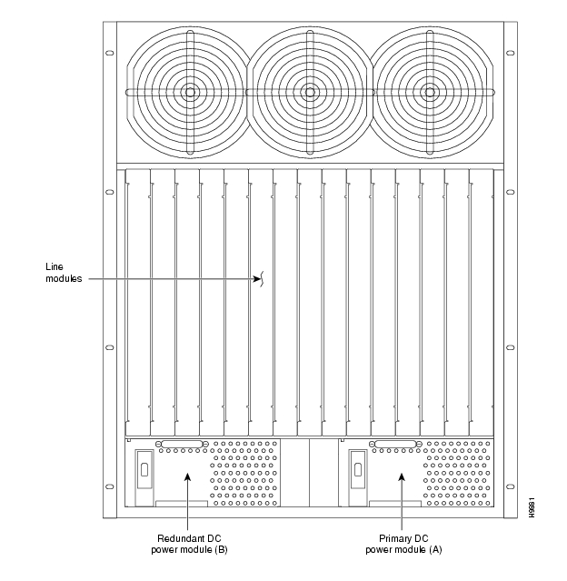
If the BPX switch shelf is DC-powered, the DC Power Entry Modules are factory-installed in the lower portion of the rear of the BPX switch shelf ( ). Locate the DC Power Entry Module(s) and make sure it/they are equipped as ordered. If the BPX switch shelf is AC-powered, an AC Power Tray is installed below it as part of the installation process.
Figure 3-1 Location of DC Power Entry Module(s), Cabinet Rear View
Preliminary Procedure:
Proceed as follows to install either an AC or DC powered BPX switch shelf, referring to and and to either for DC powered systems or for AC powered systems:
Step 1
Step 2
Note
Warning
An empty BPX switch shelf weighs 75 pounds (34 Kgs.) and requires a 2 or 3-person lift to move into place.
Step 3
Step 4
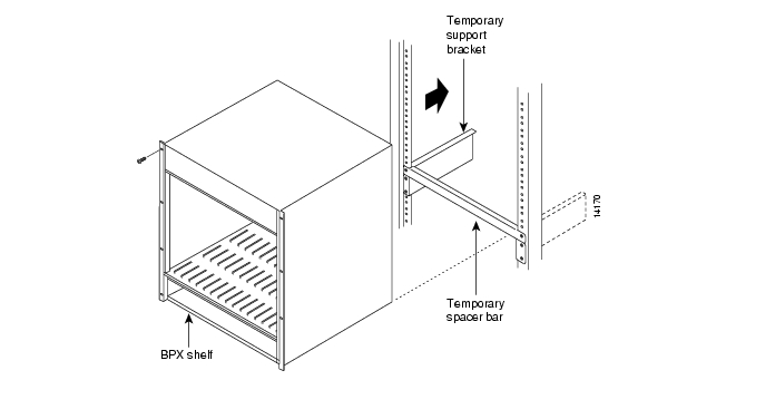
Figure 3-2 BPX Shelf Aligned with Temporary Support Brackets and Bar
Step 5
Step 6
Step 7
Step 8
Step 9
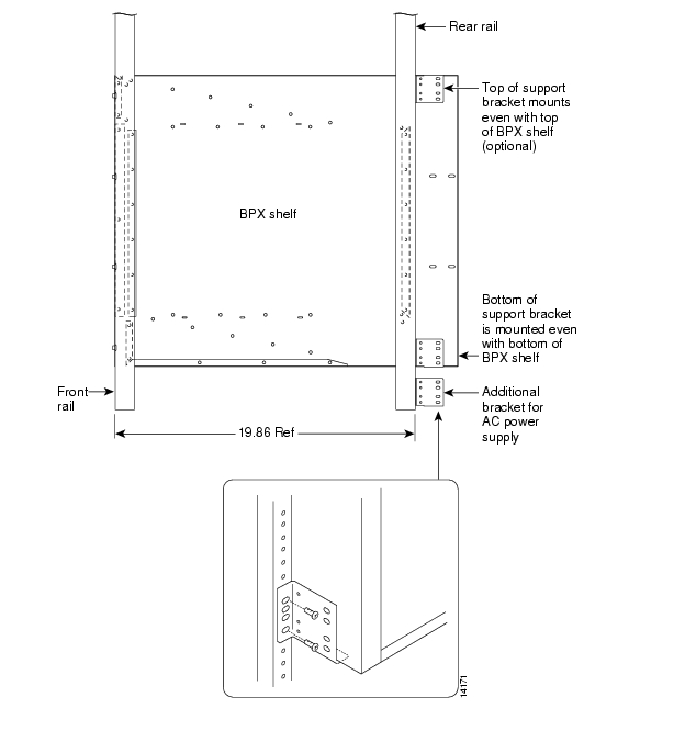
Figure 3-3 BPX Shelf with Rear Rail Mounting at Setback of 19.86 inches
Figure 3-4 Rear Mounting Brackets, with 19.86 Inch Rear Rail Setback (DC Systems)
Figure 3-5 Rear Mounting Brackets, 19.86 Inch Rear Rail Setback (AC-Systems)
![]()
![]()
![]()
![]()
![]()
![]()
![]()
![]()
Posted: Tue May 10 21:25:29 PDT 2005
All contents are Copyright © 1992--2005 Cisco Systems, Inc. All rights reserved.
Important Notices and Privacy Statement.