|
|

Table Of Contents
Installation, DC Shelf Initial Setup
5
Installation, DC Shelf Initial Setup
This chapter describes how to make the DC power connections.
Before proceeding to this chapter, the procedures should be completed, in either:
•
Chapter 3, , or
•
This chapter contains the following sections:
•
•
•
DC Power Input Connections
There are two versions of the DC-powered BPX switch as follows:
•
•
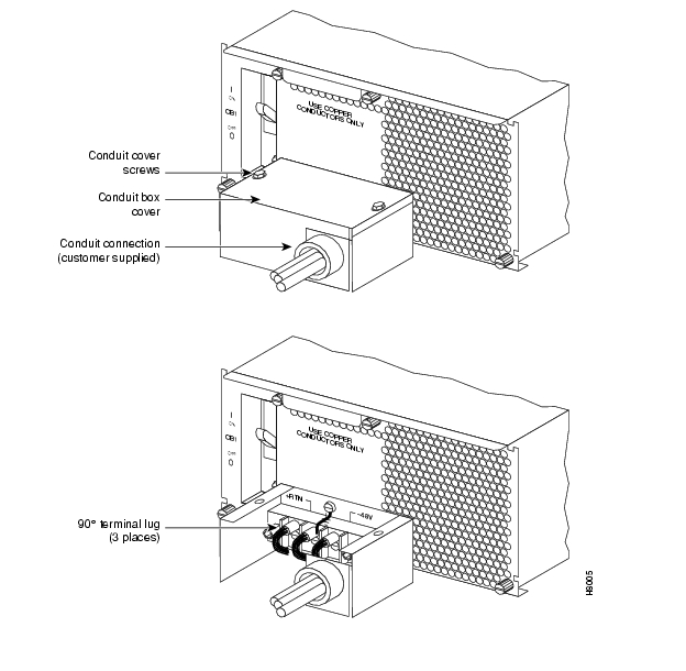
For DC systems, the wiring is connected from a 48 VDC power source to one or two DC Power Entry Modules ( ). This wiring is provided by the installer. A metallic conduit box that meets all electrical codes for attaching electrical conduit is factory-installed . A simple plastic cover is also enclosed for customers who do not require conduit protection for the input power leads . Use conduit if required by local electrical code.
Only a source that complies with the safety extra low voltage (SELV) requirements in UL1950, CSA C22.2 No. 950, EN60950 can be connected to a BPX switch DC system.
To make DC power connections to the BPX switch:
Step 1
Step 2
Step 3
Step 4
CautionEnsure that polarity of the DC input wiring is correct! Connections with reversed polarity may damage the equipment
Warning
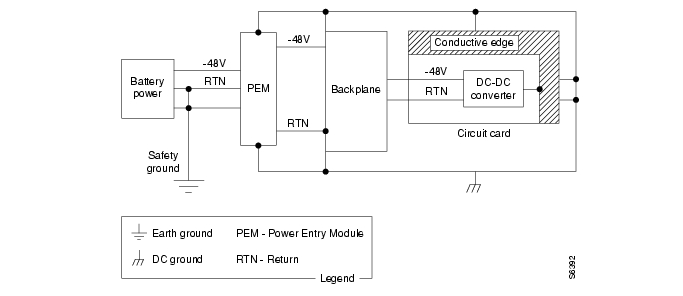
Remember that this is a positive ground system. Connect the positive lead to the +RTN terminal. Connect the negative lead to the -48V terminal. Connect the earth ground to the middle terminal labeled SAFETY GROUND. See , and . For personnel safety, the green/yellow wire must be connected to safety (earth) ground at both the equipment and at the supply side of the dc wiring.
Figure 5-1 DC Power
Step 5
Note
Step 6
Step 7
Step 8
Figure 5-2 DC Power Connections—With Conduit Box
Figure 5-3 DC Power Connections—Without Conduit Box
Card Slot Fuses
Fuses for each card slot have been added to the backplane of later versions of the BPX switch to protect against catastrophic backplane damage in the event of a shorted connector power pin. Backplane fuses should rarely, if ever, need replacement. The card slot fuses are designated F4 through F18, corresponding to card slot numbers 1 through 15, respectively.
Refer to the Cisco BPX 8600 Series Reference document, Repair and Replacement chapter, for instructions on replacement of these fuses, and contact Cisco Customer Service for assistance regarding their replacement.
CautionFor continued protection against risk of fire, replace only with the same type and rating of fuse. Fuses should only be replaced after all power to the BPX switch has been turned off.
Fan Power Fuses
Fan fuses are located on the backplane of the BPX switch to protect against catastrophic backplane damage in the event of a shorted fan cable. Backplane fuses should rarely, if ever, need replacement. The fuses are designated F1 through F3, corresponding to fans 1 through 3.
CautionRefer to the Cisco BPX 8600 Series Reference document, Repair and Replacement chapter, for instructions on replacement of these fuses, and contact Cisco Customer Service for assistance regarding their replacement.
Warning
For continued protection against risk of fire, replace only with the same type and rating of fuse. Replace fuses only after all power to the BPX switch has been turned off.
![]()
![]()
![]()
![]()
![]()
![]()
![]()
![]()
Posted: Tue May 10 21:23:41 PDT 2005
All contents are Copyright © 1992--2005 Cisco Systems, Inc. All rights reserved.
Important Notices and Privacy Statement.