|
|

This chapter provides procedures for performing the common tasks encountered during the initial installation and operation of a BPX Service Node network. This chapter includes:
Resources on BPX Service Node UNI ports and NNI trunks have to be divided between SVCs and PVCs. This is known as resource partitioning and is done through the Command Line Interface for the BPX and the AXIS.
This section provides procedures for:
The following UNI Ports, which support ATM or Frame Relay SVCs, will have their resources partitioned:
An AUSM card which will support ATM SVCs will have to be added and upped like a standard PVC port. Complete details on using the AXIS command line interface and applicable commands are described in the Cisco StrataCom AXIS Reference and AXIS Command Reference manuals. In addition, the Cisco StrataCom System Overview provides conceptual information about ATM connections and services.These procedures will concentrate on those commands that are specific to SVC resource partitioning.
Before partitioning SVC resources, you must have determined which AUSM module will be connected to ATM CPE equipment for SVCs. The AUSM port must have already been added configured, and upped as described in the AXIS manuals with these commands:
To partition SVC resources on an AUSM UNI port, follow these steps:
Step 2 cc to the AUSM slot you are going to partition.
Step 3 Enter the command cnfsvcrange, the menu shown in Figure 8-1 appears:

This command is used to partition the following resources:
Step 4 First you should reserve the desired number of LCNs. For instance, to reserve 100 LCNs starting at number 20 for an AUSM8 in slot 11 you would enter: cnfsvcrange 100 LCN 20, then press Enter. The following example shows the result:
AXISNAME.1.11.AUSM8.a > cnfsvcrange 100 LCN 20
num of res = 100, type = 1 start = 20 port = -1
Step 5 Next you have to reserve the desired number of VPIDs. For instance on an AUSM8 in slot 11, to reserve 40 VPIDs starting with number 40, you would enter: cnfsvcrange 40 VPID 40, then press Enter. The following example shows the result:
AXISNAME.1.11.AUSM8.a > cnfsvcrange 40 VPID 40
num of res = 40, type = 2 start = 40 port = -1
Step 6 Next you have to reserve the desired number of VPIs. For instance, on a AUSM8 in slot 11, to reserve 35 VPIs starting on number 0 on port 2, you would enter: cnfsvcrange 35 VPI 50 2, the press Enter. (Note that ATM SVC signaling is on VPI 0/VCI 5, so the SVC start range should begin on 0.) The following example shows a typical result of the command:
axis6.1.10.AUSM8.a > cnfsvcrange 35 VPI 0 2
num of res = 35, type = 4 start = 0 port = 2
Step 7 Finally, you can see how the SVC resources are partitioned with the dspsvcrange command. This command brings up the display shown Figure 8-2, illustrating the resources reserved on the AUSM:

Repeat the SVC resource partitioning for every AUSM module for which you want SVC support.
An FRSM card which will support Frame Relay SVCs will have to be added and upped like a standard PVC port. Complete details on using the AXIS command line interface and applicable commands are described in the Cisco StrataCom AXIS Reference and AXIS Command Reference manuals. In addition, the Cisco StrataCom System Overview provides conceptual information about Frame Relay connections.These procedures will concentrate on those commands that are specific to SVC resource partitioning.
Although FRSM commands are similar to AUSM commands, they are not identical. You must pay close attention to the syntax of the commands you enter.
Before partitioning SVC resources, you must have determined which FRSM module will be connected to Frame Relay CPE equipment for SVCs. The FRSM port must have already been added configured, and channels added as described in the AXIS manuals with these commands:
You must already have determined which FRSM ports you are going to partition before starting this procedure. To partition Frame Relay SVC resources on an FRSM UNI port, follow these steps:
Step 2 cc to the FRSM slot you are going to partition.
Step 3 You can use the dspports and dspport <port number> to find the port you are going to configure for Frame Relay SVCs and to see how the port is currently configured. The dspport command is a large screen broken in two sections as shown in Figure 8-3 and Figure 8-4:
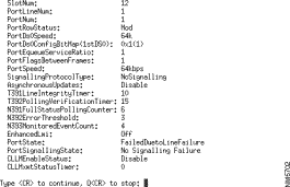
Pressing return brings up the other half of the display port screen:

Note that this screen lists the following Frame Relay SVC parameters:
The Frame Relay SVC resource partitioning parameters are configured with the xcnfrport and cnfsvcrange commands described in the next steps.
Step 4 You would enable Frame Relay SVCs for FRSM port 1 with the xcnfport command as follows:
xcnfport -pt 1-svcen 2
-pt is <PortNum> where port number is 1 -96
-svcen is <PortSvcStatus> where portSvcStatus = 1: Disable, 2: Enable
Step 5 You have to change to the shellConn to configure the SVC range. Enter shellConn.
Step 6 The FRSM cnfsvcrange has the syntax shown in Figure 8-5:

This command is used to partition the following resources:
Step 7 Next you would reserve some LCNs for the FRSM. If you wanted to reserve 50 LCNs, starting with number 16, on the FRSM in slot 12, you would enter:
cnfsvcrange "50 LCN 16"
The following example shows the results of this command:
fr_axis2.1.12.FRSM.a > cnfsvcrange "50 LCN 16"
cnfsvcrange "50 LCN 16"
num of res = 50, type = 1 start = 16 port = -1
Step 8 Next you will reserve some DLCIs for Frame Relay SVCs. If you wanted reserve 50 DLCIs starting with number 11 on a FRSM in slot 12, you would enter:
cnfsvcrange "50 DLCI 11"
The following example shows the results of this command:
fr_axis2.1.12.FRSM.a > cnfsvcrange "50 DLCI 1 1"
cnfsvcrange "50 DLCI 1 1"
num of res = 50, type = 2 start = 1 port = 1
Step 9 You can check the configured Frame Relay SVC ranges with the following command:
dspsvcrange
which results in a display similar to Figure 8-6:

Repeat the Frame Relay SVC resource partitioning for each FRSM that you want to support SVCs in your system.
A BPX ATM Service Interface (ASI) card which will support ATM SVCs will have to be added and upped like a standard PVC port. Before adding connections, an ASI line is upped with the upln command and configured with the cnfport command and upped with the upport command. Complete details on using the BPX command line interface and applicable commands are described in the Cisco StrataCom BPX Reference and Command Reference manuals. In addition, the Cisco StrataCom System Overview provides conceptual information about ATM connections. These procedures will concentrate on those commands that are specific to SVC resource partitioning.
Before partitioning SVC resources, you must have determined which ASI will support ATM SVCs. The ASI will have to have its resources partitioned to support SVCs. The following resources must be partitioned for each ASI UNI port:
To partition the ASI UNI port, follow these steps:
Step 2 Up the line and port, with the upln and upport commands, which are going to be connected to ATM CPE.
Step 3 Make sure the port is configured as UNI.
Step 4 Enter the cnfport <port num> command, as illustrated in Figure 8-7:
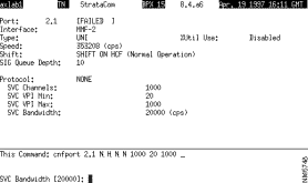
Configure the desired SVC Channels, SVC VPI Min, SVC VPI Max, and SVC Bandwidth as desired.
Step 5 Next configure the SVC Port Queue with the cnfportq <port num> command. The cnfportq menu shown in Figure 8-8 is used.

Configure the SVC Queue Pool Size with this menu. Other parameters are for PVCs.
Repeat SVC resource partitioning for every ASI port that you want to support SVCs in your BPX Service Node.
A BPX BXM card used as a UNI port can be configured to support ATM SVCs. The BXM will have to be added and upped like a standard PVC port. The BXM port will have to upped as a line (upln) to function as a UNI port.
Complete details on using the BPX command line interface and applicable commands are described in the Cisco StrataCom BPX Reference and Command Reference manuals. In addition, the Cisco StrataCom System Overview provides conceptual information about ATM connections and services. These procedures will concentrate on those commands that are specific to SVC resource partitioning.
Before partitioning SVC resources, you must have determined which BXM UNI ports will support ATM SVCs. The BXM must have its resources partitioned to support SVCs. The following resources must be partitioned:
To partition the BXM port, follow these steps:
Step 2 Up the line and port which is going to be connected to ATM CPE.
Step 3 Make sure the port is configured as UNI.
Step 4 Enter the cnfport <port num> command, shown in Figure 8-9:
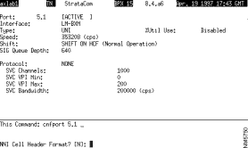
Configure the SVC Channels, SVC VPI Min, SVC VPI Max, and SVC Bandwidth as desired.
Step 5 Next you need to configure the SVC Port Queue depth with the cnfportq <portnum> command shown in Figure 8-10.
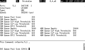
Configure the SVC Queue Pool Size parameter to a value greater than 0 (zero); the default is 0 and needs to be changed for SVCs to operate.
Partition the SVC resources for all the BXM which will support ATM SVCs in your BPX Service Node.
The BPX has two types of trunk cards which may have their resources partitioned to support SVCs.
When the BNI is used as a trunk in a BPX Service Node network, it will have to have its resources partitioned to support SVCs. The BNI is described in the Cisco StrataCom BPX Reference. Complete details on using the BPX command line interface and applicable commands are described in the Cisco StrataCom BPX Reference and Command Reference manuals. In addition, the Cisco StrataCom System Overview provides conceptual information about ATM connections and services. These procedures will concentrate on those commands that are specific to SVC resource partitioning.
The following BNI trunk resources must be partitioned for SVCs:
To partition the BNI trunk resources, follow these steps:
Step 2 Up the trunk with uptrk <trunk_num> command.
Step 3 Enter the cnftrk <trk num> command, shown in Figure 8-11:

Configure the SVC Channels and SVC Bandwidth as desired.
Step 4 Next configure the SVC Queue depth with cnftrkparms <trunk_num> command shown in Figure 8-12:
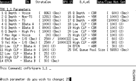
Configure the SVC Queue Pool Size as desired.
Partition the SVC resources for all the other BNIs in your BPX Service Node. This includes the BNI that is used to connect an AXIS shelf to a BPX.
When the BXM is used as a trunk in a BPX Service Node network, it will have to have its resources partitioned to support SVCs. The BXM card will have to upped as a trunk (uptrk).
The BXM is described in detail in the Cisco StrataCom BPX Reference. Complete details on using the BPX command line interface and applicable commands are described in the Cisco StrataCom BPX Reference and Command Reference manuals. In addition, StrataCom System Overview provides conceptual information about ATM connections and services. These procedures will concentrate on those commands that are specific to SVC resource partitioning.
The following BXM trunk resources must be partitioned for SVCs:
To partition the BXM trunk resources for SVCs, follow these steps:
Step 2 Make sure the BXM has been upped as a trunk with the uptrk <trunk_num> command.
Step 3 Enter the cnftrk <trk num> command, shown in Figure 8-13:
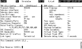
Configure the SVC Channels and SVC Bandwidth as desired.
Step 4 Next configure the SVC Queue depth with the cnftrkparms <trunk_num> command shown in Figure 8-14:

Configure the SVC Queue Pool Size as desired.
Partition the SVC resources for all the other BXMs in your BPX Service Node.
You use the ESP Configuration Interface for the initial configuration and provisioning of the ESP and BPX Service Node network. The ESP Configuration Interface was described in detail in Chapter 7, Understanding the ESP Configuration Interface. This section concentrates on how the Configuration Interface is used, and the sequence of operations. This section will use the following options of the Configuration Interface:
The next section, PNNI Provisioning and Static Routing, will use the Topology Information and PNNI Information options of the Configuration Interface.
The ESP Information menu is used to configure the ESP, and the redundant ESP when there is a redundant pair in the BPX Service Node. One of these menus must be completed for every ESP (that is BPX Service Node) in the network. To initially provision your BPX Service Node network, follow these steps:
Step 2 Select the ESP Information menu and configure:
This menu will have to be completed for every ESP in the network.
Step 3 From the ESP Information menu, press F2 to select Billing Information. Configure the following BPX Service Node billing parameters:
Step 4 For IISP nodes only, configure the Node list; from the ESP Information menu, press F6 to access the Node List menu. Next press F3 to add a Node.
Step 5 For IISP nodes only, add nodes and node prefixes and addresses. Add the Node and the Node Address or Node Prefix. (You will have to add every BPX Service Node in the network to the Node List).
Step 6 From the ESP Information menu, press F7 to access the View Shelf List. Then press F3 to access the Shelf Information menu. Configure the following:
You must add every AXIS shelf attached to the BPX at this BPX Service Node.
Next you will have to add all the UNI ports at this BPX Service Node.
To add the UNI ports, follow these steps:
Step 2 From the UNI Information menu, press F3 to Add a UNI Port.
Step 3 If the port is an ATM UNI port, configure the following:
If the port is a Frame Relay UNI port, configure the following:
You will have to add a Configuration Interface record for every UNI port at this BPX Service Node.
Step 4 Next, from the UNI Information menu, press F1 to View Port Address. From this menu you will add Port Addresses or Port Prefixes. You will have to add a Port Address or Port Prefix for every UNI port at this BPX Service Node.
Step 5 Next, from the UNI Information menu, press F3 to View Egress Screen Addresses. From this menu, you press F4 to add an UNI address or address prefix to the list of Egress Screen Addresses. You have to add every address you want to Egress Screen at this UNI port.
Step 6 Finally, from the UNI Information menu, press F6 to configure UNI port billing. From this menu, you configure:
You must repeat the UNI Configuration for each BPX Service Node.
If ILMI is not supported on a given CPE attached to the BPX Service Node, then the NSAP addresses must be configured manually. When assigning addresses you must assign a unique, valid prefix to the BPX Service Node. This same prefix should be used for all ATM CPE UNI's attached to this Service Node.
Figure 8-15 illustrates a simple network with attached CPE that do not support ILMI.
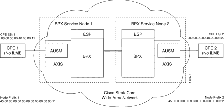
There are three important steps to remember when configuring CPE without ILMI:
Step 2 Make sure that the ATM UNI Port have been configured for no ILMI with the ESP Configuration Interface ATM UNI Information menus.
Step 3 Manually configure the CPE end station ATM addresses with the ESP Configuration Interface menus. In this case, the 13-byte Node Prefix for BPX Service Node 1 is 45.00.00.00.00.00.00.00.00.00.00.00.11 and the CPE ESI (end system identifier) is 80.000.00.00.40.00.00.11. These two parts will combine to become CPE 1's ATM address. Similarly Node Prefix 2 and CPE ESI 2 will combine to form the ATM address for CPE 2. Note that any CPE attaching to either of the BPX Service Nodes will have to use that node's prefix as the first 13 bytes of its ATM address.
If ILMI is supported on a given CPE attached to the BPX Service Node, the BPX Service Node will discover all the ATM CPE devices attached to it. (Remember that ILMI is not supported for Frame Relay SVCs.) Figure 8-16 illustrates a simple network with attached CPE that support ILMI.

In order for ILMI address registration to take place, you must:
Next you have to create an Configuration Interface record for each NNI trunk in your BPX Service Node network.
To add an NNI record, follow these steps:
Step 2 From the NNI Information menu, select F3, Add NNI Port.
Step 3 From the NNI Information menu, configure the following:
Add a record for every NNI port on the BPX Service Node.
The NNI Information records will have to completed at every BPX Service Node in the network.
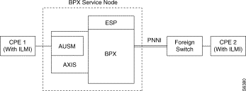
The BPX Service Node does not support ILMI over IISP links. Thus, when a foreign switch is connected to a BPX Service Node, as is shown in Figure 8-17, the address to CPE 2 will have to configured on the BPX Service Node with the ESP Configuration Interface. This address must include the Foreign Switch's Node Prefix. This address will be added to the ESP PNNI routing table as an exterior reachable address. In this example the address of CPE 1 will be automatically discovered by ILMI. A static route on the Foreign Switch will also have to be configured to the BPX Service Node. Also be sure to configure one end of the IISP link as User, and the other end as Network.

When you are connecting a foreign switch to a BPX Service Node, as shown in Figure 8-18, you have to ensure that PNNI is enabled at both ends, and if applicable that ILMI is enabled at the Foreign Switch's UNI ports.
Next you will have to configure the routing used in the BPX Service Node network. This will be either:
For static routing, IISP 3.0 or IISP 3.1 must have been configured as the Protocol Version on the NNI Information menus. If you are using IISP (static) routing, you will configure it with the Topology Information menus of the ESP Configuration Interface:
To configure static routing, follow these steps:
Step 2 From the Topology Information menu, select Add ESP Pair.
Step 3 Enter the BPX Service Node name and assign a weight to this link.
Add a pair for every pair of IISP links.
Remember, as described in Chapter 7, these ESP Pairs are only the IISP links that do not terminate on the BPX Service Node which you are configuring. Those IISP links which terminate on this BPX Service Node will have been configured with the NNI Information menus.
You configure PNNI routing from the ESP Configuration Interface using the PNNI Information options.
To configure PNNI routing, follow these steps:
Step 2 From the PNNI Information menu, configure:
Although it is not possible to discuss every type of ATM or Frame Relay CPE that can be connected to a BPX Service Node, this section provides examples of what is involved with connecting two types of Cisco CPE to the BPX Service Node:
A Cisco Frame Relay router is typically connected to a BPX Service Node's Frame Relay UNI. Cisco offers Frame Relay SVC support in the Enterprise image on Cisco platforms that include a serial or HSSI interface (Cisco 7000 and 7500 series, Cisco 4500 and 4700, Cisco 4000, Cisco 3000, and Cisco 2500 platforms).
Figure 8-19 illustrates simple BPX Service Node network with two Frame Relay SVC routers attached.
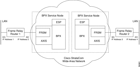
The two Cisco Frame Relay routers (Router 1 and Router 2) must be configured for proper Frame Relay SVC operation. In this figure each router has one serial interface (s0) to the Cisco StrataCom wide-area network, and one Ethernet LAN interface (e0). When configuring these routers for Frame Relay SVC operation, the important things to remember are:
The Light Stream 1010 ATM switch is Cisco System's ATM switch for workgroup and campus backbone deployment. It provides support for the following signaling and interface protocols, making it ideal as an interface for a Cisco StrataCom BPX Service Node:
The complete features of the LS1010 are described in the Cisco LS1010 manual set.
When connecting an LS1010 to the BPX Service Node, you have to ensure that:
The BPX Service Node network management is divided into three sections:
StrataView Plus provides the BPX Service Node and ESP with:
The Cisco StrataCom StrataView Plus Operations Guide contains the details for running the StrataView Plus application. This section will just provide brief procedures for using the StrataView Plus features associated with the ESP.
StrataView Plus will display an icon for each ESP in the network. The individual icons are displayed (along with AXIS shelf icons) when the BPX icon, displayed on the top-level map, is expanded. The ESP icon will be color coded to indicate its status:
To view an ESP icon on StrataView Plus, follow these steps:
Step 2 Double click on the StrataCom Network icon. The StrataView Network Topology window will appear. This map should show all the BPXes (that is, BPX Service Nodes) in your network.
Step 3 Double click on the BPX which has the desired ESP attached. A BPX window showing all the attached shelves (both AXIS and ESPs) will appear. These shelves will be color coded to indicate their status.
Figure 8-20 illustrates an expanded BPX node with an ESP attached.

To telnet to an ESP StrataView, follow these steps:
Step 2 Click on the ESP icon (or an AXIS icon if you wanted to log in to an AXIS shelf).
Step 3 Pull down the StrataCom menu from the menu bar on the window. Select Telnet (SV), shown in Figure 8-21. An XTerm window with a log in prompt for the ESP will appear.
Step 4 Log in as espuser.
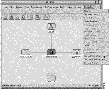
The StrataView Plus Image Download feature will transfer (tftp) a software image (a *.tar file) to the ESP. (The *.tar file will have to exist on the StrataView Plus Workstation, of course.) These images will have to be untarred and loaded on the ESP using the ESP Configuration Interface Download File from SV+ option.
To download an image to the ESP from StrataView Plus, follow these steps:
Step 2 Expand an the appropriate BPX icon on the HP OpenView map and select and ESP.
Step 3 Pull down the StrataCom option on the window's menu bar. Select Image Download. The Image Download window will appear with a list of ESPs and image files as shown in Figure 8-22.
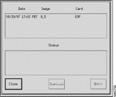
Step 4 Select one of the listed files and the Download button will become active. Click on the Download button.
StrataView Plus also provides you with the option to save or restore the configuration files created with the ESP Configuration Interface.
When you are saving ESP Configuration Files from StrataView Plus, you transfer these files, which are converted to flat ASCII files by the process, to the StrataView Plus Workstation. The files are saved by name.
To save an ESP configuration, follow these steps:
Step 2 Expand a BPX icon until attached ESP icons are shown. Select the appropriate ESP icon and pull down the StrataCom menu.
Step 3 Select Configuration Save and an AXIS or ESP selection menu will appear as shown in Figure 8-23.

Step 4 Select ESP and the Configuration Save menu, shown in Figure 8-24, will appear.
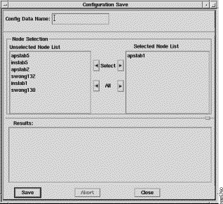
With this menu, you complete:
Config Data Name: to name the configuration file using the format ESP_DB_rel_ver
Node Selection to specify the Node or Nodes whose configuration you will save. To select the appropriated ESP:
Select it in the Unselected Node List; the press the right Select button to place it in the Selected Node List, as apslab1 is shown in Figure 8-24.
Step 5 Click the Save button. The ESP configuration file is ftped as a flat ASCII file from the ESP to the StrataView Plus Workstation.
To restore an ESP configuration, which has been previously saved, follow these steps:
Step 2 Expand a BPX icon until the attached ESP icon is shown.
Step 3 Select the ESP icon and pull down the StrataCom menu and select Configuration Restore. The Configuration Restore menu, shown in Figure 8-25, will appear.
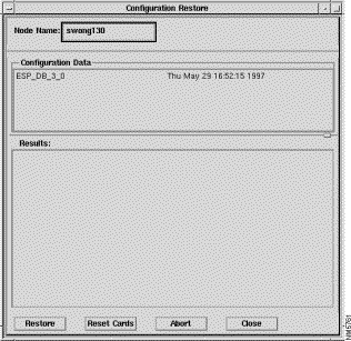
Step 4 You will be shown lists of configuration files in the Configuration Data box and the ESP node name in the Node Name box. Select the appropriate configuration file (one that you have previous saved) and click the Restore button.
This section will provide instructions for using the StrataView Plus Network Browser to monitor the ESP status:.
To access the Network Browser, follow these steps:
Step 2 Click on the Network Browser button. The Network Browser window, shown in Figure 8-26, will appear. This window will report information about all the network elements, including the Alarm State of the ESPs.
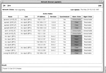
For general information on the Network Browser, see the Cisco StrataCom StrataView Plus Operations manual.
![]()
![]()
![]()
![]()
![]()
![]()
![]()
![]()
Posted: Fri Jan 19 20:18:37 PST 2001
All contents are Copyright © 1992--2001 Cisco Systems, Inc. All rights reserved.
Important Notices and Privacy Statement.