|
|

After you have rackmounted the ESP and connected the power, you must connect the physical interfaces to it. These interfaces, which are represented in Figure 6-1, are:
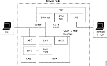
The ESP ATM NIC can be connected to either a BXM's MMF (multimode fiber) backcard or an BXM's SMF (single-mode fiber) and SMF-LR, single-mode fiber long reach (SMF-LR) backcard. When it is connected to an SMF or SMF-LR backcard, special cable assemblies with an optical attenuator subassembly must be used. Appendix B, Cable Information, contains a list of the fiber optic cables available from Cisco StrataCom.
Each ESP communicates with the connected BPX and AXIS via a standard 802.3 Ethernet. Ethernet data delivered through this interface can traverse through a router or 10BaseT hub to form direct connections between the ESP, the BPX, and the AXIS, as well as to the StrataView Plus Workstation.
Figure 6-2 shows the location of the connectors for the ESP physical interfaces. Although only an ESP-AC model is shown in Figure 6-2, the connectors will be in the same location on a ESP-DC Model.

You can attach a terminal (or PC running a terminal emulation program, such as, ProComm`) to the ESP to perform some of the configuration locally.
Attach your terminal cable, typically a null modem cable, to the A/B (Terminal) connector on the ESP back panel, shown in Figure 6-2. This is an asynchronous ttya port on the UNIX-based ESP. Your terminal (or PC and emulation software) must be set to match the ESP communication parameters:
The ATM NIC has an SC multimode fiber (MMF) connector. This molded plastic connector is keyed to accept an multimode fiber cable with transmit (TX) on the left and receive (RX) on the right. The ATM NIC connects to an a BXM-155 (an OC3 ATM interface) with one of the following backcards:
ESP ATM Network Interface card connections to a BXM's single-mode fiber (SMF) and single-mode fiber long reach (SMF-LR) backcard will require special cable assembles with an optical attenuator to reduce the transmitted power from the BXM backcard. These cable assemblies are described in Appendix B in the section Fiber Optic Cable Assemblies.
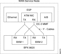
Before connecting your ESP to the BXM, you must have already determined if you are going to use BXM redundancy. If so you, you will need the appropriate Y-cables, depending on which BXM-155 backcards are in place. The fiber optic Y-cable assemblies are described in Appendix B in the section Fiber Optic Cable Assemblies.
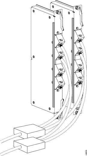
Remember as shown in Figure 6-3, the Y-cables are connected from the TX (transmit) connector on the ESP ATM NIC to the RX (receive) connector on the two BXM backcards. Also, the RX (receive) connector on the ATM NIC will be connected to the TX (transmit) connectors on the two BXM backcards. Figure 6-4 shows a sample of the Y-end of the cables connected to BXM backcards. BPX cards must be configured for Y-cable redundancy using the addyred BPX command.
To connect the ATM NIC to the BPX, follow these steps:
Step 2 Connect the appropriate fiber cable with SC connectors to the ATM NIC and then to the BXM backcard.
Step 3 Log in to the BPX.
Step 4 If appropriate, add Y-cable redundancy with the command addyred.
Step 5 Up the trunk with the uptrk command. (Note that this command configures all the ports on the BXM card to be trunks.)
Step 6 Configure the trunk with cnftrk command. Figure 6-5 illustrates the configuration parameters required between the BXM and the ESP ATM NIC.
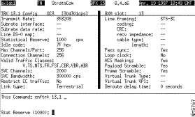
The standard BXM parameters can be accepted for most parameters on this trunk as shown. You will have to enter a value, however, for SVC Channels (shown as 2000) and SVC Bandwidth (shown as 300000 cps). These are SVC resource partitioning parameters. Resource partitioning is described in more detail in Chapter 8. Note that the OC-3 Line framing is the default STS-3C.
Step 7 Next configure the SVC Queue Pool Size with the cnftrkparm command. The Configure Trunk Parameters screen is shown in Figure 6-6.
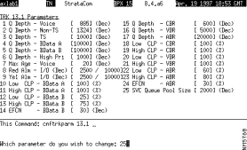
The only parameter that needs to be changed with this menu is 25 SVC Queue Pool Size. Enter 2000 for this value as shown.
Since the ESP is a feeder shelf from the BPX's perspective, you still have to add the ESP to the BPX with the addshelf p command. Adding it as a shelf allows the StrataView Plus discovery mechanism to find the ESP. This should be done, however, after the ESP has been connected to a LAN, been configured, and rebooted. Using the addshelf p command is described in the section Adding the ESP Shelf to the BPX.
The ESP connects to an Ethernet LAN to communicate with the BPX, the AXIS, and with the StrataView Plus (SV+) Workstation. Figure 6-7 illustrates the Ethernet connections.
Each ESP communicates with the connected BPX and AXIS via a standard 802.3 Ethernet. Ethernet data delivered through this interface can traverse through a router or 10BaseT hub to form direct connections between the ESP, the BPX, and the AXIS, as well as to the StrataView Plus Workstation.

Normally the ESP is connected from its 10Base-T connector to an Ethernet Hub. Typically, the BPX BCC's LAN port, and an StrataView Plus Workstation are also connected to this same Ethernet segment.
You may have to modify some of the ESP UNIX operating system (i.e., Solaris 2.5) files for your local LAN environment. To do this, you will need to use a text editor such as vi to modify files and a few simple Sun operating system (Solaris) commands.
vi is a UNIX-based screen editor which can be used to make some minor modifications to the UNIX-based files. You can find out more about vi, by typing man vi at the ESP UNIX prompt and pressing Enter. In vi there is a command mode and an editing (i.e., insertion) mode. Most commands are entered from the command mode; while the file is actually modified in the editing mode. You quit the editing mode with ESC. Since only minor changes need to be made to ESP UNIX files, you should only need to know a few commands:
When you are logged in to the ESP, you can find out the use and syntax of operating system commands with the man page command; for instance, enter man login to find out about the login command.
A quick procedure for editing any of the files:
Step 2 vi filename.
Step 3 Position cursor where you want to add or change text (use the arrow keys or h, j, k, l).
Step 4 Enter o to add a new line, i to edit a line, or R to enter overwrite mode.
Step 5 Enter your text.
Step 6 Hit ESC when you are done adding text. You are now back in the command mode.
Step 7 Enter ZZ to save the file. (You can use more filename to check that file has been modified).
Before beginning this procedure, you must know what the IP address for the ESP (and the redundant ESP if they are being installed as a redundant pair) the subnet mask, and the hostname(s) will be.
After checking with your system administrator, set the IP address, hostname, subnetmask, and other parameters necessary for operating the ESP in your local area network environment, as follows:
Step 2 Log in to ESP as superuser.
 | Caution Once you start changing host names and IP addresses, you must make sure you complete all the files. Do not turn off power or reboot in the middle of this process or you could disable your ESP. |
Step 3 Use vi to screen edit the file /etc/hosts and add the IP address for the ESP and the IP address for the SV+ Workstation.
For direct Ethernet connection where, for example, you have an SV+ Workstation with a hostname of nms and an IP address of 200.1.2.3, a BPX with hostname of bpx1 and an IP address of 200.1.2.5, and a ESP with a hostname of esp1 and an IP address of 200.1.2.4, you would add the two lines, shown in bold type, to the hosts file:
Contents of /etc/hosts
#
127.0.0.1	localhost
#
200.1.2.4	esp1	loghost	# ESP1 (ESP 1 local Ethernet port)

200.1.2.3	nms		# SV+ Workstation

200.1.2.5	bpx1	 	# BPX1 LAN Port
# End of hosts
Step 4 If required for your local network, use vi to screen edit the file /etc/networks, which will appear similar to the following:
Contents of /etc/networks file:
#
# The loopback network is used only for intra-machine communication
#
loopback	127
#
# Internet networks
#
arpanet	10	arpa	# Historical
nms-net	200.1.2		# SV+ network

# End of networks
For our example, the line in bold text, nms-net . . ., is added to the networks file.
Step 5 If required for your local network, use vi to screen edit the file /etc/netmasks to add the appropriate subnet mask for your LAN segment.
Step 6 If required for your local network, use vi to screen edit the file /etc/hostname.le0 to name the ESP ethernet port.
Step 7 If required for your local network, use vi to screen edit the file /etc/nodename to name the ESP node, and verify that this name is the same name as /etc/hostname.le0.
Step 8 Use the date command to set the local date and time.
Remain logged in to the ESP to complete the next section, Run ApsCreateCnfg.
The first time you connect an ESP to the BPX and power it up, you have to run the ESP configuration program (ApsCreateCnfg) to prompt it with enough configuration information to start the ESP Configuration Interface.
The ESP has been configured at the factory as a Standalone unit. If you are installing it as a redundant system (2 ESPs in the same BPX Service Node), you must know the IP address for the redundant (peer) ESP.
To run APS CreateCfg, follow these steps:
cd /opt/aps/scripts
Step 2 Start the ESP configuration program by entering:
ApsCreateCnfg
and pressing Return.
Step 3 The program will run with the following messages and series of prompts. You will be asked (as is shown in the following example) to select a start up state, a start up role, and to enter the IP address of the peer ESP. The ESP configuration will prompt you as follows:
APS startup configuration:

Enter startup state (0=SHUTDOWN, 1=OOS, 2=INSRVC) :[0]
Enter 0, 1, or 2 to select the startup state. The default is 0. This is just an initialization parameter and can be changed with the ESP Configuration Interface, once it is running. You will typically enter 1 for Out of Service here.
Enter startup role (0=STANDALONE, 1=ACTIVE, 2=STANDBY) :[0]
Select a startup role. Again this is only an initialization parameter and can be changed once the ESP Configuration Interface is running. (If you select 0 for standalone, you will not be asked to enter a peer IP address. Typically during a first-time installation, you will enter 2 for standby here.
Enter network peer ip addr :
If you are installing a redundant pair of ESPs (or if you are adding a second ESP to the BPX Service Node) you must enter the peer ESP IP address here, for example 195.168.4.127.
Step 4 After you enter the peer IP address the program concludes with the following messages:
Creating Config file
Config file created
Step 5 Now reboot the ESP by entering the reboot command:
reboot
The ESP will restart and prompt you to login as espuser. The first time you login as espuser, you will be prompted to change the ESP password. After changing the password, the ESP will start with the ESP processes running and launch the ESP Configuration Interface. (The ESP Configuration Interface is described in detail in Chapter 7.)
From this time forward, you should log in using your espuser password.
After the you have run ApsCreateCnfg and started the ESP Configuration Interface, you should add the ESP as a shelf to the BPX. To add the ESP shelf, follow these steps:
Step 2 Add the ESP shelf to the BPX Service Node with the addshelf p command. For the ESP attached to axlab1.13.2, this command would be:
addshelf 13.2 p
This will allow StrataView Plus to discover the ESP as a shelf attached to the BXM. It will also allow the BPX to exchange its name and IP address with the ESP using the Annex G protocol.
If you are connecting redundant ESPs in your Service Node, repeat the following sections for the redundant unit:
BPX installation and configuration are covered in the Cisco StrataCom BPX Installation and BPX Reference manuals. During the configuration of Service Node interfaces, you must make sure that the BPX IP address, SNMP parameters, and Network IP address are set consistent with your local area network (Ethernet LAN). Use the following BPX commands to set these parameters:
The use of these commands is covered in the Cisco StrataCom Command Reference or the Cisco StrataCom Super User Command Reference. Super User commands must only be used by authorized personnel, and must be used carefully.
AXIS installation and configuration are covered in the Cisco StrataCom AXIS Reference. During the configuration of Service Node interfaces, you must make sure that the AXIS IP address is set up consistent with your local area network (Ethernet LAN). Use the following AXIS command to set the proper IP addresses:
cnfifip "-ip <ip address> -if <interface type> -msk <subnet mask address> -bc <broadcast address>"
The use of this command is covered in the Cisco StrataCom AXIS Command Reference.
After you have connected and configured the ESP(s), you should log in (or have someone log in) to the StrataView Plus Workstation and ping the ESP to ensure that they are communicating.
The rest of the configuration and provisioning of the Service Node and SVC services are described in Chapter 8. Much of this configuration and provisioning is done with the ESP Configuration Interface, which is described in detail in Chapter 7.
![]()
![]()
![]()
![]()
![]()
![]()
![]()
![]()
Posted: Fri Jan 19 20:28:09 PST 2001
All contents are Copyright © 1992--2001 Cisco Systems, Inc. All rights reserved.
Important Notices and Privacy Statement.