|
|

This appendix provides information about the ESP AC power cables, fiber optic cable assemblies, and includes an illustration of a sample null modem cable.
For North America, Cisco StrataCom provides a 6-foot (1.8m), 3-conductor cord with an IEC 320 C-13 appliance coupler for mating with the ESP on the system end. The other end of the power cord should be a grounding-type attachment plug as described in the paragraphs that follow.
For those countries not appearing in the preceding list, use a power cord with an IEC 320 C-13 appliance coupler for the system-end and an appropriate grounding-type attachment plug at the other end in accordance with local standards.
Source-end connector information is not available for all countries, so local codes must be known or obtained by either the customer or installer. Table B-1 lists the AC-power cables available from Cisco StrataCom for the ESP.
| Part Number | Description |
590060 | Power Core 115/10 A; To be used in North America |
590061 | Power Cord with CEE 7/5 ("Schuko") plug; |
590062 | Power Cord with AS3112 plug: To be used in Australia, New Zealand, Fiji |
590063 | Power Cord with BS1363 plug; To be used in Great Britain, Hong Kong, and Ireland |
590064 | Power Cord with CEI 23-16/VII plug; To be used in Italy |
590065 | Power Cord with IEC 320 style plug; To be used in Japan |
Table B-2 lists the fiber optic cable assemblies available from Cisco StrataCom for connecting the ESP's ATM OC-3 Network Interface Card to the BPX's BXM card. Note that ESP fiber optic cable assemblies come in pairs, one for transmit and one for receive. These cable assemblies consist of several subassemblies as described in the following sections.
| Model Number | Description |
CAB-ESP-MMF | Fiber optic cables for direct connection between the ESP's ATM Network Interface Card and a BPX's BXM card with a multimode interface backcard (LM-OC3-MMF). |
CAB-ESP-MMF-Y | Fiber optic Y-cables for connecting the ESP's ATM Network Interface Card to redundant BPX's BXM cards with multimode interface backcards (LM-OC3-MMFs). |
CAB-ESP-SMF | Fiber optic cables, plus 10dB of optical attenuation, for connecting the ESP's ATM Network Interface Card to a BPX's BXM card with a single-mode fiber (SMF) interface backcard. |
CAB-ESP-SMF-Y | Fiber optic Y-cables, plus 10dB of optical attenuation, for connecting the ESP's ATM Network Interface Card to redundant BPX BXM cards with single-mode fiber (SMF) interface backcards. |
CAB-ESP-SMF-LR | Fiber optic cables, plus 15dB of optical attenuation, for connecting the ESP's ATM Network Interface Card to a BPX's BXM card with a single-mode interface long-reach (SMF-LR) interface backcard. |
CAB-ESP-SMF-LR-Y | Fiber optic Y-cables, plus 15dB of optical attenuation, for connecting the ESP's ATM Network Interface Card to redundant BPX BXM cards with single-mode interface long-reach (SMF-LR) backcards. |
Note: Y-cables are for connecting the ESP's ATM Network Interface Card to redundant BXMs. They do not indicate that the ESP is connected in the redundant pair configuration (that is, an active and standby ESP). | |
The ESP's fiber optic cable assemblies are assembled out of the following subassemblies:


The fiber optic cable assemblies are assembled out of the subassemblies. Male connectors are inserted into female connectors; the ends of the subassemblies are keyed with a groove and a notch so that the pieces are connect together correctly. The following sections describe how the fiber optic cable assemblies are interconnected.
CAB-ESP-MMF assembly consists of two 72-1312-01 multimode fiber optic cables. Figure B-7 illustrates how these cables are connected to a BXM's multimode fiber optic backcard.

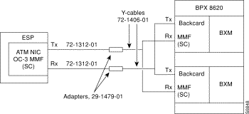
CAB-ESP-MMF-Y assembly consists of 2 Y-cable assemblies (72-1406-01) for connecting to redundant BXM multimode fiber interface backcards. If necessary, these 2 Y-cables can be extended with the optional adapters (29-1479-01) and multimode fiber optic cables (72-1312-01). The adapter plugs into the Y cable, converting its male connector to a female connector; then the 72-1312-01 cable can be added, extending the Y-piece by 10 feet.
Figure B-8 illustrates how the multimode fiber optic Y-cables are connected to redundant MMF backcards and to the ESP ATM Network Interface Card.

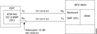
When connecting the ESP ATM Network Interface Card to a BXM single-mode fiber (SMF) interface the power from the transmit side of the BXM SMF backcard has to be reduced. The CAB-ESP-SMF fiber optic cable assembly consists of a 72-1312-01 multimode fiber optic cable, a 72-1317-01 single-mode fiber optic cable, and a 10 dB optical attenuator (29-1533-01). The optical attenuator plugs into the ESP's ATM NIC Rx (receive) connector, and the 72-1312-01 cable connects to the attenuator as shown in Figure B-9. The connection from the ESP ATM NIC Tx connector to the BXM SMF backcard's Rx connector does not require attenuation, and uses the 72-1312-01 multimode fiber optic cable.

When connecting redundant BXM SMF backcards to the ESP's ATM Network Interface Card the optical power from the BXM's transmit (Tx) side must be attenuated. CAB-ESP-SMF-Y assembly consists a 10 dB optical attenuator (29-1533-01) and 2 Y-cable assemblies (72-1406-01 and 72-1247-01) for connecting to redundant BXM single-mode fiber (SMF) interface backcards. If necessary, these 2 Y-cables can be extended with the optional adapters (29-1479-01) and fiber optic cables (72-1312-01 and 72-1317-01). The adapter plugs into the Y cable, converting its male connector to a female connector; then the 72-1312-01 or 72-1317-01 cable can be added, extending the Y-piece by 10 feet. The 10 dB attenuator (29-1533-01) should be connected to the Rx connector on the ESP's ATM Network Interface Card. The connection from the ESP ATM NIC Tx connector to the BXM SMF backcard's Rx connector does not require attenuation.
Figure B-10 illustrates how the CAB-ESP-SMF-Y cable assemblies are connected to redundant SMF backcards and to the ESP ATM Network Interface Card.

When connecting the ESP ATM Network Interface Card to BXM single-mode fiber long reach (SMF-LR) interface the power from the transmit side of the BXM SMF-LR backcard has to be reduced. The CAB-ESP-SMF fiber optic cable assembly consists of a 72-1312-01 multimode fiber optic cable, a 72-1317-01 single-mode fiber optic cable, and a 15 dB optical attenuator (29-1532-01). The optical attenuator plugs into the ESP's ATM NIC Rx (receive ) connector, and the 72-1312-01 cable connects to the attenuator as shown in Figure B-11. The connection from the ESP ATM NIC Tx connector to the BXM SMF-LR backcard Rx connector does not require attenuation, and uses the 72-1312-01 multimode fiber optic cable.

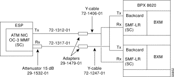
When connecting redundant BXM SMF-LR backcards to the ESP's ATM Network Interface Card the optical power from the BXM's SMF-LR backcard transmit (Tx) side must be attenuated. CAB-ESP-SMF-LR-Y assembly consists a 15 dB optical attenuator (29-1532-01) and 2 Y-cable assemblies (72-1406-01 and 72-1247-01) for connecting to redundant BXM single-mode fiber long-reach (SMF-LR) interface backcards. If necessary, these 2 Y-cables can be extended with the optional adapters (29-147901) and fiber optic cables (72-1312-01 and 72-1317-01). The adapter plugs into the Y cable, converting its male connector to a female connector; then the 72-1312-01 or 72-1317-01 cable can be added, extending the Y-piece by 10 feet. The 15 dB attenuator (29-1532-01) should be connected to the Rx connector on the ESP's ATM Network Interface Card. The connection from the ESP ATM NIC Tx connector to the BXM backcard Rx connector does not require attenuation.
Figure B-12 illustrates how the CAB-ESP-SMF-LR-Y cable assemblies are connected to redundant SMF-LR backcards and to the ESP ATM Network Interface Card.

Figure B-13 shows a typical null modem cable. Cisco-StrataCom does not supply this cable.
![]()
![]()
![]()
![]()
![]()
![]()
![]()
![]()
Posted: Fri Jan 19 20:29:04 PST 2001
All contents are Copyright © 1992--2001 Cisco Systems, Inc. All rights reserved.
Important Notices and Privacy Statement.