|
|

This chapter describes ATM Switched Virtual Circuits as they are implemented by the Cisco StrataCom BPX Service Node. This chapter includes:
A PVC signaling channel is configured between the ATM CPE, across the ATM UNI, and the BPX Service Node. The signaling channel is configured to pass signaling messages between the ATM CPE and the BPX Service Node and Cisco StrataCom network. These messages contain information elements, defined by the ATM Forum 3.0/3.1 specifications, and are used to dynamically establish, maintain, and clear ATM connections at the ATM UNI. This signaling channel will terminate on the ESP ATM NIC card as shown in Figure 2-1.
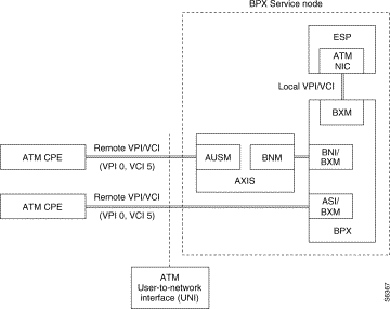
As shown in Figure 2-1, this signaling channel PVC uses VPI 0 and VCI 5 at the remote end, that is at the ATM UNI, as defined by the ATM Forum specifications. (Note that ILMI address registration will use VPI 0 and VCI 16, and PNNI uses VPI 0 and VCI 18.) The local VPI/VCI is configured during the provisioning of the BPX Service Node with the ESP Configuration Interface. Note that local and remote VPI VCIs are defined from the ESP viewpoint. The ESP software assigns both the local and remote VPI/VCIs for the signaling channels.
The BPX Service Node is compliant with either of the following ATM Forum UNI protocol versions:
These ATM Forum specifications define interoperability standards between ATM-based products (a router or an ATM switch like the BPX Service Node) located in a private network and the ATM switches within public carrier networks. The ATM Forum specifications include:
The appropriate ATM Forum protocol version is configured for each ATM UNI during the provisioning of the BPX Service Node with the ESP Configuration Interface.
To establish ATM SVCs, each ATM UNI endsystem must have an address that uniquely identifies an ATM endpoint. The ATM Forum has adapted the subnetwork model of addressing, in which the ATM layer is responsible for mapping network layer addresses to ATM addresses. Several ATM address formats have been developed--one for public networks and three for private networks. Typically, public ATM networks will use E.164 numbers, which are also used by Narrowband Integrated Services Digital Network (N-ISDN) networks.
Figure 2-2 shows the format of private ATM addresses. The three formats are Data Country Code (DCC), International Code Designator (ICD), and Network Service Access Point (NSAP) encapsulated E.164 addresses.
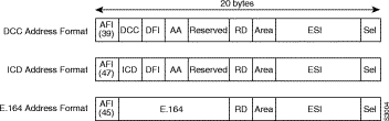
The fields of an ATM address are as follows:
AFI-1 byte of authority and format identifier. The AFI field identifies the type of address. The defined values are 45, 47, and 39 for E.164, ICD, and DCC addresses, respectively.
DCC-2 bytes of data country code.
DFI-1 byte.
AA-2 bytes of administrative authority.
RD-2 bytes of routing domain.
Area-2 bytes of area identifier.
ESI-6 bytes of end system identifier, which is an IEEE 802 Media Access Control (MAC) address.
Sel-1 byte of NSAP selector.
ICD-2 bytes of international code designator.
E.164-8 bytes of Integrated Services Digital Network (ISDN) telephone number; as shown above the native E.164 address is encapsulated in a private ATM address.
The ATM address formats are modeled on ISO NSAP addresses, but they identify SubNetwork Point of Attachment (SNPA) addresses. Incorporating the MAC address into the ATM address makes it easy to map ATM addresses into existing LANs.
In addition to the private ATM address formats defined by the ATM Forum, the BPX Service Node also supports Native E.164 addresses. E.164 addresses are defined by the ITU-T for international telecommunication numbering, and are an evolution of standard telephone numbers.
The BPX Service Node allows you to configure up to a 15-digit E-164 address. (E.164 addresses are the Frame Relay SVC UNI port default; they are described in greater detail in Chapter 3.)
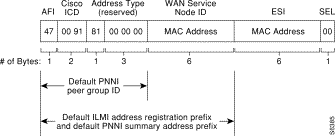
Figure 2-3 illustrates the default BPX Service Node ATM address, an NSAP ICD address. This ATM address is based on the ESP MAC address. This scheme allows all BPX Service Nodes to auto-configure within the same Peer Group at level 56 because they all share the same 7-octet prefix, 0x 47 0091 8100 0000. Cisco has been assigned the 47.0091 ICD prefix. (PNNI routing is described in Chapter 4.)
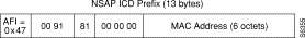
The first 13 bytes of the BPX Service Node ATM address comprise the NSAP ICD prefix shown in Figure 2-4. This is the default address prefix used for ILMI address registration. As shown in Figure 2-4, the first 7 bytes are always 47 0091 8100 0000, followed by the ESP MAC address, 6 bytes. This unique prefix identifies the BPX Service Node. This is the default UNI port prefix and allows the remaining 7 bytes of an ATM address to be configured by the ILMI address registration with the ATM CPE (ATM end user).
To establish ATM connections at the UNI, both the ATM CPE (end user) and the BPX Service Node (ATM network) must know the ATM address(es) which are in effect at that UNI. These ATM addresses can then be used in Calling Party Number information elements of signaling messages sent by the user, and in Called Party Number information elements of signaling messages sent to the user. The ILMI Address Registration procedures defined by the ATM Forum provide the means for the dynamic exchange of addressing information between the user and the network at the UNI, at initialization and at other times as required. This dynamic exchange between ATM CPE and the BPX Service Node allows them to establish the ATM address(es) in effect.
ILMI address registration reduces the need for the manual configuration of ATM CPE (end users) attached to the BPX Service Node.
ILMI address registration is either enabled or disabled for each ATM UNI Port during the provisioning of the BPX Service Node with the ESP Configuration Interface.
At the terminating node the SETUP message is processed as follows:
Screening functions are described in the next section and routing functions are described in Chapter 4.
The BPX Service Node supports three forms of screening:
Incoming Called Number (Ingress) screening filters incoming Called Party Numbers against an Incoming Called Number Screening List. A incoming call whose Called Party Number matches an address on the Ingress Screening List is rejected or accepted depending on the screening policy selected for the port - disallowed or allowed. Screening numbers may be 1-through 20-digit NSAP numbers or 1-through-15 digit native E.164 numbers. The address match is based on the length of the screening number. This allows all addresses that share a common prefix to be screened using a single screening prefix.
If the port has a disallowed screening policy then the Called Number Screening List contains a list of Called Numbers to which calls cannot be made.
If the port has an allowed screening policy then the Called Number Screening List contains a list of Called Numbers to which calls can be made. Incoming calls whose Called Numbers are not on the list are rejected.
Calls to specific destination addresses can therefore be blocked or accepted.
Outgoing Calling Number (Egress) screening filters outgoing Calling Party Numbers against an Outgoing Calling Number Screening List. A outgoing call whose Calling Party Number matches an address on the Egress Screening List is rejected or accepted depending on the screening policy selected for the port - disallowed or allowed. Screening numbers may be 1 through 20 digit NSAP numbers or 1- through 15-digit native E.164 numbers. The address match is based on the length of the screening number. This allows all addresses that share a common prefix to be screened using a single screening prefix.
If the port has a disallowed screening policy then the Calling Number Screening List contains a list of Calling Numbers from which calls cannot be accepted.
If the port has an allowed screening policy then the Calling Number Screening List contains a list of Calling Numbers from which calls can be accepted. Outgoing calls whose Calling Numbers are not on the list are rejected.
Calls from specific source addresses can therefore be blocked or accepted.
When an ATM CPE, that is ATM end user, connects to the BPX Service Node network, it is essentially making a contract with the network based on quality of service (QoS) parameters. This contract specifies an envelope that describes the intended traffic flow. This envelope includes values for peak bandwidth, average sustained bandwidth, and burst size.
It is the responsibility of the ATM CPE device to adhere to the contract by means of traffic shaping. Traffic shaping is the use of queues to constrain data bursts, limit peak data rate, and smooth jitter so that the traffic will fit within the agreed upon envelope.
The Cisco StrataCom BPX Service Nodes have the option of using traffic policing to enforce the contract. The BPX Service Node uses the following two methods to police traffic from ATM CPE into the network:
Connection Admission Control (CAC) verifies that sufficient network resources are available to accept the call. The desired ATM traffic contract is specified in the Bearer Capability, the Traffic Descriptor, and Quality of Service (QoS) information elements of the Setup message. These UNI signaling Setup message elements are mapped to Usage Parameter Control (UPC) parameters in the BPX Service Node.
When the BPX Service Node receives a Setup message, the following processing, which includes Connection Admission Control (CAC), occurs:
The Usage Parameter Control (UPC) implemented for ATM SVCs is the same UPC that is implemented for traditional Cisco StrataCom ATM networks. The ATM UNI ports in the BPX Service Node, that is the AXIS AUSM, BPX BXM or ASI-T3, support single and dual leaky bucket algorithms as applicable to control admission to the network. The BPX ASI-OC3 supports single leaky bucket UPC. The BPX BNI is a trunk card and does not support UPC.
When the ATM CPE requests a connection from the network, the Bearer Class and the Traffic Type information elements in the Bearer Capability messages are examined to determine the BPX Service Node service type. The traffic descriptor parameters in the ATM User Cell Rate (UNI 3.0) information element or the ATM Traffic Descriptor (UNI 3.1) information elements are examined to determine allowable combinations and to set up an appropriate UPC configuration.
The BPX Service Node UPC is implemented according to the ATM Forum 3.0/3.1 Traffic Management specification.
The BPX Service Node supports point-to-point ATM SVC connections. These connections, which can be unidirectional or bidirectional, support the following features:
Figure 2-5 illustrates a simple point-to-point switched channel connection. The dotted line indicates the signaling connection, and the solid line indicates the actual data transfer that occurs after the call is setup. Routing across the Cisco StrataCom network will be discussed in Chapter 4, Networking.

A typical call setup would follow this sequence:
Step 2 ATM CPE 1 initiates a Call Setup message. This message is passed from the ATM UNI port to ESP of the BPX Service Node through a signaling permanent virtual circuit (PVC). Remember this signaling PVC will use VPI 0/VCI 5.
Step 3 The ESP processes this message by:
Step 4 When the circuit is built ESP 1 sends a Setup message to ATM CPE 2.
Step 5 When the end user at ATM CPE 2 accepts the call, ATM CPE 2 sends Connect message back to across the network to the ESP at the originating end BPX Service Node.
Step 6 ESP at the BPX Service Node relays the Connect message back to ATM CPE 1 and, at the same time, sends a Connect Acknowledge message to ATM CPE 2. The call setup procedure is completed.
And a typical call disconnect would follow this sequence:
Step 2 The ESP instructs the BPX Service Node to clear the call. The Release message is again sent from the associated ESP across the network to the ESP at the far end BPX Service Node.
Step 3 The circuit is removed by the ESP at the BPX Service Node which created it, and a Call Release message is sent to the other end user, i.e., ATM CPE 2.
Step 4 After the end user acknowledges the Release message, the call is cleared.
The BPX Service Node at the originating or terminating ends of the call, depending on the Billing configuration can generate a Call Detail Record (CDR). The CDR includes the call parameters, timing information, and Cell counts. Call Detail Records are written to files on the ESP.
Each BPX Service Node also keeps other statistics for maintenance and diagnostic purposes.
See Appendix D for the ATM specifications to which the BPX Service Node complies.
![]()
![]()
![]()
![]()
![]()
![]()
![]()
![]()
Posted: Fri Jan 19 20:20:57 PST 2001
All contents are Copyright © 1992--2001 Cisco Systems, Inc. All rights reserved.
Important Notices and Privacy Statement.