|
|

The BPX Service Node provides two types of routing protocols for an ATM (or Frame Relay) SVC network:
The ATM routing protocol is necessary to establish switched virtual circuits between ATM end users, that is, ATM CPE.
This chapter includes descriptions of the following:
The BPX Service Node's implementation of NNI protocol provides the following functions:
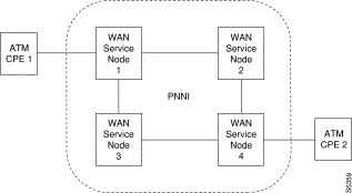
The Cisco StrataCom ATM network composed of BPX Service Nodes supports a single peer group PNNI implementation, based upon the ATM Forum's Specification Version 1.0. A peer group is a collection of logical nodes, that is, BPX Service Nodes, that exchange information with other members of the group. In a network with a single hierarchical level, each participating BPX Service Node, that is ATM switching system, is a PNNI Node. A single peer group allows all members to maintain an identical view of the group. Each BPX Service Node maintains the entire topology of the network. For example, in the simple network of Figure 4-1, each BPX Service Node knows the paths between ATM CPE 1 and ATM CPE 2, including status information and available resources on each node along the way.
The PNNI software runs on the ESP of the BPX Service Node. Its main function is to create a routing database for use by the SVC software. Figure 4-2 illustrates the logical interfaces of PNNI and SVC functions within the BPX Service Node. The PNNI routing entity is relatively independent in the integrated system.
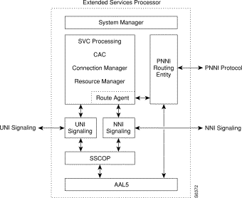
The PNNI routing entity in the BPX Service Node maintains routing tables for use by the SVC processing function (that is the Call Processor) of the ESP. The PNNI routing entity calculates the routing tables based on the most recent network resource availability information. It also keeps track of changes to local resources and floods this information to other BPX Service Nodes in the network.
When PNNI receives a route request, it looks up the pre-calculated routing database for the given destination along with the requested service class and traffic metrics parameters. If a satisfactory route exists, the associated Designated Transit List (DTL) is returned as a response. The DTL is a list of nodes, and optionally link Ids, that completely specify a path across a single PNNI peer group.
The following sections describe these PNNI operating parameters as they apply to the Cisco StrataCom BPX Service Node:
The PNNI entity maintains a topology database which is a collection of PNNI Topology State Elements (PTSEs). Each PTSE describes a piece of topology information. A PNNI node originates one or more PTSEs which describe its own environment, and it also learns PTSEs originated and advertised from all the other PNNI nodes in the network. A BPX Service Node generates a PTSE that describes its identity and capabilities.
The collection of PTSEs describe such information as:
PTSEs are re-originated periodically by the originating nodes. They are also re-originated when triggered updates occur. Each PTSE also has a holddown timer which assures that the origination does not happen too frequently.The PNNI protocol uses a reliable flooding mechanism to exchange topology information with other PNNI nodes. Each PNNI node has a default address. Additional address prefixes can be obtained via ILMI address registration and ESP Configuration Interface.
The PNNI flooding advertising mechanism provides for reliable distribution of PTSEs throughout a peer group. It ensures that each node in the peer group has a synchronized topology database. A node periodically issues an update to its PTSEs. Other nodes replace their copy with this PTSE if they recognize a change. Other nodes age and remove PTSEs belonging to a node if they have not received an update from it for a while. The default periodic flooding interval is 30 minutes. The minimum interval between updates to the same PTSE will be between 0.1 and 1 seconds. The minimum interval will prevent excessive flooding due to link attributes and metrics changing their values beyond their established thresholds very frequently.
Hello protocol is used in PNNI to detect and maintain adjacency between PNNI nodes. The Hello protocol is used to discover the identity of the adjacent neighbor node. The PNNI Hello protocol was modeled on the Open Shortest Path First (OSPF) protocol with appropriate extensions to support hierarchical organization of the topological database. Discovering the identity of the neighbor is done via an exchange of hello packets containing appropriate information. When the BPX Service Nodes discover they are members of the same peer group, they form an inside link.
When the Hello protocol has declared the link as functional, the adjacent BPX Service Nodes exchange a summary of their database contents. This mechanism is similar to the OSPF database synchronization procedures. The synchronization is governed by a a master and slave relationship of the BPX Service Nodes. Nodes exchange database summary packets which contain header information of all PNNI PTSEs in a node database. After such an exchange, differences in the topological databases are updated. When completed, both BPX Service Nodes have consistent topological databases.
A newly initialized BPX Service Node connecting to an existing PNNI network copies its database from its immediate neighbor.
Being a topology state routing protocol, PNNI advertises detailed information about the status of the links and nodes. The status of topological entities (links and nodes) is described via metrics and attributes. Metrics are combined along a path. The simplest example of a metric is the administrative weight. The administrative weight of a path is the sum of the weights of links and nodes along the path.
Attributes are treated by PNNI in a different way. If an attribute value for a parameter violates the QoS constraint, the PNNI excludes that topological entity from consideration while making a path selection. Support metrics include the following:
In the PNNI protocol, not every change of parameter value is substantial enough to generate an advertisement. The network would be overwhelmed with PNNI advertisement packets if frequently changing parameters were to generate advertisements every time any change in their value occurred. Changes in CDV, MaxCDT or AvCR are measured in terms of a proportional difference from the last value advertised. A proportional multiplier threshold expressed as a percentage provides flexible control over the definition of significant change.
For some parameters, such as administrative weight, any change in value is considered significant.
UNI ports on a BPX Service Node will be identified by an End System Address (that is, ATM address) within the network. The PNNI entity within a BPX Service Node also is associated with an End System Address that is unique within a network.
The default PNNI Node ATM address is based on the BPX Service Node's MAC address, as shown in Figure 4-3.
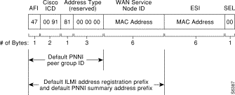
The 13-octet prefix of the PNNI Node ATM Address is used for the default UNI port prefix. All BPX Service Nodes use the first 7 bytes of this prefix (0x47 0091 8100 0000), the default PNNI peer group ID. The default PNNI Node ATM address is also used to form the PNNI Node ID as described in the section on Node ID.
An ATM address prefix may be configured for each BPX Service Node. The prefix is unique for each BPX Service Node in the network. ATM end point addresses (UNI ports) or host addresses attached to the BPX Service Node will usually bear this prefix. The default ATM UNI port address prefix, which is 104 bits long and configurable, is shown in Figure 4-4.

This prefix includes the 7 byte PNNI peer group ID (0x47 0091 8100 0000), plus a unique 6 byte MAC address. This is the prefix used for ATM ILMI address registration with ATM UNI ports.
Each BPX Service Node is associated with a specific ATM end point address termed the node ID. A node ID consists of 22 bytes, including the BPX Service Node's 20-byte default ATM address described in the section, End System Address, and with two prepended bytes. The first prepended byte corresponds to the PNNI level indicator byte (56 in this release, which is 38 hex). The second prepended byte is decimal 160 (A0 hex). When the default Node ID is not used, the reminder of the node ID address may be configured independently.
The Node ID is used as the source address within PNNI messages.The node ID of a BPX Service Node will not be allowed to be changed while the node is operational. For Node ID, the port field will be 0.
PNNI allows summarization of multiple ATM addresses into a single summary address prefix. Address summarization and the hierarchical organization of the topology enables PNNI to scale to very large networks.
Reachability information is used as the first step in routing a PNNI signaling request for a virtual connection. The Call Setup packet will be directed to a BPX Service Node advertising a prefix which matches the leading portion of the destination address. The longest matching reachable prefix is always used.
Host IDs are associated with the UNI ports of the BPX Service Node. A host ID usually consists of the prefix value that has been established for the BPX Service Node. In this case the remainder of the host ID will be determined through ILMI address registration procedure. Host IDs determined through the ILMI address registration procedure will be known to the PNNI element.
A BPX Service Node may consist of many ATM end point addresses. It may be desirable to reduce the amount of addressing information which needs to be distributed in a network. A summary address may be used for the purpose of optimizing the amount of messages. Summary addresses are configurable at each BPX Service Node. A summary address is a collective representation of multiple ATM end point addresses sharing a prefix. Each BPX Service Node has a default summary address which is equivalent to its address prefix. Individual addresses will be summarized. An override may be established through a manual configuration.
This information group describes internal reachable ATM destinations. Internal means known to PNNI to be local. For a node representing a single switch, an internally reachable address represents a summary of end systems (ATM or Frame Relay CPE) attached to the BPX Service Node, for example discovered ILMI address registration. Internal reachable ATM addresses can also summarize information provided by members of the same peer group.
Exterior reachable addresses may be configured at the PNNI element. A NSAP address format may be used for an exterior reachable entity. Addresses belonging to other independent PNNI domains are established using this mechanism. Manual configuration commands are available to establish external reachable addresses. PNNI protocol will not run over logical links that reach outside the PNNI domain.
A trunk on the BPX Service Node appears to the PNNI process as a logical link. In a single peer group a physical link connecting two BPX Service Nodes corresponds to a logical link. 256 logical links may be defined per ESP. The PNNI process utilizes an ATM/PVC socket to communicate over a logical link. VPI=0 and VCI=18 will be reserved for use by PNNI on each logical link.
The PNNI Hello protocol is used to track the operational status of a logical link. The operational status reflects the reachability of the neighbor attached to a logical link. The logical link's operational status may also change due to a failure at the physical layer. A physical layer failure may be trunk failure on a BPX switch. Upcd and Dncd commands issued on BPX switches will result in change of operational status as well. A failed or downed trunk appears as a deleted trunk for PNNI.
Every logical link has a dedicated set of resources for use by SVCs. The Maximum Cell Rate bandwidth (MaxCR) will be applicable to all service classes. MaxCR will be configurable per logical link and is the partition size for SVCs for a logical link. Available Cell Rate (AvCR) changes due to the addition or a deletion of an SVC. A significant change in AvCR will trigger the PNNI element to flood the network.
There are a limited number of connection channels per BSN port. A trunk may have sufficient capacity to support a given QoS with respective to the other metrics but it may still be limited from carrying more connections beyond its channel capacity limit. The free channel capacity must be tracked as an additional resource. If number of local resources like LCNs become zero, then ESP will inform the PNNI process that the AvCR for this link is 0.
The BPX will detect link-state changes at the physical layer and will pass them along to the PNNI protocol entity.
The PTSEs on a given BPX Service Node are used to calculate the PNNI routing tables. Route calculation is a background activity. This is a CPU intensive activity. Route calculation is triggered by a PTSE flood.
The Routing can be based on Cost or Delay. This is a configurable parameter by the network administrator. If Cost Based Routing is selected, then the routing decisions are based on Administrative Weight, otherwise they are based on delay. Default for routing procedure is Delay Based.
Four Route Tables will be derived out of the route calculation procedure irrespective of the Routing Policy. They are based upon a single optimization parameter, each with different constraints. The optimization parameter will be a function of MaxCR and the number of hops for Delay Based Routing Policy. The constraint parameter will be AvCR. Values for AvCR brackets will not be configurable. The default bracket values are (a)less than 100k, (b) greater than 100K, (c) greater than 1M, and (d) greater than 10M. For Cost Based Routing Policy, AW will be the optimization parameter.
An originating BPX Service Node will look up the routing tables to determine the DTL for an SVC. For a DACS (that is, local) connection, the call to the Route Agent will just return the egress port. Via nodes will not call the Route Agent. They will just advance the DTL pointer. This is the responsibility of ESP call processor function. At the far-end BPX Service Node of the connection, the Route Agent provides the egress port.
The BPX Service Node provides Load Balancing so that load gets distributed equally across all trunks. The second request to the Route Agent has the node and/or links specified that need to be excluded.
The PNNI entity maintains statistical counts for the normal and error activities at the packet layer, at the PTSE layer for advertisements, for the PTSE age out discards, for the PTSE flood procedures, for route table calculations and for route table look-up activities.
The PNNI process initializes its local node information from disk storage. It derives the remote node information through flooding. Therefore, when a standby ESP takes over, the PNNI information takes some time to be gathered from the network. During this period, all calls to the Route Agent will return `No Route Available'. PNNI is transparent to the other redundancy aspects of the BPX Service Node such as a BPX switch trunk card switchover, a BCC switchover and a UNI card switchover. The System Manager of the ESP performs any redundancy related mapping between logical ports and physical resources of the node.
The following PNNI parameters are provisioned through the ESP Configuration Interface:
The following PNNI parameters are provisioned on a per-port basis:
The use of the ESP Configuration Interface is described in Chapters 7 and 8.
IISP allows you to connect to networks that do not support PNNI.
IISP links are Network to Network Interface (NNI) trunks between BPX Service Nodes. Each link will be provisioned for:
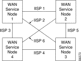
To be fully reliable, an IISP network composed of BPX Service Nodes would need to have full-mesh of IISP links. Obviously, this becomes impractical for a network of more than a few nodes. Figure 4-5 illustrates a simple IISP network with four BPX Service Nodes. Each BPX Service Node has three IISP links, one to each of the other three other BPX Service Nodes.
A BPX Service Node may be configured to have both PNNI and IISP links. A BPX Service Node having both PNNI and IISP links is effectively a PNNI border node for the PNNI group. The IISP static routes at the border node are PNNI external reachable addresses. When IISP static routes are configured on an IISP port, the ESP system manager sends them as external reachable addresses to the PNNI protocol entity. The PNNI protocol entity advertises them to other PNNI nodes if they do not match any summary addresses. These IISP static route addresses are included in the routing tables maintained by the PNNI Route Agent.
Consider an IISP-based network attached to a PNNI-based network, as shown in Figure 4-6. The PNNI border node is configured with a set of static routes that represent reachable end-points in the IISP network. These routes are broadcast to all nodes in the PNNI network.

Figure 4-7 illustrates a typical use of IISP.

A call originating in the PNNI network, for instance from CPE 2, can place a call to one of these IISP addresses. At the originating PNNI node, a DTL (designated transit list) is created representing PNNI nodes from the originating PNNI node to the border node. The Setup message traverses the PNNI network using the DTL list. When the Setup message reaches the border node, the Route Agent supplies the egress port, which is an IISP port. The IISP Setup message without the DTL list now traverses the IISP network using static routes configured at each node until it reaches the destination UNI, such as CPE 1.
A call originating in the IISP network, from CPE 1, can place a call to one of its statically configured routes which may be a destination address in the PNNI network. The IISP Setup message traverses the IISP network using static routes configured at each node until it reached the PNNI border node. At the entry border node a DTL list is created representing PNNI nodes from the entry border node to the terminating node. The Setup message traverses the PNNI network using the DTL list. When the Setup message reaches the terminating node, the Route Agent supplies the egress port which is the UNI port to the destination, CPE 2.
The BPX BPX Service Node uses PNNI to provide SVC routes even though IISP may be the routing protocol. This is done by registering all NNI addresses as External Reachable Addresses to PNNI. The Route Agent on the ESP provides the path for SVC calls based on this registration.
For IISP routing, the Route Agent at every node along the path provides the outgoing trunk. For PNNI routing, the Route agent provides the DTL list at the source node and provides the egress UNI port at the destination node.
A hybrid IISP and PNNI network can lead to certain problems that Network Administrators should be aware of. Hybrid PNNI and IISP networks must be designed with some caution. This problem can be easily seen when there are parallel paths to reach to the same destination through different protocols. As shown in Figure 4-8, from node A, you can get to node B via IISP or you can get to node B via PNNI through node C.
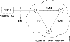
As shown in Figure 4-8, CPE 1, which is attached to node A, has an ATM address of "xyz." The address "xyz" is added to node A's local reachable address table when the UNI port is configured. It is also added to node B's local reachable address table when IISP is configured. In this network setup, we will find duplicated address "xyz" in node C's reachable network address table. One address originated from node A and the other from node B. On node A, "xyz" appears both in local reachable address table (added through UNI port) and its network reachable address table (learned from PNNI advertisement). A similar result can be seen on node B.
This type of configuration must be avoided. In other words, you must never have parallel paths to an address, with one using IISP and the other using PNNI.
![]()
![]()
![]()
![]()
![]()
![]()
![]()
![]()
Posted: Fri Jan 19 20:19:24 PST 2001
All contents are Copyright © 1992--2001 Cisco Systems, Inc. All rights reserved.
Important Notices and Privacy Statement.