|
|

The Cisco StrataCom BPX Service Node is an integrated BPX switch, AXIS interface shelf, and Extended Services Processor (ESP) used to provide ATM and Frame Relay Switched Virtual Circuits (SVCs) across a Cisco StrataCom wide-area ATM network. Although enhanced for SVCs, the network created out of BPX Service Nodes also supports traditional ATM and Frame Relay permanent virtual circuits (PVCs), as illustrated in Figure 1-1. An additional feature of the BPX Service Node is its use of the Private Network to Network Interface (PNNI) routing protocol. Defined by the ATM Forum for ATM networks, PNNI provides a dynamic routing protocol, is responsive to changes in network resource availability, and will scale to large networks.
A BPX Service Node network provides network interworking between Frame Relay and ATM networks, but there is no service interworking between ATM and Frame Relay CPE SVCs. While Frame Relay SVCs will be connected across the Cisco StrataCom ATM network, they have to be terminated on another Frame Relay device. Similarly ATM SVCs are established only between ATM CPE, that is end users. BPX Service Node resources, such as port VPI range and bandwidth and trunk bandwidth, are partitioned between SVCs and PVCs. Resource partitioning provides a firewall between PVCs and SVCs so that misbehaving CPE (end users) or large call bursts do not affect the robustness and availability of PVC services.
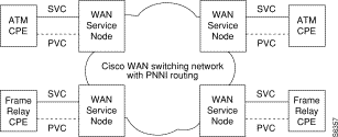
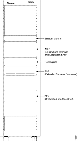
Figure 1-2 illustrates the BPX Service Node in a rack.
The BPX Service Node is an integrated BPX switch, AXIS interface shelf, and Extended Services Processor (ESP), supporting traditional wide-area PVC-based service, and providing new ATM and Frame Relay SVC-based services. As shown in Figure 1-3, the AXIS shelf and ESP are co-located with, and interfaced directly to, a BPX switch.
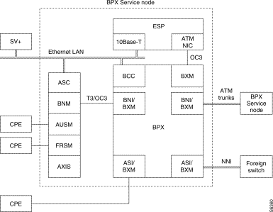
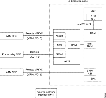
The AXIS shelf provides a service access platform for connecting a wide range of services over narrowband and medium-band interfaces to both ATM and Frame Relay customer premise equipment (CPE). ATM CPE is interfaced to the BPX Service Node through an AXIS ATM UNI Service Module (AUSM). Frame Relay CPE is interfaced to the BPX Service Node through an AXIS Frame Relay Service Module (FRSM). The AXIS maps all service traffic to and from ATM, based upon standardize interworking methods. The aggregated CPE service traffic is sent and received over an ATM interface to the BPX, an ATM switch, shown as the BNM-to-BNI/BXM T3/OC3 interface in Figure 1-3. The BPX is a Cisco StrataCom standards-based high-capacity (19.2 Gigabit) broadband ATM switch that provides backbone ATM switching and delivery of a range of user services. Note that as shown in Figure 1-3, the BPX switch can also provide an ATM service interface (shown as the ASI/BXM to CPE) for higher speed ATM CPE. The BPX switch also provides the high-speed (T3/E3 and OC3) ATM trunks to other BPX Service Nodes or the network-to-network interface (NNI) to standards-based foreign ATM switches. The ESP provides the BPX Service Node with the ATM or Frame Relay signaling function. It interprets industry-standard signaling messages from ATM or Frame Relay CPE to provide the call setup and teardown for switched virtual circuits across the ATM network. In addition to SVC signaling, the ESP also performs PNNI routing, collects statistics, and processes alarms and billing records for the BPX Service Node.
The AXIS Interface Shelf is described in detail in the Cisco StrataCom AXIS Reference and AXIS Command Supplement.The BPX switch is described in detail in the Cisco StrataCom BPX Reference and BPX Installation manuals. The Cisco StrataCom System Overview (formerly known as the StrataCom System Manual) provides conceptual information and describes the services and overall features of Cisco StrataCom wide-area networks.
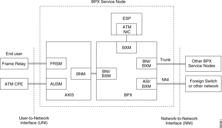
From the BPX Service Node's viewpoint, there are two types of external interfaces as shown in Figure 1-4:
Interim Inter-switch Protocol (IISP) is a static routing protocol defined by the ATM Forum to provide base level capability until the Private Network to Network Interface (PNNI) was specified. The IISP provides users with some level of multi-vendor switch interoperability based on the existing ATM Forum UNI 3.1 specifications. IISP assumes no exchange of routing information between switching systems. It uses a a fixed routing algorithm with static routes. Routing is done on a hop-by-hop basis by making a best match of the destination address in the call setup with address entries in the next hop routing table at a given switching system. Entries in the next hop routing table are configured by the user. IISP is described in more detail in Chapter 4.
Private Network to Network Interface (also known as Private Network to Node Interface) PNNI is a dynamic routing protocol defined by the ATM Forum. PNNI is a protocol specified for use between private ATM switches (for example, Cisco StrataCom BPX Service Nodes), and between groups of private ATM switches. PNNI includes two categories of protocols:
PNNI is described in more detail in Chapter 4.
To support ATM and Frame Relay SVCs, the Cisco StrataCom BPX Service Nodes essentially overlay a signaling network over a traditional (PVC-based) network. This signaling network, indicated by the dashed lines in Figure 1-5, connects all of the BPX Service Nodes and extends to the CPE. The signaling plane establishes and maintains SVCs between the CPE, that is, end users, across a Cisco StrataCom wide-area ATM network.
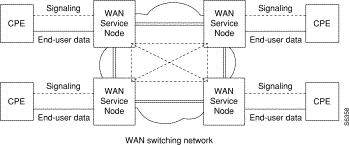
The signaling plane is created out of two basic types of signaling channels:
The signaling VCCs are normally configured during the provisioning of UNI ports and NNI trunks.
There is an internal signaling VCC established between every UNI port on the BPX Service Node which will support ATM or Frame Relay SVCs and the ESP in the BPX Service Node.There are two types of UNI signaling channels supported by the BPX Service Node as shown in Figure 1-6.
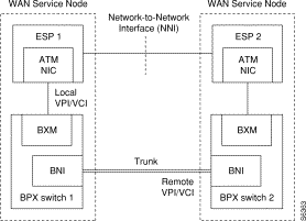
There is also a signaling channel established between each adjacent pair of BPX Service Nodes. This NNI signaling channel shown in Figure 1-7 is configured for either IISP or PNNI protocol. During IISP configuration, one side of the NNI signaling connection is configured as the user side and a weight is assigned. In the figure, the striped line indicates the logical connection; the physical connection is configured through BPX 1 and BPX 2.
The growing need for higher speeds, more bandwidth, and a wide variety of voice and data services is transforming communications networks. Fast packet networking, known technically as cell relay or asynchronous transfer mode (ATM), is becoming the dominant switching technology underlying high-speed communications in LANs, private WANs, and public networks. ATM provides high transmission speeds, low delay, and efficient use of bandwidth.
ATM is a telecommunications concept defined by ANSI and ITU (formerly CCITT) standards for carrying a complete range of user traffic, including voice, data, and video. In ATM, information is packaged into 53-byte cells, of which 5 bytes are used for header information. The 53-byte fixed-length cell was chosen to provide effective performance for all types of traffic. Being well-defined by the various standards committees, ATM has been chosen to be the underlying transport mechanism of the Broadband Integrated Services Digital Network (B-ISDN). (Transport refers to the use of ATM switching and multiplexing techniques at the data-link layer [layer 2 of the OSI model] to convey user information from source to destination within a network.)
While B-ISDN is a definition for public networks, ATM can also be used within private networks.
The ATM standards define a delineation between the transport layer and the application layer. ATM protocol is independent of the transmission speed of the connection. Unlike most LAN protocols, ATM is connection-oriented. Before data transfer can occur, an end-to-end connection must be established. Once a connection is defined, ATM cells are self-routing in that each call contains a header with an address that indicates its destination. This saves processing time at intermediate nodes within the network, since routing is pre-determined.
Each ATM cell header contains two address fields, a Virtual Path Identifier (VPI) and a Virtual Connection Identifier (VCI). These two fields identify each connection across a single link in the network. ATM switches use either the VPI alone or the VPI and VCI fields to switch cells from the input port to an output port at each network node. In ATM terminology, a VPC is a Virtual Path Connection, and a VCC is a Virtual Channel Connection.
The Cisco StrataCom System Overview contains further information about traditional Cisco StrataCom ATM networks, including conceptual information about ATM connections.
ATM and Frame Relay standards groups have clearly defined permanent virtual circuits (PVCs). After being added to the network, PVCs remain relatively static. A virtual circuit only allocates a physical connection when there's data to send. The connection between two devices is set up at the start of transmission, or when the network is configured. A PVC is similar to a dedicated private line because the connection is set up on a permanent basis. While no bandwidth is allocated on a PVC link when setting up the connection, the operator will tell the network about the characteristics of the desired circuit and sufficient network bandwidth is reserved.
With a switched virtual circuit, there must be some signaling mechanism to build a connection each time the user (ATM or Frame Relay CPE device) needs it. In addition, when the call is disconnected, there must be a mechanism for the orderly disconnection of the call, and the network's resources must be relinquished. During a disconnect, the Cisco StrataCom network sweeps through its connection tables and removes the connection.
Chapter 2 contains more detailed information about ATM SVCs.
Chapter 3 contains more detailed information about Frame Relay SVCs.
Because the BPX is an ATM switch, Frame Relay SVCs that are setup and established across the Cisco StrataCom network must be translated into an ATM format to be carried across the network. At the far end, where typically the connection is terminated on another Frame Relay CPE, the ATM cells have to be converted back to Frame Relay format. This is referred to as Network Interworking. Network Interworking can be performed between Frame Relay CPE and ATM CPE when the ATM CPE recognizes that it is connected to an interworking function (Frame Relay, in this case). The ATM CPE must then exercise the appropriate service specific convergence sublayer (SSCS). The SSCS will then convert the ATM cells to Frame Relay traffic.
In this release of the BPX Service Node, all Frame Relay SVC connections must be between Frame Relay CPE (Frame Relay end users) or ATM CPE that is aware that it is performing Network Interworking, and all ATM SVC connections must be between ATM CPE (ATM end users). In other words, Service Interworking between ATM and Frame Relay SVCs is not supported in this release. (ATM and Frame Relay Service Interworking for PVCs is supported by the BPX Service Node as part of Release 8.4.)
As described earlier, the Cisco StrataCom BPX Service Node is composed of an integrated BPX, AXIS, and ESP.
The Cisco StrataCom BPX switch is described in detail in the Cisco StrataCom BPX Installation Manual and the BPX Reference.
The BPX Service Node supports SVCs on the BPX cards listed in Table 1-1. (Note that the only the front cards are listed here and they must be mated with the appropriate backcard.)
| Model Number | Interface |
|---|---|
BXM-155-8 | OC3/STM-1 |
BXM-155-4 | OC3/STM-1 |
BXM-T3-8 | T3 |
BXM-E3-8 | E3 |
BXM-T3-12 | T3 |
BXM-E3-12 | E3 |
BXM-T3-4 | T3 |
BXM-E3-4 | T3 |
BXM-T3-12E | T3 |
BXM-E3-12E | E3 |
BXM-155-8E | OC3/STM-1 |
BXM-155-4E | OC3/STM-1 |
BXM-622-2E | OC12/STM-4 |
BXM-622E | OC12/STM-4 |
ASI-155 | OC3-STM-1 |
ASI-155-E | OC3-STM-1 |
ASI-T3 | T3 |
ASI-E3 | E3 |
BNI-155 | OC3-STM1 |
BNI-155E | OC3/STM-1 |
BNI-T3 | T3 |
BNI-E3 | E3 |
The Cisco StrataCom AXIS is described in detail in the Cisco StrataCom AXIS Reference and the Cisco StrataCom AXIS Command Supplement.
The BPX Service Node supports SVCs on the AXIS cards listed in Table 1-2. (Note that the only the front cards are listed here and they must be mated with the appropriate backcard.)
| Model Number | Interface |
|---|---|
AX-BNM-155 | OC3/STM-1 |
AS-BNM-DS3 | T3 |
AX-FRSM-4T1 | T1 |
AX-FRSM-4E1 | E1 |
AS-AUSM-8E1 | E1 |
AX-AUSM-8T1 | T1 |
The Extended Services Processor (ESP) is an adjunct processor shelf integrated into the BPX Service Node.
The basic ESP features include:
Available in either AC- or DC-powered models (ESP-AC or ESP-DC), the ESP is an orderable option for the BPX switch. The ESP can be configured in both non-redundant and redundant configurations. For the redundant configuration, two ESPs are installed in the BPX Service Node.
The ESP uses three main physical interfaces, as shown in Figure 1-8:
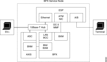
The ESP also provides the following application interfaces:
The ESP software includes the following components:
The BPX Service Node is typically configured through three Configuration Interfaces:
As shown in Figure 1-9, ESPs can be installed in redundant pairs in the BPX Service Node. In a redundant pair, one ESP is active, that is it controls the switched services in the BPX Service Node, and the other ESP is standby. The redundant ESPs are known as peers. The ESPs will switch roles from active to standby and vice versa under the following conditions:
Each ESP determines its role by means of Role Resolution protocol, which exchanges messages between the two units at startup. Both the active ESP and the standby ESP monitor its role and connectivity, and if appropriate, automatically switchover (that is, switch roles from active to Out of Service and from standby to active) with the peer ESP.
The redundant ESPs need to synchronize their database so that when the active ESP has gone out of service, the standby unit can take over and resume the service. There are two types of update mechanisms for synchronizing ESP databases. These are the bulk and real-time updates. The bulk update is used to synchronize a standby ESP with an active unit whenever it is restarted. The real-time updates are those messages that are exchanged after ESPs are synchronized and while both the active and standby ESPs are communicating.
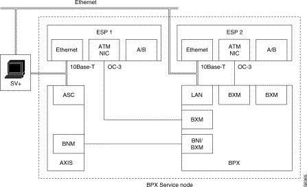
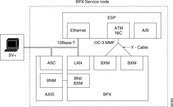
The BPX Service Node provides another form of ESP redundancy protection through the use of Y-cables. With Y-cables, the ESP ATM NIC can be connected to two BXM cards or two BXM ports, as shown in Figure 1-10. This prevents the failure of a BXM card or port from disabling the ESP. Appendix B, Cable Information, provides information about the various fiber optic cable assemblies available from Cisco StrataCom for the ESP.
As shown in Figure 1-3, the BPX Service Node could have an Ethernet LAN connection to a StrataView Plus Workstation. StrataView Plus discovers and monitors the ESP similarly to the way it does an AXIS interface shelf. StrataView Plus discovers the existence of the ESP when it is added to the BPX shelf with the addshelf command. After discovery, the ESP will be displayed on the StrataView Plus topology map as a shelf attached to the BPX switch.
StrataView Plus manages the BPX Service Node by providing:
In addition, StrataView Plus processes and logs the following traps reported by the ESP:
Active and Standby ESPs are viewed as separate entities. Alarms are supported by the Cisco StrataCom Robust Trap Mechanism (RTM) using the SNMP Agent and the RTM MIB. StrataView Plus uses the RTM's keep-alive protocol to decide whether the ESP is reachable. Unreachable status will be propagated to both the StrataView Plus map and database. All ESP traps will be logged into the StrataView Plus event log and also forwarded to any manager registered to receive traps from StrataView Plus. Up to 8 Trap managers can be supported.
Before the BPX Service Node network can provide ATM or Frame Relay SVCs in response to a call from the CPE, the individual ESP Server Shelves must be both configured and provisioned. Although the distinction is not necessarily sharp, in this manual, configuration will refer to setting up the BPX Service Node for operation, such as configuring the line between the ESP ATM NIC and the BPX BXM card, and provisioning refers to allocating resources for end-user PVC or SVC connections. Provisioning is done primarily, but not exclusively, with the ESP Configuration Interface.
ESP configuration and provisioning includes:
Most of the BPX Service Node provisioning is done with the ESP Configuration Interface, which is described in detail in Chapter 7. Chapter 8 contains provisioning procedures.
During provisioning, resources on all UNI ports (both ATM and Frame Relay) are partitioned between SVCs and PVCs. Partitioning is performed with the BPX and AXIS command line interfaces. Partitioning information is retrieved from the BPX by reading the port and trunk tables in the BPX switch MIB and from AXIS by reading the resource partitioning tables in the AUSM and FRSM MIBs.
The BPX line and routing or feeder trunk resources to be partitioned are:
AXIS Feeder Trunk (BXM/BNI) resources partitioned are:
AXIS AUSM port resources partitioned are:
AXIS FRSM port resources partitioned are:
SVCs are excluded from any PVC management operations such as OAM, ATM-LMI (Annex G), Frame Relay LMI and ILMI. SVC status is not reported by any of these protocols and an SVC failure does not generate any OAM AIS flows.
Procedures for resource partitioning are provided in Chapter 8.
The BPX Service Node collects and stores usage information on a per-call basis. This point-to-point billing information can be used by customers, such as the service provider with a network of BPX Service Nodes, as the basis for billing its end customers.
Currently, the BPX Service Node stores the billing records in a binary file. This binary file can be converted to a flat file (ASCII format) with the tool described in Appendix C in the section Billing Tools.
The BPX Service Node collects the following billing data:
Only BXM, AUSM, and FRSM SVC connections keep cell and frame counts. The ASI and BNI cards do not keep cell counts.
Billing and Call Detail Records are described in detail in Appendix C.
If you are a network administrator and need personal technical assistance with a Cisco product that is under warranty or covered by a maintenance contract, contact Cisco's Technical Assistance Center (TAC) at 800 553-2447, 408 526-7209, or tac@cisco.com. To obtain general information about Cisco Systems, Cisco products, or upgrades, contact 800 553-6387, 408 526-7208, or cs-rep@cisco.com.
Cisco StrataCom recommends that a modem be attached to the ESP to provide remote access for our Customer Service and Technical Assistance Center (TAC). With an attached dial-in modem, Customer Service can log in remotely and resolve potential problems.
Modem or telnet access are required during field trials of the BPX Service Node. There will have to be a modem attached (or telnet access provided) to every ESP in your network.
You can order the following modem through Cisco StrataCom:
Modem Part Number: IPX-5941B
Description: IPX ISC V.34RQ Modem 28.8, Sync, Async, with Security
Appendix G provides additional information about connecting a modem to the ESP.
![]()
![]()
![]()
![]()
![]()
![]()
![]()
![]()
Posted: Fri Jan 19 20:21:00 PST 2001
All contents are Copyright © 1992--2001 Cisco Systems, Inc. All rights reserved.
Important Notices and Privacy Statement.