|
|

Table Of Contents
In Line Voice Fax Card (VFC-01)
In Line Voice Fax Card (VFC-03)
Frame Relay Access Module (FRAM-01)
FRAM-01 Interface Adaptor Card
Grounding Considerations in E&M Applications
PTT/Telco Connectors and Cabling
Expansion Modules
Overview
Installing an expansion module in the FastPAD is described at the end of this chapter. The preceding sections describe installation considerations such as switch settings for each module.
The expansion modules shown in can be installed in the FastPAD expansion slots.
Table 7-1 Expansion Modules
VFC-01
8-16 kbps In-Line Voice/Fax Card
VFC-03
4.8-16 kbps Voice/Fax Card
FRAM-01
Frame Relay Access Module
The Voice/Fax expansion modules support a single Voice/Fax path between the FastPAD and an attached device.
Each FRAM-01 module provides three high-speed (up to 512 kbps) data channels. The following paragraphs describes each of the expansion modules that can be installed in a FastPAD.
Note
VFC-01 and VFC-03 expansion modules can be installed in the same FastPAD. However, the VFC-01 and VFC-03 can communicate only with the 16K ATC voice algorithm
In Line Voice Fax Card (VFC-01)
The VFC-01 Voice Fax Card plugs into any expansion card slot in a FastPAD and allows transmission of either voice or Group III fax over the private network. Each VFC-01 occupies one card slot; the FastPAD can support up to eight VFC-01 cards.
The VFC-01 connects with a single voice or fax source, via the RJ11 connector (FXS or FXO), or the RJ45 connector (E&M). When the local VFC-01 detects an off hook condition, a call is initiated. Once connected, the call is in voice mode.
The VFC-01 listens for fax tones from the answering fax machine. The answering fax machine provides a 2100 Hz tone which provides Called Station Identification. Alternately, the answering fax machine may send a 300 bps modem signal for Digital Signal Identification. Both signals originate at the called fax and describe the fax machine's capabilities to the calling fax machine. When either signal is received by the VFC-01, it will switch from voice to fax operation and continue with the fax protocol connection sequence.
If no fax tones are detected, the call remains in voice mode. When an on-hook condition is detected, the call is terminated and the VFC-01 returns to idle mode.
VFC-01 Hardware
The VFC-01 may be installed in any of the eight FastPAD expansion slots. The VFC-01 has both an RJ45 connector for interfacing with E&M (PBX multi-wire) circuits and an RJ11 connector for interfacing with FXS or FXO (two-wire) circuits.
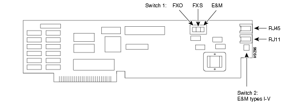
Figure 7-1 VFC-01 Card
Switch Settings
Switch 1: selects FXO, FXS or E&M signalling.
Note
Switch 2: Selects E&M types I-V
W4 position 1 selects 600 ohm impedance (suitable for FXS and E&M).
W4 position 3 selects complex line impedance (suitable for FXS).
Usually, either position will provide acceptable performance. However, if excessive echoing is experienced, moving the jumper should help to alleviate the problem. No other jumpers are user configurable.
Further configuration of the VFC-01 is described in Chapter 10.
In Line Voice Fax Card (VFC-03)
The VFC-03 operates identically to the VFC-01 described above. The difference between the VFC-01 and VFC-03 are:
•
•
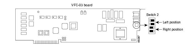
Figure 7-2 VFC-03 Switch 2: E&M Signalling Type Selection
Table 7-2 Switch 2
I
RIGHT
RIGHT
LEFT
LEFT
II
LEFT
RIGHT
RIGHT
LEFT
III
RIGHT
RIGHT
RIGHT
LEFT
IV
LEFT
RIGHT
RIGHT
LEFT
V
RIGHT
LEFT
RIGHT
RIGHT
E&M Signalling Type Settings
LEFT/RIGHT positions are left or right facing the back of the unit where the switch is visible through the connector edge of the card.
Software configuration of the VFC-03 is described in Chapter 11.
VFC-03 Hardware
The VFC-03 may be installed in any of the eight FastPAD expansion slots. The VFC-03 has both an RJ45 connector for interfacing with E&M (PBX multi-wire) circuits and an RJ11 connector for interfacing with FXS or FXO (two-wire) circuits.
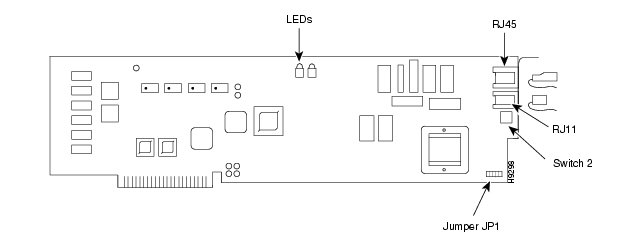
Figure 7-3 VFC-03 Board
Jumper Settings
Jumper JP1 selects 600 ohm, 800 ohm, or complex impedence:
•
•
•
•
600 ohm impedance is normally used for FXS and E&M applications. Complex line impedance is normally used for FXO applications that connect to a PSTN. Usually, either position will provide acceptable performance. However, if excessive echoing is experienced, moving the jumper should help to alleviate the problem.
Two LEDs are located on the upper edge of the board. These LEDs have different meanings depending on the telephony interface configured under software control. When the card is configured for E&M operation, the red LED indicates the presence of the "M" lead when it is ON. The green LED indicates the presence of the "E" lead when it is ON. If the card is configured for FXS or FXO operating mode, the red LED (ON) indicates an off-hook condition at the local FastPAD. When the green LED is ON, it indicates a connection is established.
The rear of the VFC-03 includes an RJ45 connector for interfacing with E&M (multi-wire) circuits and an RJ11 connector for interfacing with two-wire circuits.
The VFC-03 supports three voice compression algorithms:
•
•
•
Frame Relay Access Module (FRAM-01)
The FRAM-01 Frame Relay Access Module can be installed in any available FastPAD expansion slot.
Each FRAM-01 supports three high-speed (up to 512 kbps) synchronous data channels that operate in H/SDLC or Frame Relay modes. (Changing a data channel from H/SDLC to Frame Relay requires a reset.) Devices are attached to the FRAM-01 with a special 68-pin triplex cable that ends in three DB-25 male connectors. Each channel can be configured as:
•
•
•
Only one channel can be configured as a high-speed composite link. (StrataCom recommends channel 2). When configured as a data channel, a channel can have the same functionality as the base unit data channels except it can be configured for much higher data rates, or it can be configured for Frame Relay. Selecting a FRAM-01 channel as a high-speed composite link disables the standard base card composite link.
When a FRAM-01 data channel is configured as a Frame Relay Port with multiple PVCs, the channel functions as an integrated Frame Relay Switch that includes the following features:
•
•
•
•
•
When a frame relay switch port is configured active, it is assumed the composite link is connected to the integrated switch (i.e., no other base card or data card composite link can be configured).
Note
When a FRAM-01 data channel is configured as a frame relay switch port, data rates in the range 1.2K to 512 kbps can be selected.
FRAM-01 Hardware
A red LED is located just below the jumper labeled J2 on the upper edge of the FRAM-01. This is a hardware diagnostics LED that will flash momentarily at power on. During normal operations, this LED should be on solid. If this LED flashes continuously at any time after the power-up sequence, it indicates a hardware failure. If this is the case, call StrataCom Customer Support for assistance.
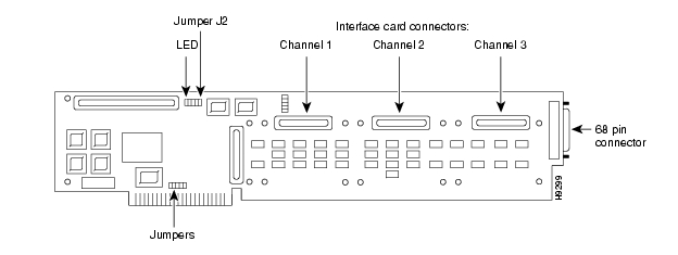
Figure 7-4 FRAM-01 Board
A 68-pin connector is located on the rear of the FRAM-01. This connector and the triplex cable (Part # 5050250-012) included with the card are used to attach either DTE or DCE devices to the FastPAD.
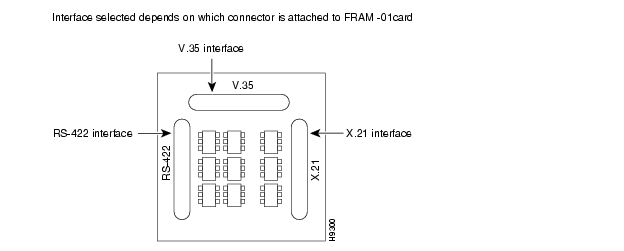
There are three connectors on the card that can be used to attach electrical interface adapters for each of the three data channels. The FRAM-01 interface adapter card converts the standard RS-232 interface for a selected data channel to V.35, V.11/X.21 or RS-449/422. The triplex cable provided with the card supports all three interfaces. There are three connectors on the interface adapter card that support each electrical interface: the electrical interface designations (V.35, RS422, and X.21) are silk-screened on the back of the card.
On the FRAM-01 data card, there are three connectors on the component side of the board (corresponding to the three data channels) where the interface adapter card can be installed. (See ) The connector closest to the J2 jumper and LED supports data channel 1. The connector in the middle supports data channel 2. The connector closest to the 68-pin connector supports data channel 3. To install an interface adapter card, simply choose the appropriate electrical interface connector (V.35, RS422, or X.21) on the interface adapter card and plug it into one of the data channel connectors on the FRAM-01 data card.
FRAM-01 Interface Adaptor Card
The default interface for each port is RS-232. The interface adaptor card enables each port to present an RS-422, V.35, or X.21 interface, as selected by the position of the interface adaptor card.
Figure 7-5 FRAM-01 Interface Card
FRAM-01 Jumpers
There are several jumpers on the FRAM-01 card. They are all set at the factory and cannot be changed.
Telephony Interface
Voice Fax Expansion Modules provide support for three different types of telephone interfaces: FXS, FXO and E&M.
FXS Connections
FXS is a two-wire telephone communication mode. In this mode, the Voice Fax Expansion Modules present a telco/PTT interface similar to a Central Office interface. When configured in this mode, a Voice Fax Expansion Module can interface to a conventional two-wire telephone (pulse-dial or touch-tone). A Voice Fax Expansion Module in FXS mode can also be connected to a two-wire CO trunk of a PBX or KSU. Additionally, in FXS mode, the Voice Fax Expansion Module provides loop current similar to a telephone company's Central Office. It also detects off-hook and on-hook states, and generates ring voltage.
FXO Connections
FXO is a two-wire telephone communication mode. In this mode, the VFC-01 or VFC-03 presents a telco/PTT interface which looks like a standard telephone set. The VFC card can be connected to analog station ports (extensions) of a PBX. The FXO option provides the appearance of a two-wire telephone in a loop-start circuit. An FXO-configured voice port on the VFC card detects ring voltage and closes the loop during off-hook and opens the loop in an on-hook condition.
When a Voice Fax Expansion Module is used in two-wire mode, set all four switch positions of the DIP switch pack (Switch 2) located on the rear Voice Fax Expansion Module to the UP position (away from board). This applies to both FXO or FXS operation.
Both loop-start and ground-start are supported via front panel configuration.
E&M Connections
E&M is a communication mode employed in PBX-to-PBX communications. This type of interface uses a two-wire or four-wire voice circuit plus up to four wires for E&M signalling.
PBX E&M tie-line connections usually require multi-conductor dedicated circuits to support full-duplex voice and separate signalling lines. Typically, eight wires are required: four for voice (two wires in each direction) and four for E&M signalling. Some PBXs use two wires (one pair) for bi-directional voice. Voice Fax Expansion Modules can interface with either type of circuit.
This section provides configuration information required to interconnect the port configured for E&M signalling with a corresponding PBX E&M tie line trunk. Appendix G, , provides additional information concerning E&M signalling types.
Note
Switch 1 on the VFC-01 card in the E&M position (toward the rear of the card), selects E&M signalling. E&M is software selectable from the front panel on VFC-03 boards. The DIP switch pack (Switch 2) on the rear of the Module must then be used to select the type of E&M signalling (I through V).
E&M signalling requires the use of the RJ45 connector. Both two-wire and four-wire E&M interfaces are supported; this selection is made via the front panel expansion channel configuration.
Table 7-3 E&M Signalling Types (Switch 2) Settings (facing rear of installed card)
I
Right
Right
Left
Left
II
Left
Right
Right
Left
III
Right
Right
Right
Left
IV
Left
Right
Right
Left
V
Down
Up
Down
Down
FXO
Left
Left
Left
Left
FXS
Left
Left
Left
Left
Follow this step-by-step check list when connecting the Voice Fax Expansion Module in an E&M application:
Step 1
Step 2
Step 3
Step 4
Note
Grounding Considerations in E&M Applications
Proper grounding is essential for correct operation of telephone equipment in E&M applications. E&M signalling works by applying DC voltages to the E and M leads in the process of connecting and disconnecting. Without a proper ground, the DC voltages do not have a common point of reference, which can result in unintended or sporadic signalling.
Notice the following possibilities:
1
2
Based on the above conditions, grounding may be established directly or indirectly. The direct method is to connect a grounding wire between the telco/PTT interfaces on the PBX and FastPAD. You can do this by connecting the ground wire from the PBX to pin 8 (SG) of the RJ45 connector on the Voice Fax Expansion Module. This will establish the same ground potential at both interfaces.
For various reasons, direct grounding is not always possible or practical. To establish an indirect ground, make sure the telco/PTT grounds of the PBX and the FastPAD are connected to their respective AC grounds. The AC grounds of the two devices must be at the same potential as is usually true when both devices are located in close proximity.
Check with the PBX manufacturer regarding connecting the PBX AC ground to telco/PTT ground. On the FastPAD, installing a jumper at W7 on the baseboard provides the connection between chassis ground (same potential as AC ground) and telco/PTT ground. A common telco/PTT ground will then be present for every expansion module installed in the FastPAD. Jumper location W7 can be found on the baseboard next to the power supply cage, near the front of the FastPAD.
Note
Interface Conversions
The FastPAD allows you to use a different telephony interface at either end of a voice/fax connection. Through system software, each Module is informed of the interface type used at the remote end. Signaling conversion is done in software without the aid of any external equipment.
Table 7-4 Analog Interface Network Conversion
Installation Instructions
Warning
The FastPAD must be unplugged from the AC power source before you remove the protective cover. Proper anti-static procedures must be followed.
A VFC expansion module can be installed in any available expansion slot in a FastPAD or FastPAD Micro. Complete the following steps to install a VFC expansion module:
Step 1
Step 2
Step 3
Step 4
Step 5
Step 6
Step 7
Step 8
Step 9
PTT/Telco Connectors and Cabling
The 8-wire RJ45 jack on a Voice Fax Expansion Module is mainly used for E&M operation.
Figure 7-6 RJ45 Connector Pins
An RJ45 cable is included with each Voice Fax Expansion Module. The cable end with the RJ45 connector plugs into the Module. The cable end with non terminated wire connects to a telco/PTT type spay lug block.
Table 7-5 RJ45 Cable Connections
The 6-wire RJ11 jack on the Voice Fax Expansion Module is connected in parallel with the RJ45 jack. However, the RJ11 only supports two pins: Tip (green) and Ring (red). A standard RJ11 two-wire cable is included for establishing two-wire connections.
Figure 7-7 RJ11 Connector Pins
The supplied RJ45 cable can also be used to provide the two-wire connection. For these applications, only the red and green wires are active; the other wires should be insulated with electrical tape to prevent unwanted interference.
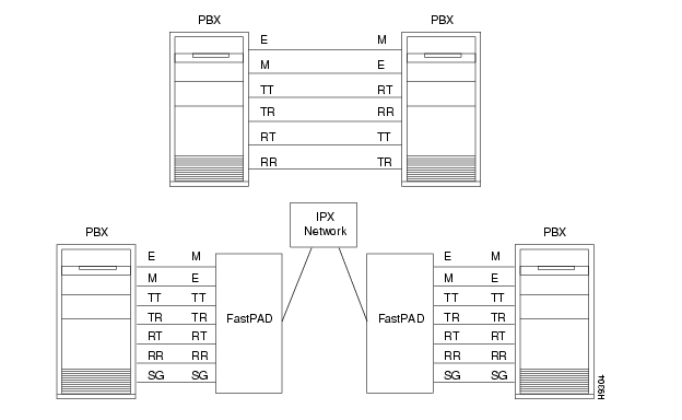
E&M Wiring
In a two-wire E&M application, connect Red and Green wires to the PBX's RT and RR pair, respectively. The RT and RR pair carry voice or fax analog signals between the Voice Fax Expansion Module and the PBX.
In a four-wire E&M application, connect Red and Green wires to the PBX's RT and RR pair, and Black and Yellow wires to the PBX's TR and TT pair, respectively. The RT and RR pair carry voice or fax analog signals from the Voice Fax Expansion Module to the PBX. The TR and TT pair carry voice or fax analog signals from the PBX E&M tie trunk to the Voice Fax Expansion Module. Connect the signalling wires as shown in .
Table 7-6 E&M Connections
Figure 7-8 Trunk and Station Connections
Figure 7-9 E&M Connections
![]()
![]()
![]()
![]()
![]()
![]()
![]()
![]()
Posted: Wed Aug 25 16:25:18 PDT 2004
All contents are Copyright © 1992--2004 Cisco Systems, Inc. All rights reserved.
Important Notices and Privacy Statement.