In asynchronous mode, the data channels default is 8 bits, no parity, and 1 stop bit. Since the 8th bit is considered data, 7 bits plus a parity bit is also passed through. Thus the following data formats are supported:
8 bit, no parity
7 bit, even parity
7 bit, odd parity
7 bit, space parity
7 bit, mark parity
The FastPAD does not check parity. All error detection must be handled by the attached devices.
In addition to the rates listed above, the High Speed data channel on the FastPAD can operate synchronously at the following rates:
28.8 kbps
32 kbps
38.4 kbps
48 kbps
56 kbps
64 kbps
At the higher rates, a V.11, V.35, or RS-449 interface adapter card is recommended to ensure error-free operation (See Chapter 5 for details). All synchronous data channels are clear, full duplex and independent of data protocol. Data rates are selected through software via the front panel LCD and push-button controls (see Chapter 9). Each provides a female DB25 connector with a DCE interface.
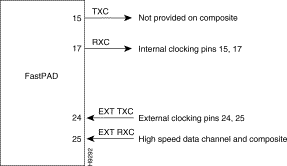
Data input and output to and from the FastPAD is accessed via 25 pin connectors for all data channels as well as the composite channel. Figure 6-1 identifies the pin assignments for the various timing signals.
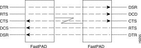
FastPAD data channels are DCE. Five control signals are associated with each data channel. Data Terminal Ready (DTR) and Request To Send (RTS) are both input signals from the attached device. Data Set Ready (DSR), Carrier Detect (CD), and Clear To Send (CTS) are output signals to the attached device. A FastPAD link crosses control signals similar to a crossover cable or null modem.
DTR (Input): Data Terminal Ready on each data channel can be optionally passed through to the remote end as DSR (Data Set Ready). ON/OFF transition of DSR may not coincide with a data boundary.
RTS (Input): Request to Send on each data channel can be optionally passed through to the remote end as CD (Carrier Detect). ON/OFF transition of CD may not coincide with a data boundary.
CTS (Output): Clear to Send on each data channel can be programmed to follow local RTS (Request to Send) with a configurable delay or it can configured as permanently ON or OFF.
DSR (Output): Data Set Ready on each data channel can be programmed to follow remote Data Terminal Ready (DTR). Optionally, DSR can be software configured as permanently ON or OFF.
CD (Output): Carrier Detect on each data channel can be programmed to follow remote Request To Send (RTS). Optionally, CD can be software configured as permanently ON or OFF.
To summarize, for each of the output control signals it is possible to software configure CTS, DSR and CD to a high, a low, or to follow the appropriate input control signal.
For data control signals, ON means the control signal is in a space condition (+12 Vdc). OFF refers to the mark condition (-12 Vdc). ±12 Vdc refers to average voltage levels for space and mark in RS-232.