|
|

The network processor manages the three interface levels (layers) between synchronous equipment and the public network. X.25 configuration is governed by the software license XPLS.
The levels/layers are defined in the ITU-T X.25 recommendations and in the OSI (Open System Interconnection) standard, issued by the ISO (International Standardization Organization).
These three levels/layers, managed by the FastPad equipment, are:
| Levels | Layers according to the ISO standard | X.25 ITU-T recommendations |
|---|---|---|
1 | Physical | Physical |
2 | Data-Link | Frame LAPB |
2 | Multi-Link | Multi-Link MLP |
3 | Network | Packet X.25 |
This level transmits series of bits over the physical interconnection medium.
This level is responsible for the error-free routing of data blocks over the physical line.
The operating principle of the frame level is in conformity with the LAP-B (Link Access Procedure-Balanced) modulo 8 and 128 procedure defined in the ITU-T. This procedure is equivalent to the "balanced" mode of the HDLC standard issued by the ISO, and like HDLC and supervisory, Information and Unnumbered Frame.
On this level, the network processor might be configured C12RxP1 in the following modes:
The frame level is established when the DTE-configured equipment sends an SABM frame and the DCE-configured equipment replies with a UA frame (SABM = Set Asynchronous Response Mode; UA = Unnumbered Acknowledge).
The FastPad equipment takes the initiative to
The local as well as the remote party of the FastPad equipment could take the initiative to connect or disconnect the frame level (as is the case in the DTE mode) by sending SABM or DISC.
The FastPad equipment does not take the initiative to connect or disconnect the frame level. It issues a DM (= Disconnect mode) to indicate that it requests a mode setting command. The response could be:
Whatever the type of connection (DTE, DCE or DSE), the FastPad equipment manages contention e.g. in case two SABM frames are sent, one by the DTE and one by the DCE equipment.
The multi-link procedure is defined in ITU-T norm X.25-84. Its function is to distribute the packets among the available lines, each line operating according to the single line procedure, and restore the sequence of the packets on the remote side for further transfer to the packet layer.
To enable an MLP line to be managed, the line must be configured as belonging to an MLP bundle of the processor of the FastPad network. Configuration of the MLP bundle takes place in class 25, recurrences 0 to 8. MLP configuration is governed by the software license XPLS, XMLP.
The lines that may be configured in a bundle are of the dedicated or switched type (PSTN or ISDN). A switched line may be assigned dynamically in a bundle on the initiative of the Network Management System, a telemaintenance center or on the basis of certain load or overflow criteria.
In the case of the ISDN, a line may be shared by several bundles. In fact, the checking of the caller is possible on integrated ISDN, contrary to the case of the PSTN.
Certain foreign ISDN networks do not send the original calling number. In this case, the ISDN line cannot be shared.
The multi-link level is established after the following procedure has been executed:
For more details on MLP, refer to the section "Backup/Overflow/Dynamic Line Management (DLM)" in Chapter 7.
This level assures the routing of the data packets across the network and flow control mechanism.
The signalling of the FastPad equipment is based on X.25 standards issued in 1984. It changes with national implementation. C12RxP2 is used for doing the adaptation.
Available facilities of the FastPad equipment are the following:
The response of the FastPad equipment to the facility markers mentioned in the X.25 standards can be configured (C12RxP83).
The FastPad equipment supports the PVC function, allowing data transmission between two subscribers at any time, without transmitting call request or clear packets (from a subscriber point of view). Data may be transmitted in full duplex.
 Diagram
On one FastPad node the PVC is configured as a calling PVC and on the other node as a called PVC.
A PVC is set up between a FastPad node and one or more subscribers.
At network level, the virtual circuits established are switched virtual circuits (SVCs).
A PVC may have two states:
These states are communicated to each device by means of reset packets.
Viewed from the FastPad equipment, set-up of a PVC is carried out in three phases:
These three phases are illustrated below
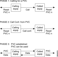 Diagram
The FastPad meets the requirements of the ITU-T X.25 recommendation. It offers three types of X.25 interfaces (see Figure 6-3, Figure 6-4 and Figure 6-5):
1. an interface with an X.25 subscriber,
2. an interface with a PSPDN public switch packet data network.
3. an interface to another FastPad.

The behavior of the FastPad in case of a protocol error depends on the type of interface. The selection of the type of interface is made in the configuration.
This interface is intended to connect X.25 subscribers to the FastPad. There are two profiles available:
Profile 1: | X.25 subscriber profile without additional services. |
Profile 2: | X.25 subscriber profile with additional services. |
 X.25 Subscriber Interface
Profile 1 offers the following services:
The call confirmation packet format and the reset sent by the FastPad are reduced (no address and no additional services).
Profile 2 has the following services available:
The call confirmation packet format and the reset sent by the FastPad are extended (additional services but no address service).
This interface gives the FastPad direct access to a public switched packet network or across a switched circuit network. Two profiles are available:
Profile 0: | Direct access connection to a public network with additional services; the throughput class and the packet window size are set to 2. |
Profile 3: | Direct access connection to a public network without additional services; the packet window size set to 3. |

These types of interfaces with a PDN (Public Data Network) need special address processing.
The public network considers the FastPad as the CPE of a private PDN. At the subscriptions X.121 address is assigned to the CPE by the carrier.
With the "Compacting/decompacting" tables in the FastPad, it is possible to translate a private network address (DNICZOAB) into a sub-address and vice versa.
To enable the FastPad to determine the position of the subscriber, the user must also supply the subscriber number on the public network.
So, when configuring the FastPad, the user must complete the compacting/decompacting tables (C11) and the PDN address table (C10).
The PDN address table gives information only about public networks where two addresses (called/calling) are used. The calling address then identifies the switch access point to the public network.
The numeration over the public network can be done by using:
The private network "calling" and "called" addresses are transported across the public network in the complementary address extension service using the DTE marker (see the X.25 recommendations).

The lines with the public data network must be configured with parameter 52 = 4.
Node Zl puts the private addresses in the extension address facility field and adds the DTE marker. If the marker already exists, the addresses are inserted after the marker.
To be able to reach subscriber B, the private address of DTE B is translated into a public address using the called address inversion table for outgoing calls. This address corresponds with the public address of the node.
On the outgoing side of the public network, node Z2 re-forms the calling and called addresses, using the extension address facility. When only the facilities with the DTE marker are transmitted, the marker is suppressed.
For the operator, this procedure is transparent and compatible with the subscriber's use of the DTE marker and address extension facilities, at least when the maximum facility field size of a call packet is respected (See ITU-T X.25 recommendations).
This interface is intended to connect two FastPads to each other, directly or via a modem.
When the FastPads are connected via modems, an automatic backup via the PSTN can be made (see Figure 6-7).
The internal protocol assures the continuation of the communication in progress during the switch- over to the PSTN and back.
Backup takes place transparently for the users of the network.
The Network Management System is informed of the switch-over to the PSTN by the reception of an outstanding event, CT117 closed (CT117 = standby indicator).
Switching back is indicated by the opening of the CT117 contacts.

There are four profiles available:
Profile 4: | Inter node line, receiving clock signals (RC), circuits 114/115. The primary address = 0l and the logical channels are scanned in decreasing order. |
Profile 5: | Inter node line, transmitting clock signals (TC), circuits 114/115. The primary address = 03 and the logical channels are scanned in increasing order. |
Profile 20: | Inter node line with automatic backup via PSTN. The primary address = O1 and the logical channels are scanned in decreasing order. |
Profile 21: | Inter node line with automatic backup via PSTN. The primary address = 03 and the logical channels are scanned in increasing order. |
The X.25 protocol used between the FastPad requires that certain Parameters (primary address, scanning direction of logical channels) are in reverse on both ends of one FastPad link. Profiles 4 and 5, 20 and 21 manage these reversals.
Class 1 R1: type of line |
|
| |
<port #> : 1 | X.25 |
|
|
|
|
|
|
Class 12 R <port#> |
|
| |
0 ? | X.25 |
| |
Physical level parameters |
|
| |
P20,21,24,25 P28 | Signals requested to be present to declare the line in service. Signals forced on the interface. Access rate |
| |
Frame Level: |
|
|
|
P1 P29 P32 P36 P37 P38 | Type of link N1, frame size T1, Time-out to receive an acknowledgment T2, Time-out to acknowledge a frame N2, retransmission counter K, frame window Modulo Primary @ Secondary @ | | 1 DTE, 2 DCE, 3 DSE up to 8KB (1-250)* 100ms 8 for 8, 128 for 128 1 DTE, 3 DCE 1 DCE, 3 DTE |
Packet Level: |
|
|
|
P3 P40 P41 P42 P45 | Logical Channel scanning direction Logical Channel organization T10, T20 restart timer T12, T22 reset timer T13, T23 clear timer Nbr of retry for P39,40,41 Diagnostic code suppression for P39,40,41 Signaling type Nbr of addresses in Call Request packet Subscriber number, significant if P44 = 1 Call Conf packet format | | 0 decreasing, 1 increasing
(1-250)* 10s (1-250)* 10s (1-250)* 10s 1-250 (0 X.25 NT, 1 X.25 TE, 2 X.75 1 or 2 0 F+@, 1 F, 2 nothing (1-250)* 10s 0 F+@, 1 F, 2 nothing |
| |||
| |||
| |||
Facilities: |
|
|
|
|
|
|
P48 | CUG, Closed User Group |
|
|
|
| |
P49 | RC, Reversed Charging |
|
|
|
| |
P54 | FS, | Fast Select |
|
| ||
P5 | Throughput negotiation |
|
|
|
| |
P57 | Def | Tx |
|
|
|
|
P58 | Def | Rx |
|
|
|
|
P59 | Max | Tx |
|
|
|
|
P60 | Max | Rx |
|
|
|
|
P61 | Packet negotiation |
| ||||
P62 | Def | Tx |
| 16B - 8KB |
|
|
P63 | Def | Rx |
|
|
|
|
P64 | Max | Tx |
|
|
|
|
P65 | Max | Rx |
|
|
|
|
P66 | Min | Tx |
|
|
|
|
P67 | Min | Rx |
|
|
|
|
P68 | W, window negotiation |
| 1-7 |
|
| |
P69 | Def | Tx |
|
|
|
|
P70 | Def | Rx |
|
|
|
|
P71 | Def | Tx |
|
|
|
|
P72 | Def | Rx |
|
| ||
P90 | Nbr of PVC |
|
| Up to 250 per equipment | ||
P91 | Entry index for the First PVC | |||||
Specific: |
|
|
|
|
|
|
P2 P52 P53 P81 P82 P83 P89 | Type of connection PDN link entry index in C10r0 Call return (trunk) Call return(subscriber) facility marker control @ conversion/aimed point | 08 Telenet, 12 Tymnet, 52 Uninet, 64 Itapac 0 no, 1 yes, 4, yes & @ transport to define the X.121 PDN @. Only if 45 = 2 | ||||
CATEGORY | COMMANDS | RESPONSES | CONTROL FIELD | HEX VALUE | ||||||||
I-FRAME | I |
| 7 r r r r 0 0 0 1 1 | 6 r r r r 0 1 1 0 0 | 5 r r r r 1 0 1 0 0 | 4 P/F P/F P/F P/F P P P 1 P | 3 s 0 0 1 1 1 1 1 1 | 2 s 0 1 0 1 1 0 0 1 | 1 s 0 0 0 1 1 1 1 1 | 0 0 1 1 1 1 1 1 1 1 | P/F = 1 even x1 1 x1 5 x1 9 1F 1F 1F 1F 1F | P/F = 0 even x2 1 x25 x2 9 1F 1F 1F 1F 1F |
S-FRAME | RR RNR REJ | RR RNR REJ | ||||||||||
U-FRAME | SABM DISC | DM UA FRMR | ||||||||||
r = receive counter 1 odd number
s = send counter 2 even number
P = poll bit
F = final bit
|
| 7 | 6 | 5 | 4 | 3 | 2 | 1 | 0 | BIT |
BYTE | 1 | GENERAL FORMAT ID | LOGICAL CH. GROUP NO. | |||||||
|
| Q | D | N | N |
|
|
|
|
|
| 2 | LOGICAL CHANNEL NUMBER |
| |||||||
| 3 | PACKET TYPE IDENTIFIER | ||||||||
| 4 | OTHER FIELDS
| ||||||||
|
| |||||||||
|
| |||||||||
| n | |||||||||
FROM DTE TO DCE | FROM DCE TO DTE | PACKET TYPE ID. (hexadecimal) |
Call set-up and clearing |
| |
Call Request Call accepted Clear request DTE Clear confirmation | Incoming call Call connected Clear indication DCE Clear confirmation | /0B /0F /13 /17 |
Data and interrupt |
| |
DTE data DTE interrupt DTE interrupt confirmation | DCE data DCE interrupt DCE interrupt confirmation | /even /23 /27 |
Flow control and reset |
| |
DTE RR (mod 8) DTE RR (mod 128) DTE RNR (mod 8) DTE RNR (mod 128) DTE REJ (mod 8) DTE REJ (mod 128) Reset request DTE reset confirmation | DCE RR (mod 8) DCE RR (mod 128) DCE RNR (mod 8) DCE RNR (mod 128)
Reset indication DCE reset confirmation | /x1 /01 /x5 /05 /x9 /09 /1B /1F |
Restart |
| |
Restart request DTE restart confirmation | Restart indication DCE restart confirmation | /FB /FF |
Diagnostic |
| |
| Diagnostic | /F1 |
Registration |
| |
Registration request |
Registration confirmation | /F3 /F7 |
 X.25 SVC Configuration
C1R1 ( type of the link) | C1R1 |
1 1 <trunk #> 1 | 1 1 <trunk #> 1 |
C1R1 ( type of the link) | C1R1 |
0 900000 | 0 800000 |
C12R1 (service parameters) | C12R1 |
0 1 ( X.25 DCE user profile) 1 2,0 (X.25 network) 2 5,11 (1st incoming Lcn) 3 9,1 (1st both ways Lcn) 4 11,10 (Nbr of bothways) 5 13,1 (1st outgoing Lcn) 6 28,10 (access rate 9600b/s) 7 32,30 (T1 = 3s) 8 33,10 (T2 = 1s) 9 35,7 (k = 7) 10 45,2 (mode 2 addresses) 11 48,0 (no CUG) 12 56,0 (no throughput neg) 13 74,0 (short call conf format)
default value 29,2 (frame size = 256B) 62,7 (Tx-packet size = 128) 63,7 (Rx-packet size = 128) 69,2 (Tx-window size = 2) 70,2 ( Rx-window size = 2) | 0 1 ( X.25 DCE user profile) 1 2,0 2 5,3 3 9,1 4 11,2 5 13,1 6 28,10 7 32,30 8 33,10 9 35,7 10 45,2 11 48,0 12 56,0 13 74,0
default value 29,2 (frame size = 256B) 62,7 (Tx-packet size = 128) 63,7 (Rx-packet size = 128) 69,2 (Tx-window size = 2) 70,2 ( Rx-window size = 2 |
C12R <trunk #> | C12R <trunk #> |
0 5 X.25 DCE trunk profile default value 11,20 (Nbr of bothways) 29,2 62,7 63,7 69,3 70,3 | 0 4 X.25 DTE trunk profile default value 11,20 (Nbr of bothways) 29,2 62,7 63,7 69,3 70,3 |

C1R1 ( type of the link) | C1R1 |
1 1 <trunk #> 1 | 1 1 <trunk #> |
C1R2 | C1R2 |
0 900000 | 0 800000 |
C12R1 (service parameters) | C12R1 |
0 1 ( X.25 DCE user profile) 1 2,0 (X.25 network) 2 5,13 (1st incoming Lcn) 3 9,3 (1st bothways Lcn) 4 11,10 (Nbr of bothways) 5 13,3 (1st outgoing Lcn) 6 28,10 (access rate 9600b/s) 7 32,30 (T1 = 3s) 8 33,10 (T2 = 1s) 9 35,7 (k = 7) 10 45,2 (mode 2 addresses) 11 48,0 (no CUG) 12 56,0 (no throughput neg) 13 74,0 (short call conf format) 14 90,2 (Nbr of PVC) 15 91,1 (1st entry in C17R0) | 0 1 ( X.25 DCE user profile) 1 2,0 2 5,4 3 9,2 4 11,2 5 13,2 6 28,10 7 32,30 8 33,10 9 35,7 10 45,2 11 48,0 12 56,0 13 74,0 14 90,1 15 91,1 |
C12R<trunk #> | C12R<trunk #> |
0 5 X.25 DCE trunk profile | 0 4 X.25 DTE trunk profile |
C17R0 | C17R0 |
0 0,1,1,1 0 not significant 1 called side 1 local Lcn number 1 remote Lcn number 1 0,1,2,2 0 not significant 1 called side 2 local Lcn number 2 remote Lcn number | 0 1,0,1,1 1 1st entry in C8 0 calling side 1 local Lcn number 1 remote Lcn number
|
C8R0 | C8R0 |
| 0 90001001 Called address |
C8R4 | C8R4 |
| 0 1 |
X.25 PSPDN configuration
X.121 address of the FastPad is 196810. The PSPDN works in two addresses.
 X.25 PSPDN Configuration
| C1R1 ( type of the link) | |
|---|---|
1 1 <trunk #> 1 |
|
| C1R2 | C2R2 |
0 800030 | 6 0 (insertion of the compacted Sub @) |
| C12R1 (service parameters) | C12R<trunk #> |
0 1 ( X.25 DCE user profile) 1 2,0 (X.25 network) 2 5,1 (1st incoming Lcn) 3 9,1 (1st bothways Lcn) 4 11,4 (Nbr of bothways) 5 13,5 (1st outgoing Lcn) 6 28,10 (access rate 9600b/s) 7 32,30 (T1 = 3s) 8 33,10 (T2 = 1s) 9 35,7 (k = 7) 10 45,2 (mode 2 addresses) 11 48,0 (no CUG) 12 49,0 ( no Reverse Charging) 13 54,0 ( no Fast Select) 14 56,0 (no throughput neg) 15 74,0 (short call conf format) 16 85,2 (short clear request format)
default value 29,2 (frame size = 256B) 62,7 (Tx-packet size = 128) 63,7 (Rx-packet size = 128) 69,2 (Tx-window size = 2) 70,2 ( Rx-window size = 2) | 0 1 ( X.25 DCE user profile) 1 2,0 2 5,3 3 9,1 4 11,2 5 13,1 6 28,10 7 32,30 8 33,10 9 35,7 10 45,2 11 48,0 12 56,0 13 74,0
default value 29,2 (frame size = 256B) 62,7 (Tx-packet size = 128) 63,7 (Rx-packet size = 128) 69,2 (Tx-window size = 2) 70,2 ( Rx-window size = 2 |
C10R0 |
|
0 196810 (PSPDN @ for the FastPad) |
|
C11R0 | C11R1 |
0 2 (length of the compacted Sub@) | 0 3001,01 (compacting/decompacting) 1 3002,02 2 3003,03 |
In this case, profiles allow a failure of the leased line, which is transparent to users. This is possible because of the high values used for N2 and T1 at the Data Link Level.
These profiles are quite similar to profiles 4 and 5. However they must be used to indicate whether the modem uses the leased line or the PSTN network (outstanding events).
Figure 6-11 illustrates this case.

When the leased line (LL) fails, the modem automatically dials a stored PSTN number. When the leased line is restored, the modem hangs up the PSTN line.
During the backup/restore interval time, the virtual circuits are not cleared. The default values for parameters 22, 23 and 34 in profiles 20 and 21 configured on the mp's, are set according to the maximum backup/restore delay.
Table 6-9 shows the corresponding configuration.
900010 | 900020 |
CLASS 1 RECURRENCE 1 | |
0 1 X.25 | 0 1 X.25 |
CLASS 12 RECURRENCE 0 | |
0 20 X.25 DTE PSTN automatic backup by modem Default values 22,10 signal monitoring interval 23,128 number of signal monitoring interval 34,128 frame retransmissions (N2) | 0 21 X.25 DCE PSTN automatic backup by modem Default values 22,10 signal monitoring interval 23,128 number of signal monitoring interval 34,128 frame retransmissions (N2) |
The following diagram describes the steps of the configuration process of an X.25 line, using profiles.
Additional parameters can be configured according to each user's specific needs.
Often modified parameters include the following:
The X.25 line parameters that can be modified are described in Chapter 4.
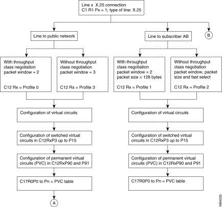 Configuration of an X.25 Line
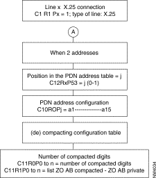 Configuration of an X.25 Line (Con't.)
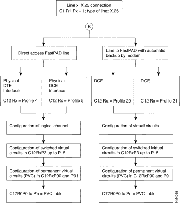 Configuration of an X.25 Line (Con't.)
The HDLC-T is governed by the software license (TRAN).
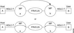
The FastPad allows any HDLC-compatible device using any protocol with error recovery, usually one delimited by flags, e.g. HDLC, SDLC, LAPB, PPP synch.,...to use HDLC-T features.
HDLC-T is a point-to-point connection. When the line is in service, the subscriber port uses the automatic calling behavior (C8R0, R4) to establish a logical link (C17R0) between two subscribers.
Class 17 Rec 0
For each entry, there are four fields (A, B, C, D):

C1 | R1 | C1 | R1 |
1 | 20 | 2 | 20 |
C12 | R1 | C12 | R2 |
0 1 2 | 82 28, 15 91, 1 (find entry in C17R0) | 0 1 2 | 82 28, 15 64tcb/s 91, 1 |
C17 | Rec 0 | C17 | Rec 0 |
0 | 1, 0, 0, 68 | 0 | 1, 1, 1, 71 |
C9 | Rec 4 | C9 | Rec 4 |
36 | 68 | 36 | 71 |
C9 | Rec 5 | C9 | Rec 5 |
36 | 1, 1, 0, 1 | 36 | 1, 1, 0, 2 |
C4 | Rec 7 | C4 | Rec 7 |
0 | 1, 1, 0, 0 | 0 | 1, 1, 0, 0 |
C8 | R0 | C8 | R0 |
0 | 80000071 | 0 | 80000068 |
C8 | R1 | C8 | R1 |
0 | 01, 80 | 0 | 01, 80 |
C8 | R4 | C8 | R4 |
0 | 1 | 0 | 1 |
C8 | R5 | C8 | R5 |
0 | CD* | 0 | CD* |
* refer to Chapter 4 "Encapsulation Type".
As soon as line 1 of 9000 00 is in service, port 1 will generate a call to reach 8000 00 71.
Project name: |
|
Customer @: |
|
Contact points: |
|
Date: |
|
Objective: |
|
Diagram: |
|
Node address: |
|
Port number: |
|
 Example
Class 1 R1: type of line | Class 1 R1: type of line | ||
<port #> : 20 | HDLC-T port # : | <port #> : 20 | HDLC-T port # : |
Class 12 R <port#>: | Connection parameters | Class 12 R <port#>: | Connection parameters |
0 | 82: HDLC profile | 0 | 82: HDLC profile |
P28 | speed | P28 | speed |
P32 P33 P91 | CRC check ( ) 0 = yes, ( ) 1 = no Nbr. of flag: 1 up to 15 Entry R in C17R0 | P32 P33 P91 | CRC check ( ) 0 = yes, ( ) 1 = no Nbr. of flag: 1 up to 15 Entry R in C17R0 |
Class 17 R0 |
| Class 17 R0 |
|
<R-1>
| A, B, C, D: 1,0, A: Entry Q in C8R0, R1, R4, R5 B: 0 1 calling, 1 called C: always 0 D : subscriber @, y: | <R-1>
| A, B, C, D: 1,0, A: Entry Q in C8R0, R1, R4, R5 B: 0 1 calling, 1 called C: always 0 D : subscriber @, z: |
C9 R4 | C9 R5 | C9 R4 | C9 R5 |
? y | ? 1,1,0,<port #> | ? Z | ? 1,1,0,<port #> |
C8 R0 | Remote @ | C8 R0 | Remote @ |
<Q-1> | CDZ | <Q-1> | ABy: |
C8 R1 | C9 R4 | C8 R1 |
|
<Q-1> | 01, 80 | <Q-1> | 01, 80 |
C8 R4 | Slow call time | C8 R4 | Slow call time |
<Q-1> | ( ) 0, No ( ) 1-99/*10s | <Q-1> | ( ) 0, No ( ) 1-99/*10s |
C8 R5 | Encapsulation type | C8 R5 | Encapsulation type |
<Q-1> | ( ) CD ( ) FD | <Q-1> | ( ) CD ( ) FD |
Frame relay (FR) is a frame mode transfer service for long distance communication (WAN: Wide Area Network). This service is based on the modified LAP-D structure (LAP-D: Link Access Procedure on D-channel). The term LAP-F stands for: LAP-for Frame mode support services. LAP-F data is multiplexed on (OSI) level 2.
Signalling relative to this service is managed by the LMI function (Local Management Interface = ITU-T Q.933 and ANSI T1.617 (See Chapters 10 and 13 of this manual).
LAP-F = ISO standard Q.922.
There are two types of frames:

Legend
DLCI | = | Data Link Connection Identifier |
DE | = | Discard Eligibility bit |
BECN | = | Backward Explicit Congestion Notification bit |
FECN | = | Forward Explicit Congestion Notification bit |
C/R | = | Command/Response indication bit |
msb | = | Most Significant Byte |
lsb | = | Least Significant Byte |
CRC | = | Cyclic Redundancy Check |
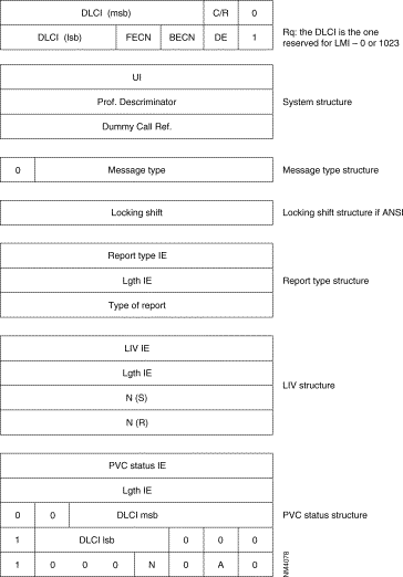
A local management interface of the frame service is offered. It enables a subscriber to determine the status of the PLLs (Permanent Logical Links) of the network and prohibits him from using a PLL which is not available. It supplies the procedures making it possible to detect and modify the following events:
For this purpose, the LMI of the subscriber (subscriber LMI) regularly transmits status enquiry messages. The LMI of the network (network LMI) replies with status report messages.
Two standard protocols are used for the local management interface:
FRTE: | FR Interface which acts like a terminal with regard to network; it supports the FRI, FRSNA, FRIP and FRT Frame-relay stack. |
FRCE: | FR interface which acts like a network with regard to a subscriber; it supports the FRA Frame-relay stack. |
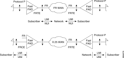 FastPad Configuration as Subscriber LMI (UNI) or Network LMI (NUI)
The FastPad can be configured as a subscriber LMI (UNI) (when it is facing a Frame Relay network), or a network LMI (NUI) (when it is facing an FR subscriber).
PLL = Permanent Logical Link
Sub-layer FR2.0 is the relay service. It manages only the bits representing the DLCI number in the heading.
Sub-layer FR2.1 is the frame switching and network congestion service. It manages the FECN, BECN, DE and C/R bits. RT2.0 and RT2.1 represent the core of Q.922.
Sub-layer FR2.2 represents the entire protocol as defined in Q.922. This protocol is generally active in the network periphery in the subscriber terminals.
The FastPad equipment offers several types of interfaces:
A) Subscriber Interface
B) Network Interfaces (FRTE)
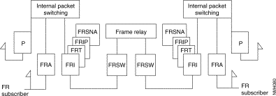
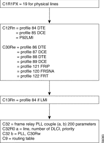
The following diagram gives the steps in the configuration process of a frame relay switch interface for an incoming and an outgoing line using the standard profile.
Additional parameters can be configured according to specific needs of the user.
Details of the parameters are described in Chapter 4.
The two lines to be configured must be on the same module.
 Configuration of Frame Relay Lines
The following diagram gives the steps in the configuration process of an HDLC or frame relay subscriber Interface using the standard profiles.
Additional parameters can be configured according to specific needs of the user.
Details of the parameters are described in Chapter 4.
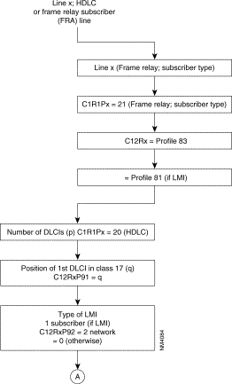

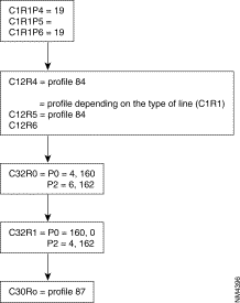
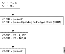
As these PLLs have no implicit physical output port, at least one frame relay line in class 1, recurrence 1 must be configured 18 (frame relay) enabling the routing tables to be configured in class 32.
The frame relay physical lines have an 84 profile (DTE) or 85 profile (DCE) defined in class 12. For these two profiles, only the parameters related to the physical line level are significant and possibly an 84 profile in class 13 which defines the LMI parameters (LMI is optional). LMI is not offered for transit couples (FRSW).
In class 30, the connection parameters of levels 2 and 3 of each PLL are defined by means of profiles (see available profiles).
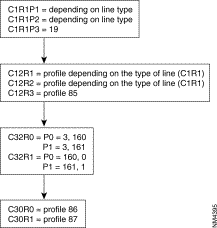
Class 32 represents the routing tables of all PLLs of the switch. There are two recurrences: one for incoming and one for outgoing lines. In each recurrence, the line number, the DLCI type and the DLCI number must be configured.
Recurrence 0 describes the physical lines with the different DLCI numbers and their types.
Recurrence 1 describes the physical lines of the PLL: the PLL number and the recurrence of the profile defined in class 30 of the PLL are indicated.
REMARK: For simplification, it is recommended that the virtual line number and the DLCI number of the PLL should be made equal on the physical line.
This rule is applicable, for adjacent nodes in which, as in this example, line 160 should have an odd profile number. This departs from the FastPad rule.


P4 = 21 
line 4 = FRA
P0 = 83 
FRA profile
P1 = 90,2 
2 DLCIs (101 and 88)
P2 = 91,10 
rest of description in C17R0 row 10
P3 = 92,2 
LMI of NUI (Network to user) type and still of network type
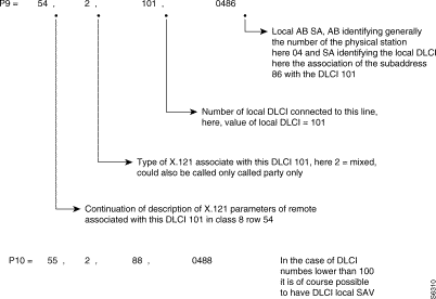 C17R0
C17R0
This local (AB SA) is used to format the address of the called number in the call packet as follows:

REMARK: It is possible to choose to configure only a local (AS) in C17 with all the restrictions that this implies. The calling address in the call-request packet then has the following form:


 FRSNA Example
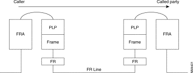

The SEP field of the multiframe protocol is negotiated between FRA. It is thus optional.


REMARKS
1. In these two examples, the X.25 VC encapsulated in FR is established end to end between two network elements via the FRA protocol.
2. In the following cases, the internal VC is established locally on each machine between the subscriber protocol (FRA, "P", SDLC, S.25, IP) and the protocol offered on the network interface (FRSNA, FRIP, FRT).


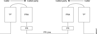


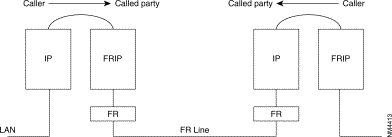

REMARKS
1. The FRI, FRSNA, FRIP and FRT stacks are represented by logic lines. As there may be several types of multiplexed stacks on a physical line, routing must be via the PLL ([65, 128] and [160, 239]) initialized in Class 32 Recurrence 1.
2. ZO (DNIC ZO AB) to PLL of normal/backup line output. The supporting VC (internal or external) is established by means of the routing tables (C9...). The end of the PLL allows the remote node to be identified by means of the associated ZO number. It is thus recommended that calls be routed by configuring the ZO of the remote equipment.

Example of routing table for PLL linking switch ZO = 00 with ZO = 01.
Routing table of switch 00:
Routing table of switch 01:
When several PLLs use different protocols, it is recommended that these internal VCs be routed by using different ZOs (one ZO per PLL) or routing at the level of the AB.
Two RFCs define the extension of MIB II to describe the Frame-Relay interface. RFC 1604 for DCE and RFC 1315 for DTE. Only global physical interface management is proposed and limited to the description in the MIB II of the interface group. Transmission groups is for subsequent study. One * means not used, ** means not available.
| Object Name | Meaning | Access |
|---|---|---|
ifIndex | Interface number | Read only |
ifDescr | Interface description | Read only |
ifType | Interface type | Read only |
ifMtu | Maximum octets in datagram | Read only |
ifSpeed | Bandwidth in bits per second | Read only |
ifPhysAddress | Lowest layer physical address | Read only |
ifAdminStatus | Interface status desired | Read-write |
ifOperStatus | Interface status current | Read only |
ifLastChange | Value of sysUpTime on interface | Read only |
ifInOctets | Total octets received on interface | Read only |
ifInUcastPkts | Number of packets to n + 1 layer | Read only |
ifInNUcastPkts | Non-unicast packets to n + 1 layer | Read only |
ifInDiscards | Inbound discarded packets/flow control | Read only |
ifInErrors | Inbound packets discarded due error | Read only |
ifInUnknownProtos | Inbound packets with protocol error | Read only |
ifOutOctets | Total octets transmitted on interface | Read only |
ifOutUcastPkts | Transmit requests from layer n + 1 | Read only |
ifOutNUcastPkts | Number non-unicast transmit requests | Read only |
ifOutDiscards | Outbound packets discarded/flow control | Read only |
ifOutErrors | Outbound packets discarded due error | Read only |
ifOutQlen * | Packet size of output queue | Read only |
ifSpecific | MIB-specific pointer | Read only |
IfName ** | not used |
|
IfInMulticastPkts ** | nbr of multicast frames received error free | Read only |
IfInBroadcastPkts ** | not used |
|
IfOutMulticastPkts ** | nbr of multicast frames transmitted error free | Read only |
IfOutBroadcastPkts ** | not used |
|
IfHCInBytes ** | nbr of bytes received useful for .DS3 interface | Read only |
IfHCOutBytes ** | nbr of bytes transmitted useful .DS3 interface | Read only |
IfLinkUpDownTrapEnble ** | trap transmission authorization | Read only |
IfHighSpeed | rate in Mbps, if lower that 1Mbps then set to 0 | Read only |
IfPromiscuousMode | set to False |
|
IfConnectorPresent | set to False |
|
Class 24 Rec X(6-8) 6 for M0, 7 for M1, 8 for M2 | Class 9 Rec 4 Subscriber number for VR | ||||||||
|---|---|---|---|---|---|---|---|---|---|
0 1 2 3 4
5 6 7 8 9 10 11 12 | 112 90,x 91,o 23,1 26,x
27,o 28,x 29,p 30,q 31,r 32,1 33,s 46,z | profile for virtual router number of LLC up to 200 (0-200) 1st entry in C17 Rec 0 up to 200 (0-200) intermediate routing routing option: 0 static route; 1 static route & default one.
static route type number of remote Ip @ range C31 Rec 14 1st entry in C31 Rec 14 entry in C31 Rec 15 for the default route (0-3) entry index in C31 Rec 7 for the Wan Ip @ always set to 1.(number of local range of Ip@) entry index in C31 Rec 8, 11 for the LAN Ip @ and its behavior. subscriber number.(default one is 95). | Class 9 Rec 5 SAP (virtual line) for VR | ||||||
x | 1,1,0,y |
| |||||||
|
|
| y= | 60 if on M0 | |||||
|
|
|
| 61 if on M1 | |||||
|
|
|
| 62 if on M2 | |||||
|
|
|
|
| |||||
|
|
|
|
| |||||
|
|
|
|
| |||||
|
|
|
|
| |||||
|
|
|
|
| |||||
|
|
|
|
| |||||
|
|
|
|
| |||||
|
|
|
|
| |||||
Class 31 Rec 7 Recurrence for the Wan Ip address (Host Id) |
| Class 31 Rec 19 for Community string | ||
r |
|
|
| 0 for read-only 1 for read/write 2 for trap messages |
Class 31 Rec 8 Recurrence for the LAN Ip address. |
| |||
s |
|
|
| |
Class 31 Rec 11 Recurrence for the behavior of the LAN Ip @ |
|
| ||
s | t,0,0,0,0,0 |
|
|
|
t: | entry index in C31 Rec 12,13 for the Local range of Ip @ |
| ||
Class 31 Rec 12 Recurrence where is define the LOWEST Ip @ of the range. |
| Class 31 Rec 20 for Client @(up to 6) X A, B, C, D, z A, B, C, D is the IP @ z: entry index(0-2) in C31 Rec 19 | ||
Class 31 Rec 13 Recurrence where is define the HIGHEST Ip @ of the range. |
|
| ||
Class 31 Rec 14 Mapping between the range of Ip @ and the LLC Id. |
| Class 31 Rec 21 for Trap DA (up to 3) | ||
p | A,B,0 |
|
|
|
| A:entry index in C31 Rec (12, 13) B: LLC Id(1-199) 0: field not used, always 0. |
|
| |
|
|
| ||
|
|
| ||
Class 31 Rec 15 up to three entries |
| Class 8 Rec 0 Remote X.121 @ | ||
q | B |
|
|
|
| B: for the LLC Id of the default route |
| Class 8 Rec 1 Fast select | |
Class 17 Rec 0 Mapping between the LLC Id and the remote X.121 @. |
| x 01, 80 optional | ||
o | A, B, C, 0 A: first entry in C8 B: LLC type; 0 calling, 1 called, 2 mixed, 3 datagramme C: LLC Id 0: field not used always 0. |
| Class 8 Rec 4 Slow call timer | |
|
| x 0 inactive | ||
|
| 1 steps of 10s | ||
|
| Class 8 Rec 5 Encapsulation type | ||
|
| x CC, 08, 00 for IP and RFC 1356 or Virtual Router. | ||
|
|
|
| CC, 03, CC for IP and FRA |
ISDN components include Terminals, Terminal Adapters, Network Termination devices, Line Termination equipment, and Exchange Termination equipment (see Figure 6-49).
Beyond the TE1 and TE2 devices, the connection point in the ISDN network are the Network Termination devices.
Beyond the NT1 and NT2, the next connection points are:
A number of reference points are specified in ISDN. These reference points define logical interface between functional groupings (See Figure 6-50)
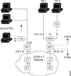
The ISDN exchange terminators are interconnected via communication devices using Common Channel Signaling System Nº 7 (CCSS#7). This is a connectionless mode.
Two main interface structures have been defined, the Basic interface and the Primary.
| Access | BRI | PRI |
|---|---|---|
| Channel | 2B + D | 30 B + D |
| Data rate | 2*64 + 16 = 144 kbps | 30*64 + 64 = 1984 kps |
| Real rate | 144 + 48 = 198 kbps | 1984 + 64 = 2048 kbps |
The difference between real rate and data rate is due to the fact that in addition to these channels ISDN provides for framing control and other overhead bits.
The interface connector used for the TEs and NTs is an 8 pin so-called RJ connector.
This connector is specified in the ISO 8877 standard. The RJ connector for ISDN is denoted as RJ-45 connector. The layout of this connector is shown in Figure 6-51. The maximum number of wires in the interface is 8, but mostly only 4 wires are used.
 Connector
| Pin | Signal |
|---|---|
1 | not used |
2 | not used |
3 | TD |
4 | TD |
5 | RD |
6 | RD |
7 | not used |
8 | not used |
Via the balanced transmit and received lines, power is distributed from NT towards the TEs.This power distribution takes place via a so-called phantom circuit.
This power source has a nominal voltage of 40 volts and should supply a power of at least 420 milliwatts.

Figure 6-52 illustrates the ISDN recommendations for the protocols in the different layers. Levels 2 and 3 are significant for D-channel.
For the physical layer, two protocols are possible:
These protocols describe how to transfer the information across the medium.The protocol of the physical layer is based on Time Division Multiplexing (TDM).
The bits are grouped together into frames of 48 bits each.
The nominal bit rate is 192 kbps. Every 250 µs one frame is transmitted. This results in a transmission of 4000 frames per second.
ISDN physical-layer frame format differs depending on whether the frame is outbound (from terminal to network) or is inbound (from network to terminal).
The Primary rate interface (E1) has a frame structure that consist of 32 time slots of 8 bits each.
The number of bits in a frame is 256. Every 125 µs one frame is transmitted. This results in a transmission rate of 8000 frames per second are transmitted, which results in a nominal bit rate of 2048 kbps.
Layer 2 of the ISDN signaling protocol is Link Access Procedure, D-channel, also known as LAP-D. LAP-D is similar to High-level Data Link Control (HDLC) and Access Procedure Balanced (LAP-B).
As LAP-D's extended acronym indicates, it is used across the D-channel to ensure that control and signaling information flows and is received properly. LAP-D's frame format (see Figure 6-53) is very similar to that of HDLC and like HDLC, LAP-D uses Supervisory, Information and Unnumbered frames. The contention mechanism used on D-channel is the Carrier Sense Multiple Access - Collision Resolution (CSMA/CR).
The LAP-D protocol is formally specified in ITU-T I.441 (= Q921).
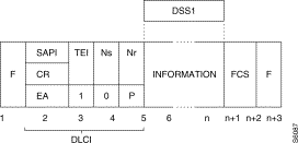
DLCI: Data Link Control Identifier
SAPI: Service Access Point Identifier
E/A: Address Field Expansion Bit D
C/R: Command/Response Bit
TEI: Terminal End Point Identifier
DSS1 : Digital Signaling System one (D protocol).
 Address Field
The LAP-D address field is two bytes long. The address field identifies the intended receiver of the command frame or the transmitter. The LSB of the first byte is '0' indicating an extension address of the address field. The LSB of the second byte is a '1' indicating the end of the address field.
C/R bit indicates whether a frame is a command or a response. The user side will send commands with the C/R bit set to '0' and responses with the C/R bit set to '1'. The network side will do the opposite.
The SAPI field identifies the Service Access Point (SAP) where the Data Link Layer services are provided to the layer 3 entities. The SAPI field enables 64 different SAPs to be addressed. Table 6-17 gives an overview of the possible SAPI values.
| SAPI | RELATED ENTITY |
|---|---|
0 | Call control procedure |
1 | Packet communication protocol Q.931 |
16 | Packet communication protocol X.25 |
63 | Data Link Layer management procedures |
XX | Reserved for further standardization |
The TEI field identifies the network entity for which the frame is intended or from which the frame is coming. The TEI field allows the addressing of 128 different TEIs.Table 6-18 gives an overview of the possible TEI values.
| TEI | RELATED ENTITY |
|---|---|
0—>63 | Non automatic TEI assignment user equipment |
64—>126 | Automatic TEI assignment user equipment |
127 | Broadcast TEI |
The Control field is two bytes for Information frames and Supervisory frames and one byte for Unnumbered frames. Noted that only the Set Asynchronous Balanced Mode Extended is used.
The FCS is based on a Cyclic Redundancy Check method. It is generated over the Address field, the Control field and the Information field.
The network layer has been described in the I.451 (Q=931) recommendation. The protocol used is D protocol. Figure 6-55 shows the general message structure.
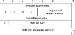
The first three parts are common to all messages and must always be present. The last part is specific for each message type.
The purpose of the protocol discriminator is to distinguish messages for user-network call control from other messages within this protocol and others standards. Table 6-19 gives an overview of the possible value.
| VALUE | USE |
|---|---|
09—>0F | Other messages within L451 |
10—>3F 50—>FE | X.25 in D-channel |
| 0 0 0 0 | Length of Call Reference Value | |
|---|---|---|
Flag | Call Reference Value
| |
The purpose of the call reference flag is to identify the call or facility registration. The call reference flag can have the values '0' and '1'. The originating side sets the call reference flag to '0'.The destination side always sets the call reference flag to '1'.
The purpose of the message type is to specify the function of the message being sent. The message type is the third part of every message. The message type field consists of one byte. Bit 8 is reserved for extension.
ex: 05 set-up
07 connect
The information elements carry the actual signaling information between the subscriber and the network. For the information elements, two categories are possible.
Single Byte
1 | Information | Contents of Information |
The MSB is set to 1.This indicates a single byte information element.
Variable length
0 | Information Identifier |
Length (Byte)
| |
Contents
| |
The MSB is set to 0. This indicates a variable length information element.
The information elements are relative to:
Figure 6-56 shows the numbering plan. I.330 defines the dialing and addressing rules, I.331 defines the numbering plan (E.164).
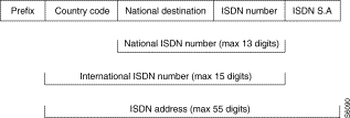 Numbering Plan
Prefix
The prefix must be used when making an international connection.
Country Code
The country code is used to select the country of destination.
National Destination
The national destination is used to select a geographical location within the selected country.
Subscriber number
The subscriber number is used to identify the user within the selected geographical place.
ISDN Subaddress
The ISDN sub-address is used to identify the user within a certain subscriber number.
Configuration of ISDN is governed by optional software licenses. Corresponding codes are CD (D-channel), CBAS (B-channel with signaling) and PAQD (packet mode on D).
In X.25, the ISDN function (profile 47) connects, in X25, the terminals of the FastPad switches with subscribers via the ISDN and provides a back-up solution when the main line (LL) is out of order or when there is no more LC available. ISDN stack mixed with others functions provides services as Multiple back-up, Dynamic allocation of bandwidth according to overflow thresholds.
By Leased Line, the reader should imagine a direct line between FastPads or over an IPX Frame-Relay network (one LL is composed of network PVC segments). In the second case, the Frame-Relay stack used in front of the IPX is an FRI one since, on the B-channels, only the X.25 protocol is allowed by the FastPad.
Figure 6-57 and Figure 6-58 illustrate different connection types.
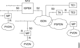 Different Connection Types
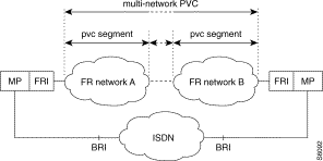 Different Connection Type
The ISDN equipment meets the ITU-T requirements concerning ISDN:
Calling Line Identification Presentation (CLIP)-Q.951.3
With this supplementary service, the called party can "see" the ISDN number of the calling party during an incoming call.
Direct Dial In (DDI)-Q.951.1
This supplementary service enables a user to make a direct call to another user on a ISPBX or other private system, without operator intervention.
Sub Address (SA)-Q.951.8
Used to address a specific terminal equipment connected to a bus in multipoint configuration.
There are two kinds of ISDN kits in the FastPadmp range. One for FRX series and another one for the rest of the range.
For the FRX the S0 plug is a part of the equipment and the kit is composed of two elements which are:
For the rest of the range the ISDN kit has three components:
The interface board is plugged on the port in use for the D-channel. The following port numbers (12 modulo) are assigned for the D-channel connection: 0, 3, 6, 9. If n is the number of the D-channel port, then n+1 and n+2 are reserved for the B-channels. If only one B-channel is used then the n+2 port is available for other protocols. In all cases (except for mp6, FRX 3W and 4W), with the external adapter box, the n+1 port is not available even if no B-channel is used (X.25 packet switching on D-channel), because of the physical connection with the back-panel. The following table shows a summary.
Equipment Type | Port Number | S0 / module | S0 / unit |
mp6 | 0 | 1 | - |
mp | 0, 3, 6, 9 | 4 | - |
mp12 | 0, 3, 6, 9(12 modulo) | 4 | 12 |
mpr | 0, 3(12 modulo) | 2 or 4(m2) | 8 |
The S0 interface is in service when power is detected on the phantom circuit is detected. Service parameter 35 (0-255)*200ms is the scanning time, and 36 (0-255) the number of attempts.
Activation is done by parameter 37 (0-255)*200ms. The stand-by mode is done by parameters 38(0-255)*200ms if NT and 39 if TE.
Parameter 56 specifies how many B-channels are used on the BRI:zero when only packet mode is used on D-channel, otherwise one or two. The default value is two.
Subscribers, as defined previously, can establish connection with private subscribers behind FastPad devices using X.25 packet-switching on B-channels. This mode of information transfer can also be used to interwork with the PSPDN to connect or to be connected with an X.121 subscriber, by using a specific gateway which assumes the necessary translation between the two networks.
A device is fully identified according to service parameters. Some of them can be managed by users others depending on the protocol and are assigned and managed by the network.
Par 44 T E I Assignment | Behavior |
0 | at start up |
1 | on set-up |
Protocol Identification at layer 1 must be X.31.This means that for a connection with a TE2 using a TA, this one has always to be in transparent mode at 64Kb/s because no other rate adaptation than X.31 is supported, such as ECMA 102, V110/X30 etc.
Protocol Identification at layer 2 can be either X.25 SLP (single link procedure) or X.25 MLP (multi-link procedure) if the S0 interface, belongs to or is defined within a bundle.
Protocol Identification at layer 3 must be X.25.
Values for LLC are fixed and can not be changed. However, the user is able to act on the behavior of the device according to parameter 74, which defines if LLC is transmitted and/or checked. Its different values are shown in Table 6-23.
Par 74 Different Values | Behavior | |
transmit | checked | |
00 | no | no |
01 | yes | no |
02 | no | yes |
03 | yes | yes |
The user can act on the HLC (parameter 71), as for LLC and more, by choosing which features of tele-services (parameter 73) will be present in the IE's (information elements) according to both standard coding types (parameter 72). The following tele-services are or can be taken into account by the equipment and are illustrated in Table 6-24.
Par 73 | Par 72 | ||
value | feature | value | coding |
193 | ISO | 145 | ITU-T |
128 | unknown | 209 | national |
255 | not defined | 209 | national |
Table 6-25 shows different actions that can be done, concerning the HLC, which are the same as for LLC.
Par 71 different values | Behavior | |
transmit | checked | |
00 | no | no |
01 | yes | no |
02 | no | yes |
03 | yes | yes |
Parameter 64's value is an index used to define which address in class 10 is assigned to the S0 interface (see Figure 6-59). Up to 36 addresses can be defined.
 Parameter 64 Defines Which address is Assigned to SO Interface
When more that one device is connected on the same bus it is useful and better to be able to identify each device. For that there are two possibilities:
1. SA, can be used by everybody and can have up to 4 digits. The specific character(:) is used as prefix for the SA. A FastPad device can be identified as follows:
2. by the E.164 address of the basic rate access
3. by the E.164 and a sub-address
4. by the sub-address
These three cases are shown in Figure 6-60.
On BRI 41079340, mp A has one S0 connection via port 0 and its SA is 10. mp B has also one connection, but without SA, via its port 0.
On BRI 46299390, mp B has another S0 connection via port 3. It is identified by its own SA which is 1890.

The corresponding configuration is the following (See Table 6-26).
M c x A | M c x B |
Class 12 rec 0 | |
0 47 default profile 1 64,0 raw 0 in C10 2 62,1 SA used | 0 47 1 64,0 2 62,0 SA not used (default value) |
Class 12 rec 3 | |
| 0 47 1 64,1 raw 1 in C10 2 62,1 |
Class 10 rec 0 | |
0 41079340:10 | 0 41079340 1 :1890 |
The next sheet shows a Set-up capture.
SAPI TEI FType Q921 Ty Q931 Msg *
0 64 INFO SETUP
08000000008910892086048333333337
010081154280813E410CA00462993900
Chan SAPI c TEI FType Ns Nr P *
r F *
TE 0 0 64 INFO 0 0 0
PrD CRL Ref CF Q931 Msg FrTime F*
8 1 0 0 SETUP 9506 G
1
0089 Len CS
4280
Bearer Capability 2 0
Coding Std.................ITU-T
Info Trans Cap.....Unres Digital
Transfer Mode............Circuit
Transfer Rate..........64 Kbit/s
108 Len CS
813
Channel Identification 1 0
Interface Id Present..Implicitly
Interface Type.............Basic
Channel................Preferred
D-channel.....................No
Channel Selected.............Any
9 Len CS
E
Shift 0
Shift Type...........Non-Locking
Codeset........................6
208 Len CS
410
Undefined Element 1 6
604833333333 Len CS
CA0046299390
Calling Party Number 10 0 Set-up sent by the FastPad with default
Number Type...........Subscriber HLC & LLC
Number Plan..............Unknown
Presentation.............Allowed
Screening...User Prov Unscreened
Number Digits
46299390
70833333333 Len CS
09041079340
Called Party Number 9 0
Number Type..............Unknown
Number Plan..............Unknown
Number digits
41079340
7089ACE Len CS
C580966
Low Layer Compat. 5 0
Coding Std.................ITU-T
Info Trans Cap.....Unres Digital
Transfer Mode............Circuit
Transfer Rate..........64 Kbit/s
Layer Id.................Layer 1
Proto Id....................X.31
Layer Id.................Layer 2
Lay 2 Proto......X.25 Link Layer
Layer 2 information
E
6
709C Len CS
D211
High Layer Compat. 2 0
Coding Std.................ITU-T
Interpret....First High Lay Used
Pres Method...Hi Lay Prot Profil
Hi Lay Char.............OSI Appl
A Len CS
1. Sending Complete 0
2. DDI, can be used only if the user subscribes to this supplementary service (Telecom company, ISPBX). The last digits, one or more according to the subscription, of the ISDN number can be different.
Suppose now, the ISDN number of a basic rate access is 46299390 and the DDI behavior is subscribed for five; the following E.164 address will identify a single BRI (See Figure 6-61).
 E.164 Address Identifies a Single BRI
The configuration for this example is:
M P |
Class 12 rec 0 |
0 47 |
1 64,0 |
2 63,1 DDI behavior |
Class 10 rec 0 |
0 46299391 |
In fact DDI is useful behind an "intelligent" NT2, such as ISPBX. For example see Figure 6-62.

DDI's numbers are assigned to the Primary rate interface from the point of view of the network. The ISPBX is able to send the incoming Set-up on the correct BRI. Each device connected in a multipoint configuration can use the sub-addressing system to be identified.
Mapping table
To establish a connection over ISDN network between two entities, it is necessary to map two different numbering plans. An X.121 address (max 15 digits) in (C22 rec0) with an E.164 address (max 28 digits) in (C22 rec 1), as shown in Figure 6-63.

The corresponding mapping table in the configuration will be:
mp A | mp B |
Class 22 rec 0
| |
0 800010 | 0 900000 |
Class 22 rec 1
| |
0 46299390 | 0 41079340 |
Behavior
Each remote ISDN point is linked to a behavior (C22 rec2) and an X.25 profile (C30 rec (0-15)). It is also possible to define up to five optional actions. The structure of Class 22 rec2 is the following:
Class 22 rec 2
0 Byte 0, Byte 1, Byte 2, and up to five optional actions.
Byte 0.
Defines the way the connection can be established. The three different values that can be used are:
Byte 1.
This byte is in fact an index, used to define which recurrence will be used in Class 30. In this way a X.25 profile is assigned dynamically on a B-channel according to the remote ISDN number. An X.25 profile can be used by different ISDN numbers as soon as the X.25 service parameters are compatible. Up to 16 different connection profiles can be defined in class 30.
Byte 2.
This byte is not used and is always set to 00.
The example in Figure 6-63 could be now as followed in Figure 6-64. The configuration could be as shown in Table 6-28.

From 9000 00 it is only possible to reach 8000 10.
From 8000 10 it is impossible to reach 9000 00.
Between 1005 68 and 80010 the establishment phase can be initiated by both.
mp A | mp B | mp C |
Class 1 rec 2 | ||
0 900000 | 0 800010 | 0 100568 |
Class 10 rec 0 | ||
0 41079340 | 0 46299390 | 0 54891204 |
Class 22 rec 0 - X.121 @ - | ||
0 800010 1 100568 | 0 0 800010 |
|
Class 22 rec 1 - E.164 @ -
| ||
0 46299390 1 54891204 | 0 41079340 0 46299390 |
|
Class 22 rec 2 | ||
0 60,00,00 60 for outgoing 00 for rec 0 in C30 00 because not used | 0 50,00,00 50 for incoming 00 for rec 0 in C30
1 70,00,00 | 0 70,01,00 70 for both-way 01 for rec 1 n C30 |
Class 30 rec 0 | ||
0 4 DTE logical profile | 0 5 |
|
DCE logical profile |
|
|
Class 30 rec 1 | ||
|
| 0 4 |
As explained previously, for node 8000 10 two different ISDN remote points use the same X.25 profile, here profile 5.
When there is no more switched virtual circuit on a B-channel, this one is disconnected after a time-out defined by parameter 60(1-250)*1s. The default value is zero and means no time out.
For an outgoing call, the most important address is the X.121 address (Class 22 rec0).
For an incoming Set-up, the most important address is the E.164 address (Class 22 rec1).
Up to 250 different mappings can be defined in class 22.
Optional actions.
An action is a one byte coded by quartet. The MSB quartet defines the action type, the LSB quartet defines the value assigned to the action. There are six different actions for ISDN, some of its refer to specific paragraph. When an action is not mentioned, the behavior is the default one.
C22 rec 1 | C22 rec 2 | ||
0 *1 | xxxyyyzz ; | 0 1 | 50,00,00,01 50,00,00 |
Specific characters
Certain characters can be used instead of some digits within an address or to replace a complete one. Table 6-29 lists characters and their meanings.
Characters | meaning |
> * | indicates an offset and is used for extraction |
= | used to mask any digits within an address |
; | used to replace any address |
: | used as a separator, prefix to indicate a SA |
* For more information on extraction refer to next sheet.
As seen in the behavior; one can choose the manner of a Set-up: incoming, outgoing, or both-way. The use of these characters depends on this behavior, as shown in the following example.
 Example
Class 22 rec 0 | Class 22 rec 1 | Class 22 rec 2 |
0 12345678 | 0 41079340 | 0 60,00,00 |
1 378 | 1 99891604:0001 | 1 70,00,00 |
2 456= = = | 2 46299390 | 2 70,00,00 |
3 ; | 3 36122018 | 3 70,00,00 |
4 | 4 12 = = | 4 50,00,00 |
5 | 5 ; | 5 50,00,00 |
0 = Mapping between a X.121 @ and an E.164 @, for an outgoing Set-up.
1 = Any X.121 @ beginning with the digits 378 will generate a Set-up with the corresponding E.164 @. Incoming Set-ups, for the specified E.164 address, are accepted. The length of the X.121 address does not matter.
2 = Same behavior as in case(b) but here the length is checked.
3 = Any X.121 @ will generate the Set-up. Incoming Set-ups, for the specified E.164 address, are accepted.
4 = Any E.164 @ beginning with 12 followed by two more digits will be accepted.
5 = Any E.164 @ will be accepted.
Extraction case. The E.164 address is built from a part of or the complete X.121 address.This can be useful when the user is building his or her own network from scratch. Otherwise, for a network already having a numbering plan, it is more tricky to use.
The extraction uses two tools:
1 = >, which is a specific character and indicates an offset position within an X.121 address.
2 = A4 or Action 4x, is used to specify, from the offset, the number of digits (value of x(0-f)) to extract, to form the E.164 address.
Table 6-31 illustrates some examples.
Class 22 rec 0 | Class 22 rec 1 | Class 22 rec 2 |
0 9025> | 0 4512 | 0 70,00,00,44 |
1 41079340 | 1 | 1 60,00,00,48 |
2 12345> | 2 462993 | 2 70,00,00,42 |
3 ; | 3 | 3 60,00,00,48 |
0 = Extraction of four digits after the offset. If the called X.121 address is 902512345, the called E.164 address will be 45121234.
1 = Extraction of eight digits from the beginning because no offset is specified. The E.164 address will be 41079340.
2 = Extraction of two digits after the offset. For this X.121 address,1234578, the E.164 address will be 46299378.
3 = Extraction of eight digits from the beginning of any X.121 address. If the called X.121 address is 1789101012, the E.164 address will be 17891010.
Table 6-32 shows in which cases it can be used. DC means Do not Care.
Specific character | Incoming
| Outgoing | ||
C22 rec0 | C22 rec1 | C22 rec0 | C22 rec1 | |
> | DC | / | yes | / |
= | DC | yes | yes | DC |
; | DC | yes | yes | DC |
: | / | yes | / | yes |
Multiple backup
Sometimes the remote ISDN point can be busy, or out of order. That is why it is useful to have more than one E.164 address for each X.121 address. This principle is called multiple backup. For one X.121 address there is a list of a maximum of 10 E.164 addresses.
To use multiple backup, it is necessary:
1 = To add action types, in the behavior(C22 rec 2).
2 = To use parameters 65,66,67,68 of the ISDN profile (profile 47).
When, for a X.121 address, the call request must be sent towards the ISDN network, the system looks for the corresponding E.164 address and checks if action five is present. If yes, it means there is a list for this X.121 address and the mapping table is scanned from top to bottom.
Each E.164 address is stored in a temporary table according to its priority and its position during the scrolling of the mapping table.
With the priority, the order within a list can be changed at any time.
Figure 6-66 illustrates this principle.
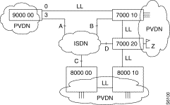
From 9000 00, the user can reach a subscriber "Z" via node 7000 10 and then 7000 20 using the leased line 0. If a problem appears on line 0, there are backup solutions over ISDN with two E.164 addresses to reach the subscriber "Z" which belongs to the area 7000.
From 9000 00, it is also possible to reach area 6000 and 5001 via ISDN number X and Y.
The mapping table in node 9000 00 would be, as follows.
Class 12 rec 3 | Class 22 rec 0 | Class 22 rec 1 | Class 22 rec 2 |
0 47 1 65,5 2 66,10 3 67,3 4 68,100 | 0 7000 1 7000 2 6000 3 5001 | 0 B 1 D 2 X 3 Y | 0 70,00,00,5 1 70,00,00,61 2 70,00,00 3 70,00,00 |
The list for backup over ISDN is:
1) address B, with 2 attempts.
2) address D, with 1 attempt. A Set-up will be sent only if the two B-channels of the BRI "B" are busy or if the node 7000 10 is out of order. A backup of nodes or parts of network is possible, as for a leased line.
After sometimes another ISDN number is included in the list and the first choice is changed, it will be number D. Always for node 9000 00 the configuration would be now the following.
Class 12 rec 3 | Class 22 rec 0 | Class 22 rec 1 | Class 22 rec 2 |
0 47 | 0 7000 | 0 B | 0 |
1 65,5 | 1 7000 | 1 D | 70,00,00,52,70 |
2 66,10 | 2 6000 | 2 X | 1 |
3 67,3 | 3 5001 | 3 Y | 70,00,00,52,71 |
4 68,100 | 4 7000 | 4 C | 2 70,00,00 |
|
|
| 3 70,00,00 |
|
|
| 4 70,00,00,61 |
The list to back up the connection with 7000 will be:
1) D, with two attempts. D is first because it has the highest priority.
2) B, with two attempts.
3) C, with one attempt.
The general parameters are the default ones and are not changed. There will be 5s between each attempt, 3 cycles with 10 s between each.
On an incoming call the following processes are executed, when Bearer, Low layer Compatibility and High Layer Compatibility are accepted.
The process is shown in Figure 6-67.
If DDI is specified in the subscription and the FastPad doesn't use it, we accept all the ISDN numbers and check only the sub-address.
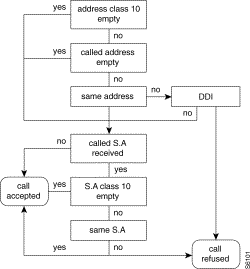
Hypothesis: one B-channel is already used.
The decision to multiplex a call is made on an outgoing call, according to the E.164 address.
The called address is compared with the remote user address of the B-channels already connected.
If the comparison is right, the sub-addresses are compared, otherwise another B-channel is opened.
If there is no sub-address within the called address, we think we want to reach a device connected to the first remote ISDN point and we do not care about a previous Sub-address in the first call.
If both sub-addresses are present and identical, or both absent, we multiplex the call on the same B-channel.
In all others cases another B-channel is opened.
The port which defines the D-channel is used by the routing function to send the Set-up. It is also possible to define the first choice as being one port used by a B-channel. However, in this case you must note the destination of the first call, so as to be able to activate back-up.
There is a way to use X.25 packet switching on B-channels to interconnect FastPad's subscribers or PVDN over ISDN and PSPDN networks.The condition is the existence of a gateway between both networks.
A common E.164 address can be used by everybody to make a call from ISDN towards PSPDN. Specific addresses, for specific customers, can be assigned on request by the Telecom company if need be. Anyhow the called site must subscribe to the reverse charging facility.
For a call from PSPDN towards ISDN, the called address, in deed the E.164 address of the remote ISDN point, is preceded by a prefix which indicates this call must be routed towards the gateway. Just a sub-address will be present in the called address field of the X.25 call request generated by the gateway on the B-channel.
Figure 6-68 illustrates this kind of connection.

If subscriber A wants to reach B, there will be two steps in the network:
1) Set-up over ISDN with the address is 36086464. A point-to-point connection is established with the gateway.
2) A call request is sent with the address 1921309102.
If subscriber B wants to reach A, there will be three steps in the network.
1) B sends a call request with the address 43 41079340 05.
2) The gateway sends a Set-up over ISDN with the address 41079340.
3) The gateway sends a call request on a B-channel with the address 05.
For the node 196810 the configuration would be:
Class 22 rec 0 | Class 22 rec 1 | Class 22 rec 2 |
0 19213= = | 0 36086464 | 0 70,00,00 |
Type of line, are the following: 14 for D-channel, 15 for B-channels
Type of profile, are the following: 47 for D-channel in C12
Anyone for B-channel in C12 because those are dynamically assigned in function of the remote E.164 address and are defined in C30. However as soon as more than one logical group channel is used those ones will must be defined also in C12 because the buffers are reserved at the initialization of the equipment according to C12.
Type of access, the access is always a BRI with TE behavior.
Type of ISDN. ISDN has not been implemented at the same time and does not follow all the specifications of ITU-T. Within a country the ISDN network is changing step-by-step and sometimes BRI doesn't have the same level of implementation (Digital Version). That is why in the ISDN profile there are two parameters to specify in which country and with which Digital Version the equipment must be configured.
In Europe, countries try to have a network meeting the requirements of ETSI. In some countries it is necessary to pass tests to be allowed to be connected on its ISDN networks, when ETSI's requirements are not met. There are specific values to set in the ISDN profile where FastPad equipment has been approved.
0 for France
1 for United Kingdom
2 for Switzerland or Netherlands
3 for ETSI
0 DN2 in France
1 DN3 in France
Switzerland | Netherlands | |
2,2 44,0 48,4 49,30 51,10 | 2,2 44,0 48,4 49,30 51,60 |
TEI assignment on In & Out set-up T303 T305 T310 |
Normally we do not must change the parameter's value of LAP-D and D protocol.
Point-to-point connection
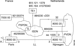
The connection between Paris, France and Nijmegen, the Netherlands, using a leased line, is backed up using the ISDN network.The Basic Rate Interface in France follows the ETSI requirements and the national ones in Netherlands. The access node in Nijmegen will used the sub-address 1005. Each access can use two B-channels if need be and the connection can be established by both sites. The length of the X.121 address will be checked.
 Point-to-Point Connection
The complete address for the node located in Nijmegen is: 19 0931 80 884026:1005.
Prefix 19, for outgoing call from France to a foreign country.
Prefix 0931, to identify the Netherlands.
Prefix 80, to indicate the town of Nijmegen.
Address of the BRI is 804026.
Sub-address 1005 identifies the device connected on the bus.
The complete address for the node located in Paris is: 09 33 1 46299390.
Prefix 09, for an outgoing call from Netherlands to a foreign country.
Prefix 33, to identify France.
Prefix 1, to indicate the Parisian area.
Address of the basic BRI is 46299390.
Table 6-34 shows this configuration.
Node: 9000 00 | Node: 8000 10 |
Class 1 rec 1 | |
0 14 Type of line for D-channel 1 15 Type of line for B-channels 2 15 3 1 | 0 14 1 15 2 15 3 1 |
Class 12 rec 0
| |
0 47 ISDN profile 1 2,3 Country; Euro-ISDN(ETSI) 2 64,0 Raw in C10 for the E.164 @
default values 56,2 Number of B-channels | 0 47 ISDN profile 1 2,2 Country; 2 for Netherlands 2 44,0 TEI allocation at START up 3 48,4 t 303 4 49,30 t 305 5 51,60 t 310 6 62,1 Sub-address is used 7 64,0 Raw in C10
default values 56,2 |
Class 12 rec 3
| |
0 4 | 0 5 |
Class 10 rec 0 | |
0 46299390 | 0 884026:1005 |
Class 22 rec 0 | |
0 8000 = = = = | 0 900000 = = |
Class 22 rec 1 | |
0 19093180884026:1005 | 0 0933146299390 |
Class 22 rec 2 | |
0 70,00,00 70: Set-up in the both way. 00: Rec 0 in C30 00: Not used | 0 70,00,00 |
Class 30 rec 0 | |
0 5 1 22,1 2 23,2 | 0 4 1 22,1 2 23,2 |
Class 9 rec 0 | |
0 8000 | 0 9000 |
Class 9 rec 1 | |
0 2,2,0,3,0 | 0 2,2,0,3,0 |
Multipoint connection
TE1 can reach both nodes. For Paris, the connection can be established from both sites. For Nijmegen only from TE1. TE1 is located outside the Parisian area. The B-channel is cleared after a time out of 10s. See Figure 6-70.
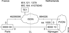
The X.25 TE1 works in two addresses mode. The X.25 profile number 2 is used. The configuration is the following (See Table 6-35).
Node: 9000 00 | Node: 8000 10 |
Class 1 rec 1 | |
0 14 Type of line for D-channel 1 15 Type of line for B-channels 2 15 3 1 | 0 14 1 15 2 15 3 1 |
Class 12 rec 0 | |
0 47 ISDN profile 1 2,3 Country; Euro-ISDN(ETSI) 2 64,0 Raw in C10 for the E.164 @ 3 60,10 Time out for 0cv on B.
default values 56,2 number of B-channels | 0 47 ISDN profile 1 2,2 Country; 2 for Netherlands 2 44,0 TEI allocation at START up 3 48,4 t 303 4 49,30 t 305 5 51,60 t 310 6 62,1 Sub-address is used 7 64,0 Raw in C10 8 60,10 default values 56,2 |
Class 12 rec 3
| |
0 4 | 0 5 |
Class 10 rec 0 | |
0 46299390 | 0 884026:1005 |
Class 22 rec 0 | |
0 8000 = = = = 1 1379 | 0 900000 = = 1 |
Class 22 rec 1 | |
0 19093180884026:1005 1 41079340 | 0 0933146299390 1 093341079340 |
Class 22 rec 2 | |
0 70,00,00 70: Set-up in the both way. 00: Rec 0 in C30 00: Not used 1 70,01,00 01: Rec 1 in C30 | 0 70,00,00 1 50,01,00 50: Incoming Set-up 01: Rec1 in C30
|
Class 30 rec 0 | |
0 5 1 22,1 2 23,2 | 0 4 1 22,1 2 23,2 |
Class 30 rec1 |
|
0 2 1 2,0 2 22,1 3 23,2 2 45,2 | 0 2 1 2,0 2 22,1 3 23,2 4 45,2 |
Class 9 rec 0 | |
0 8000 1 1379 | 0 9000 |
1 1379 |
|
Class 9 rec 1 | |
0 2,2,0,3,0 1 1,1,0,0 | 0 2,2,0,3,0 1 1,1,0,0 |
Multiple Back-Up
There is already a back-up solution over ISDN when the leased line is out of order. But if the remote access of node 800010 or the node itself is also out of order, another back up solution is possible with node 800020 (see Figure 6-71).
The number of attempts for the first E.164 address of the list will be equal to 2 and 1 for the last one.
The values for the time-out and number of cycles are the default ones.
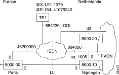
The configuration is now as follows.
Node: 9000 00 | Node: 8000 10 |
Class 12 rec 0 | |
0 47 ISDN profile 1 2,3 Country; Euro-ISDN(ETSI) 2 64,0 Raw in C10 for the E.164 @ 3 60,10 Time out for 0cv on B.
default values 56,2 number of B-channels 65,5 time out between attempts 66,10 time out between cycle 67,3 number of cycle 68,100 max time out for the multiple back up | 0 47 ISDN profile 1 2,2 Country; 2 for Netherlands 2 44,0 TEI allocation at START up 3 48,4 t 303 4 49,30 t 305 5 51,60 t 310 6 62,1 Sub-address is used 7 64,0 Raw in C10 8 60,10 default values 56,2
|
Class 22 rec 0 | |
0 8000 = = = = 1 1379 2 8000 = = = = | 0 900000 = = 1 |
Class 22 rec 1 | |
0 19093180884026:1005 1 41079340 2 19093180884232 | 0 0933146299390 1 093341079340 |
Class 22 rec 2 | |
0 70,00,00,52 70: Set-up in the both way. 00: Rec 0 in C30 00: Not used 52: 2 attempts for the E.164 @ in raw 0 rec1 1 70,01,00, 01: Rec 1 in C30 2 70,00,00,61 61: 1 attempt for the last E.164 @ of the list | 0 70,00,00 1 50,01,00 50: Incoming Set-up 01: Rec1 in C30
|
Class 30 rec 0 | |
0 5 X25 DCE trunk 1 22,1 2 23,2 | 0 4 X25 DTE trunk 1 22,1 2 23,2 |
Class 30 rec1 | |
0 2 X25 private 1 2,0 2 22,1 3 23,2 2 45,2 2 @ mode | 0 2 1 2,0 2 22,1 3 23,2 4 45,2 |
Class 9 rec 0
| |
0 8000 1 1379 | 0 9000 1 1379 |
Class 9 rec 1
| |
0 2,2,0,3,0 1 1,1,0,0 | 0 2,2,0,3,0 1 1,1,0,0 |
For node 800020 it will be:
class 12 rec 0 |
0 47 1 2,3 2 64,0 raw 0 in C10 3 63,1 DDI behavior |
class 10 rec 0 |
0 884230 |
Internetworking with PSPDN
The E.164 address of the gateway(G) is 36086464. According to the way of the call the gateway uses two different profiles as follows:
From ISDN to PSPDN a DCE logic.
From PSPDN to ISDN a DTE logic.
The interworking is allowed only with node 900000. Node 7000 is located in PARIS.
See Figure 6-72 for an example.
 Example
When subscriber A would like to reach the internal function of node 7000, he will must call with the address 19213037499Dxxyy.
From node 7000 subscriber B will must call with the address 4314629939099Dxxyy.
In the configuration the following has been added (bold).
Class 22 rec 0
| |
0 8000 = = = = 1 1379 2 8000 = = = = 3 192 4 | 0 900000 = = 1 |
Class 22 rec 1 | |
0 19093180884026:1005 1 41079340 2 19093180884232 3 36086464 4 36086464 | 0 0933146299390 1 093341079340 |
Class 22 rec 2 | |
0 70,00,00,52 70: Set-up in the both way. 00: Rec 0 in C30 00: Not used 52: 2 attempts for the E.164 @ in raw 0 rec1 1 70,01,00, 01: Rec 1 in C30 2 70,00,00,61 61: 1 attempt for the last E.164 @ of the list 3 60,02,00 02: Rec 2 in C30 ISDN to PSPDN 4 50,03,00 03: Rec 3 in C30 PSPDN to ISDN | 0 70,00,00 1 50,01,00 50: Incoming Set-up 01: Rec1 in C30
|
Class 30 rec 0 | |
0 5 X25 DCE trunk 1 22,1 2 23,2 1 22,1 2 23,2 | 0 4 X25 DTE trunk |
Class 30 rec1 | |
0 2 X25 private 1 2,0 2 22,1 3 23,2 2 45,2 2 @ mode | 0 2 1 2,0 2 22,1 3 23,2 4 45,2 |
Class 30 rec2 | |
0 0 PSPDN profile(DTE) 1 11,16 16 both-way Svc 2 13,17 3 48,0 No CUG 4 49,0 No reverse charging 5 54,0 No fast select 6 56,1 Throughput negotiation |
|
Class 30 rec3 | |
0 1 X25 DCE profile 1 11,1 1 bothway Svc 2 5,1 3 48,0 No CUG 4 49,0 No reverse charging 5 52,1 PSPDN behavior 6 54,0 No fast select 7 56,1 Throughput negotiation |
|
Class 9 rec 0 | |
0 8000 1 1 | 0 9000 1 1379 |
Class 9 rec 1 | |
0 2,2,0,3,0 1 1,1,0,0 | 0 2,2,0,3,0 1 1,1,0,0 |
Routing is done for the TE1 and node 7000 on the first digit of the X.121 address.
Call in loop
Some times to check a BRI, a call-in loop can be very useful (Figure 6-73).

The mp address is 900000.
Subscriber A will call its own traffic generator with the X.121 @ 80000099D00GG. This call will be sent towards port 0. The mapping for 8000 will be its own E.164 @.
On the BRI two B-channels will be used, one for the outgoing set-up, the second one for the incoming set-up. For the B-channel used for the incoming set-up there is an address conversion of the called address (8000 in 9000).
Two different X.25 trunk profiles are used, as shown in Table 6-38.
class 1 rec 1 | class 9 rec 7 |
0 14 1 15 2 15 | 0 1,1,0,0 |
class 12 rec 0 | class 9 rec 11 |
0 47 1 2,3 2 64,0 | 0 8000 1 9000 |
class 22 rec 0 | class 10 rec 0 |
0 8000 1 | 0 41079340 |
class 22 rec 1 |
|
0 41079340 1 ; | |
class 22 rec 2 | |
0 60,00,00 1 50,01,00 | |
class 30 rec 0 | |
0 4 1 22,1 2 23,1 | |
class 30 rec 0 | |
0 5 1 22,1 2 23,1 3 89,2 | |
The next picture (Figure 6-74) is a diagram of the establishment phase on D-channel for a call between to devices connected on the same bus. One device is calling the other one. We have a call-in loop, but between to different devices.
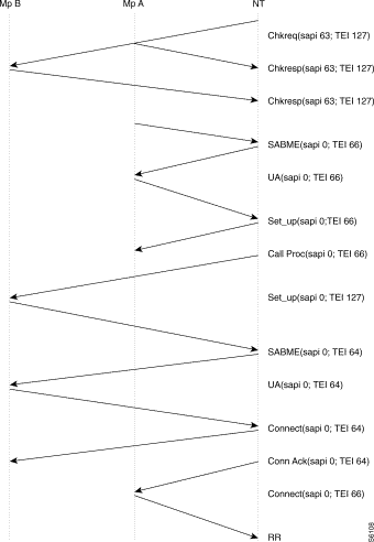
Both devices A and B have been already connected to the bus and the network checks the TEI assignment with a Check-Request. Devices A and B answer with respectively TEI 66 and 64. A wants to reach B and sends an outgoing Set-up. There is a incoming broadcast Set-up. B detects that this Set-up is for it and establishes the Data Link Level for answering the NT. The next two pages are a screen capture of this exchange.
**** HP 4952 Printer Output ****
SAPI TEI FType Q921 Ty Q931 Msg *
63 127 UI ChkReq *
FF00000F *
EF3F004F *
63 127 UI ChkRes
FF002808
CF3F7151
63 127 UI ChkRes
FF000F08
CF3F2E55
0 66 SABME
087
05F
0 66 UA *
087 *
053 *
0 66 INFO SETUP
08000000008992086083333333360853
050081154280E410C9046299390D3001
0 66 RR *
0800 *
0512 *
0 66 INFO CALL PROC*
08000080108 *
25028112819 *
0 66 RR
0800
2512
0 127 UI SETUP *
0F000000089108608333333336028333*
2F381154280812C9046299390CB03146*
0 64 SABME
087
01F
0 64 UA *
087 *
013 *
0 64 INFO CONNect
080000809208
01008117E410
0 64 RR *
0800 *
0112 *
0 64 INFO CONN ACK *
08000000 *
2102811F *
0 64 RR
0800
2112
0 66 INFO CONNect *
08000080 *
25228117 *
0 66 RR
0800
2514
0 64 RR *
0800 *
2113 *
This service offered by the Telecom companies provides a point-to-point connection, a so-called Permanent Logical Link (PLL), between the BRI and the Packet Handler (PH). The PH can route any X.121 call request coming from a BRI or PSPDN subscriber.
 X.25 Packet Switching on D-channel
Several PLL can be defined on BRI, up to four in France and up to eight in Spain. But only 9,6Kb/s of the D-channel's bandwidth, which is 16kb/s, can be used for PLL's.
Users must subscribe to this service and a PLL is defined as followed:
In fact, each PLL is like a PSPDN access multiplexed on BRI. On D-channel the frame format is:
LAPD | X25 | DATA | FCS |
The Service requested is Packet Mode on D, so the Service Access Point must be identified and the corresponding SAPI's value is 16.
Before being processed by the PH, each frame passes through the Frame Handler. The FH will do the translation between the two different Data Link Levels.
This kind of connection is useful for transactional applications.
On the FastPad the routing function uses the line number to know which one it must send a call on. That is why a PLL is always linked to a Virtual Line. The virtual line uses a X.25 profile which follows the X.25 service parameters defined at subscription.
As mentioned previously, a BRI can provide several PLL. Parameter 43 in the ISDN profile (47) defines the number of PLL for one S0 interface connection. This parameter refers to numbers of TEI by SAPI 16. Numbers of TEI because one PLL has its own TEI defined at the subscription and SAPI 16 to identify the SAP. Figure 6-76 shows how PLL connection can be represented on the FastPad.
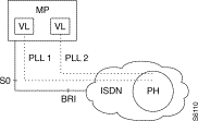
After that the number of PLL to use on a S0 has been set, each PLL must be fully defined. For that, an extension profile is used in class 13 of the port used for the D-channel. This profile is also number 47. The PLL's connections are managed by a function called DLM, which stands for Dynamic Line Management. It is necessary to activate this function in class 3 rec 15.
Within this profile each PLL is identified by:
The structure of profile 47 in C13 is the following:
Where n corresponds to the number of PLL defined according to the value of parameter 43.
The following example illustrates an mp having two PLL accesses on an S0 connection.
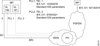 mp with Two PLL Accesses on an SO Connection
Here, no B-channel can be used on the S0 access. To reach the mp, located in Paris, the first choice is over PLL1 and PLL2 is the back-up. The configuration is the following (Table 6-39)
Class 12 rec 0 | Class 13 Rec 0 | Class 30 rec 0 | Class 30 rec 1 |
0 47 1 43,2 2 PLL 2 56,0 no B-channel
| 0 47 2 160 VL 3 1 TEI of PLL1 4 0 Rec 0 in C30 10 161 VL 11 2 TEI of PLL2 12 1 REC 1 in C30 | 0 0 PSPDN profile 1 53,0 Raw 0 in C10 2 45,2 2 @ mode
| 0 0 1 53,1 Raw 1 in C10 2 45,2
|
Class 10 rec 0 | Class 9 rec 0 | Class 9 rec 0 | Class 3 rec 15 |
0 12345678 1 87654321 | 0 192 | 0 4,2,0,160,161 | 0 1,GL |
The PLL setting phase can be established in two ways. At start-up or upon an incoming or outgoing call request.This choice is made according to parameter 70. If set to zero, it means at start-up, if set to one it means upon outgoing or incoming call request.
The setting phase diagram (Figure 6-78) is as follows:
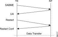
The PLL remains in Data Tansfer Mode.
However, there is an option that makes the PLL be a Half Permanent Logical Link. For that, there is time-out. This is parameter 69 (1-250s). When there is no more switched virtual circuit established, the PLL is in disconnect mode, as shown in Figure 6-79.
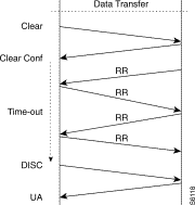
When 69 is set to 0, the timer is not activated. If 69 is not set to zero, parameter 70 will must be set to one.
In case of an ISDN S0 interface, only loop L0 on D-channel can be tested.
On a B-channel, the loop tests can not be used.
The syntax is T LIxx B0 where xx corresponds to the D-channel.
It is also possible to use the disconnect and disconnect option.
The syntax is T LIxx D or T LIxxC.
Ex:
*90006899D12MM
COM
CALL CONNECTED
T LI00D
9000 680A 2D0F 11B5 B11A FF0C 0000 0000 0000 0000 0000 0000 0000 0000 0000
TEST ENDED WITH NO ERROR
T LI00C
9000 680A 2D65 11B5 B11A FF0C 0000 0000 0000 0000 0000 0000 0000 0000 0000
TEST ENDED WITH NO ERROR
To test a switched connection or back-up solution, there is the possibility to open a connection by using this command: CIyyX@X.121
Ex: to reach node 8000 towards S0 access on port 0.
CI00X80000099
9000 0010 24C4 117F B142 FF0C 0000 0000 0000 0000 0000 0000 0000 0000 0000
TEST ENDED WITH NO ERROR
On D-channel EI / HI . In the display EI 000 is shown for a connection with B-channels and EI xxx if packet mode on D used, where xxx indicates the sum of all Svc established on PLL's.
On B-channels EI / HI.
Example 1 shows a connection within one B-channel.
Example 2 shows a connection on D-channel.
Example 1
*90006899D14SS
COM
CALL CONNECTED
I
EQT No : 900068
D: 29/05/92 H: 09/38/14
BUFC:5215
BUFF:4814
COM : 0001
PKTS SWITCHED:0001
FR SWITCHED : 0000
PROG:V 11.1.1.05
CONF:V 26
MODULE STATE M0:ES-OP M1:HS M2:HS
LINE STATE AND NO. OF LCS
00 EI 000 01 EI 001 02 HI 03 ES 000
04 NC 05 HA 06 NC 07 NC
08 NC 09 NC 10 NC 11 NC
12 NC 13 NC 14 NC 15 NC
16 NC 17 NC 18 NC 19 NC
20 NC 21 NC 22 NC 23 NC
24 NC 25 NC 26 NC 27 NC
28 NC 29 NC 30 NC 31 NC
32 NC 33 NC 34 NC 35 NC
Example 2
*90006899D14SS
COM
CALL CONNECTED
I
EQT No : 900068
D: 29/05/92 H: 09/38/14
BUFC:5215
BUFF:4814
COM : 0001
PKTS SWITCHED:0001
FR SWITCHED : 0000
PROG:V 11.1.1.05
CONF:V 26
MODULE STATE M0:ES-OP M1:HS M2:HS
LINE STATE AND NO. OF LCS
00 EI 001 01 HI 02 HI 03 HS
04 NC 05 HA 06 NC 07 NC
08 NC 09 NC 10 NC 11 NC
12 NC 13 NC 14 NC 15 NC
16 NC 17 NC 18 NC 19 NC
20 NC 21 NC 22 NC 23 NC
24 NC 25 NC 26 NC 27 NC
28 NC 29 NC 30 NC 31 NC
32 NC 33 NC 34 NC 35 NC
Observation on the D-channel is possible. Example 1 is an observation of a connection over ISDN using B-channels. Example 2 is for a connection in packet mode using D-channel.
On B-channels, it is like an X.25 line.
On a Virtual Line, it is like an X.25 line
Example 1:
*70001099D04OO0099
COM
CALL CONNECTED
7000 1009 7DA4 16CA B10B FF04 0000 0008 FCFF 030F 6B46 01FF
7000 1009 7DA4 16CA B10B FF04 0001 0008 FEFF 030F 6B46 0283
7000 1009 7E19 16CA B10B FF04 0000 0003 0083 7F
7000 1009 7E19 16CA B10B FF04 0001 0003 0083 73
7000 1009 7E19 16CA B10B FF04 0000 0042 0083 0000 0801 0105 A104 0288 9018 0183
6C0A 2180 3436 3239 3933 3930 6D06 8050 3139 3638 7009 8134
7000 1009 7E1A 16CA B10B FF04 0001 0004 0083 0102
7000 1009 7E1D 16CA B10B FF04 0001 000B 0283 0002 0801 8102 1801 8A
7000 1009 7E1D 16CA B10B FF04 0000 0004 0283 0102
7000 1009 7E25 16CA B10B FF04 0001 0008 0283 0202 0801 8107
7000 1009 7E25 16CA B10B FF04 0000 0004 0283 0104
7000 1009 7E89 16CA B10B FF04 0001 0004 0283 0103
7000 1009 7E89 16CA B10B FF04 0000 0004 0283 0105
7000 1009 7EB1 16CA B10B FF04 0001 0008 FEFF 030F 41C6 0287
7000 1009 7EED 16CA B10B FF04 0001 0004 0283 0103
7000 1009 7EED 16CA B10B FF04 0000 0004 0283 0105
7000 1009 7F51 16CA B10B FF04 0001 0004 0283 0103
7000 1009 7F51 16CA B10B FF04 0000 0004 0283 0105
7000 1009 7FB5 16CA B10B FF04 0001 0004 0283 0103
7000 1009 7FB5 16CA B10B FF04 0000 0004 0283 0105
7000 1009 8019 16CA B10B FF04 0001 0004 0283 0103
7000 1009 8019 16CA B10B FF04 0000 0004 0283 0105
7000 1009 807D 16CA B10B FF04 0001 0004 0283 0103
7000 1009 807D 16CA B10B FF04 0000 0004 0283 0105
7000 1009 80BE 16CA B10B FF04 0001 001E 0283 0402 0801 8145 0802 8790 2007 0032
342A 0100 0020 0700 3438 2A00 0000
7000 1009 80BE 16CA B10B FF04 0000 0004 0283 0106
7000 1009 80BE 16CA B10B FF04 0000 000C 0083 0206 0801 014D 0802 80E3
7000 1009 80BE 16CA B10B FF04 0001 0004 0083 0104
7000 1009 80C1 16CA B10B FF04 0001 000C 0283 0604 0801 815A 0802 8790
7000 1009 80C1 16CA B10B FF04 0000 0004 0283 0108
7000 1009 80C1 16CA B10B FF04 0001 0003 0283 53
7000 1009 80C1 16CA B10B FF04 0000 0003 0283 73
Example 2
90000099D04OO0099
COM
CALL CONNECTED
9000 000C 18E3 1176 A209 FF04 0080 0003 4003 7F
9000 000C 18E4 1176 A209 FF04 0081 0003 4003 73
9000 000C 18E4 1176 A209 FF04 0080 0009 4003 0000 1000 FBC7 00
9000 000C 18E4 1176 A209 FF04 0081 0009 4203 0002 1000 FB07 99
9000 000C 18E4 1176 A209 FF04 0080 0004 4203 0102
9000 000C 18E4 1176 A209 FF04 0080 0021 4003 0202 1004 0B2B 1932 0145 9990 5008
02AA 4207 0743 0203 0100 0000 3030 4747 4D
9000 000C 18E5 1176 A209 FF04 0081 0004 4003 0104
9000 000C 18E6 1176 A209 FF04 0081 0021 4203 0204 1001 0BB2 9919 3201 4590 5008
02AA 4208 0843 0202 0100 0000 3030 4747 4D
9000 000C 18E6 1176 A209 FF04 0080 0004 4203 0104
9000 000C 18E6 1176 A209 FF04 0080 0011 4003 0404 1001 0F00 0802 AA42 0707 4302
02
9000 000C 18E6 1176 A209 FF04 0081 0004 4003 0106
9000 000C 18E7 1176 A209 FF04 0081 0011 4203 0406 1004 0F00 0802 AA43 0203 4207
07
9000 000C 18E7 1176 A209 FF04 0080 0004 4203 0106
9000 000C 18ED 1176 A209 FF04 0081 0008 FEFF 030F 0000 04FF
9000 000C 18ED 1176 A209 FF04 0080 0009 FCFF 030F 0ABD 0586 03
9000 000C 194B 1176 A209 FF04 0081 0004 4203 0107
9000 000C 194B 1176 A209 FF04 0080 0004 4203 0107
9000 000C 1993 1176 A209 FF04 0080 0009 4003 0606 1004 1300 80
9000 000C 1993 1176 A209 FF04 0081 0004 4003 0108
9000 000C 1994 1176 A209 FF04 0081 0007 4203 0608 1004 17
9000 000C 1994 1176 A209 FF04 0080 0004 4203 0108
9000 000C 1994 1176 A209 FF04 0081 0009 4203 0808 1001 1300 80
9000 000C 1994 1176 A209 FF04 0080 0004 4203 010A
9000 000C 1994 1176 A209 FF04 0080 0007 4003 080A 1001 17
9000 000C 1994 1176 A209 FF04 0081 0004 4003 010A
9000 000C 19F8 1176 A209 FF04 0081 0004 4203 010B
9000 000C 19F8 1176 A209 FF04 0080 0004 4203 010B
9000 000C 1A28 1176 A209 FF04 0080 0003 4003 53
9000 000C 1A29 1176 A209 FF04 0081 0003 4003 73
Family 12.
Line level from event 00 to 0E: 02 S0 is activated; 03 is deactivated; 00 S0 in service; 01 S0 out of order.
LAP-D from event 30 to 4F: 4E to indicate S0 is within a bundle.
Command management 90 to B2: B0 a B-channel is disconnected; B1 a B-channel is connected (locally initiated); B2 a B-channel is connected (remote request).
D-protocol 60 and an appendix D (within the configuration manual)
The status of an S0 interface in terminal mode (TE) is numbered from F1 up to F8, it concerns the D-channel.
These states are coded in BCD (binary coded decimal) on the Led 105(1), 106(2), 107(4), 108(8).
They have the following meanings:
F1: inactive; no connection to network.
F2: detection of the energy source.
F3: inactivation; following detection.
F4: waiting for a signal.
F5: input identification.
F6: synchronization.
F7: activation; data transfer state.
F8: frame locking lost.
For the B-channels, it is like for X.25.
The FastPad can be connected to a packet switching network and to a circuit switching network. There are three connection possibilities:
EBS: Synchronous Standardized Input. An X.25 subscriber is connected across the switching circuit network to the FastPad. Only incoming X.25 calls are accepted. The modem operates in automatic answering mode.
 Modem Operation
 Modem Operation
Conversion of the numeration between the FastPad and the PSTN is necessary.
These services offer many applications.
Note the following two examples:


Wth the FastPad three different possibilities are offered on PSTN trunk connections. The purpose of the PSTN function is to provide a back-up solution. This function can be used with others like MLP or DLM. For more details refer to "Backup/Overflow/Dynamic Line Management (DLM)" in Chapter 7.
Profile in class 12 are used for the data transfer phase whereas those in Class 13 define behavior during the command mode period
In command mode, one can choose between V.25 bis and Hayes. An explanation of the configuration will be done with two examples and the command diagrams.
Synchronous PSTN stack 108/2 can also be used to allow remote users using X.25 to enter the network.
Since a PSTN network does not provide the calling address, ITU-T has defined a recommendation called X.32. This is a procedure specially based on XID exchange. This exchange take place before the LAP-B establishment.
This procedure can be handled by the modem itself or by the FastPad.
Another option is to use the facility offered by the address translation. In that case, an X.25 call will be accepted only, and only if the calling address is defined within the translation table. This option is not particular to PSTN but is a way to secure the access to the network especially if X.32 or CUG are not used.
The following 2 cases illustrate how, in a general way, what it is possible to do with the synchronous PSTN and the FastPad.
Diagrams in command mode
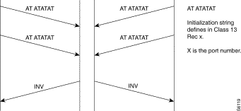

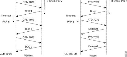
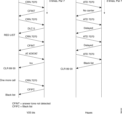
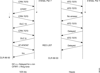
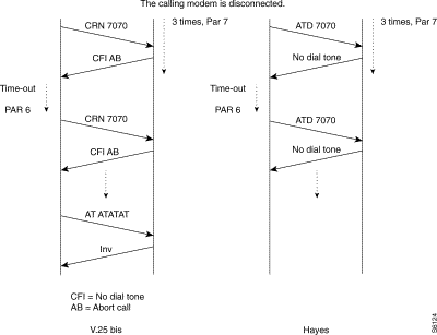
Outstanding events
The same as for X.25.
Maintenance (V54)
To get line status, use the following syntax: T LSxxS.
xx represents the line number.
It is possible to make the different loop defined within the V54 requirements.
There are: B0 or local interface loop (no control through the DB25)
B2 or remote interface loop (with RIL(140) and TI (142).
B3 or local line loop (with LL(141) and TI(142).
The syntax is: T LSxxBy xx is the line number
y is the loop type.
X.32
The X.32 ITU-T recommendation is used in a circuit switch network such as PSTN, ISDN to secure access to the private network or system and to identify the calling party.
Interworking between CSPDN and PDN network uses this procedure. A remote user will establish a connection with a PDN subscriber through a PSTN network using X.32.
The identification procedure is based on the exchange of XID frames, which take place before the establishment of the Data Link Layer. There are:
See section XID Frame format
The behavior during the identification phase is for:
The calling part, like for a DTE.
The called part, like for a DCE.
The level one Identification Procedure is executed when the Data Link Layer is in Disconnect Mode, as follows:
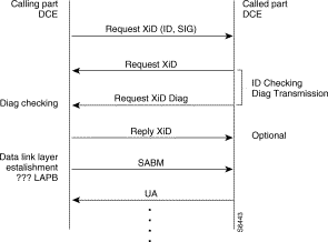 Level One Identification Procedure When Data Link Layer in Disconnect Mode
When the DIAG is positive, the Data Link Layer establishment starts-up, otherwise the physical PSTN connection is disconnected.
When the Data Link Layer is up any incoming XID frame is ignored.
The XID reply to the XID DIAG is optional and the calling party can directly answer with a SABM frame.
When there is no answer to a transmitted XID frame, the time-out and retransmission of LAP(N2*T1) is used. After N2 retries the physical PSTN connection is disconnected.
Fastpad allows Both XID frame formats (X.32 and Teletex).
As a calling party, it always answers with a XID reply to a XID DIAG.
As a called party, it answers with a positive DIAG and accepts a XID reply or SABM as acknowledgment.
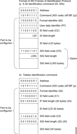
There will be a mapping table as for ISDN. In this case, both sites can initiate and accept a call (See Figure 6-92)
The SVC function can also to be used if the PSTN line does not belong to a bundle (see "Backup/Overflow/Dynamic Line Management (DLM)" in Chapter 7 and that user wants to have a transparent back-up solution without loosing the current session.

When the leased line (LL) fails, the PSTN backup line is established from mp 900010, when receiving a call request packet for a destination on mp 900020. A dialing command is automatically sent to the modem (Hayes or V.25bis command). Only one side is configured to initiate the backup.
If the Dynamic Line Management (DLM) feature is configured, the PSTN line is automatically disconnected when the leased line is restored.
If the Multi-Link Protocol (MLP) is used in conjunction with the DLM function, the virtual circuits are not cleared during the backup/restore time.
An initialization string must be defined in Class 20 Rec 0. The parameter 9 in the connection profile is an index which specifies which string to use.
ConfigurationTable 6-40 shows the configuration of the above example.
900010 | 9 00020 |
CLASS 1 RECURRENCE 1 | |
0 1 X.25 3 1 X.25 3 1 X.25 | 0 1 X.25 |
CLASS 12 RECURRENCE 0 | |
0 4 X.25 | 0 5 X.25 |
CLASS 12 RECURRENCE 3 | |
0 40 X.25 | 0 41 X.25 |
CLASS 13 RECURRENCE 3 | |
0 40 X.25 Default values (V10.1) 1 1 V.25bis asynchronous modem 2 2 108/2 call mode (addressed mode) 3 180 Supervision timer (x 1 sec) 4 10 Inactivity timer (x 10 sec) 5 10 Modem data rate in command mode 6 3 Call retry timer (x 1 sec) 7 3 Call retries 8 2 Outgoing call 9 1 Row of modem initialization string in class 20 10 0 XID frame on transmission 11 0 XID frame on reception 12 1 13 1 | 0 40 X.25 Default values (V10.1) 1 1 V25bis asynchronous modem 2 2 108/2 call mode (addressed mode) 3 180 Supervision timer (x 1 sec) 4 10 Inactivity timer (x 10 sec) 5 10 Modem data rate in command mode 6 3 Call retry timer (x 1 sec) 7 3 Call retries 8 1 Incoming call 9 1 Row of modem initialization string in class 20 10 0 XID frame on transmission 11 0 XID frame on reception 12 1 13 1 |
CLASS 20 RECURRENCE 0 | |
0 AAAAT Modem initialization string | 0 AAAAT Modem initialization string |
CLASS 22 RECURRENCE 0 | |
0 900020 X25 remote address | Not used on called side |
CLASS 22 RECURRENCE 1 | |
0 7070 PSTN remote number | Not used on called side |
CLASS 22 RECURRENCE 2 | |
0 30,00,00 Backup behavior (PSTN outgoing call) | Not used on called side |
CLASS 9 RECURRENCE 2 | |
0 20 Known ZO number | 0 10 Known ZO number |
CLASS 9 RECURRENCE 3 | |
0 4,2,0,0,3 Routing for ZO number 20 | 0 4,2,0,0,3 Routing for ZO number 10 |
In this mode, the modem is in charge of dialling over PSTN. The number is stored inside the modem.
In this case, mp's ports do not accept an incoming call.
This mode can be used for hierarchical and security aspects in the network.
The following example (Figure 6-93) illustrates this case.
 Example
When the leased line (LL) fails, the PSTN backup line is established from the mp 900010, when receiving a call request packet for a destination on the mp 900020. When the mp raises the DTR control signal, the modem automatically dials a stored PSTN number (Nº 7070 in this example). Only one side is configured to initiate the backup.
When using the 108/1 call procedure, no parameter is configured in class 22. No X.121 addresss is mapped to a particular PSTN number. The 108/1 call procedure cannot be configured to accept incoming call (Parameter 8 in class 13). Therefore, the 108/2 call procedure is configured on the called side.
If the Dynamic Line Management (DLM) feature is configured, the PSTN line is automatically disconnected when the leased line is restored.
If the Multi-Link Protocol (MLP) is used in conjunction with the DLM function, the virtual circuits are not cleared during the backup/restore time.
Table 6-41 shows the configuration.
900010 | 900020 |
CLASS 1 RECURRENCE 1 | |
0 1 X.25 3 1 X.25 | 0 1 X.25 3 1 X.25 |
CLASS 12 RECURRENCE 0 | |
0 4 X.25 | 0 5 X.25 |
CLASS 12 RECURRENCE 3 | |
0 40 X.25 | 0 41 X.25 |
CLASS 13 RECURRENCE 3 | |
Default values (V10.1) 1 1 V25bis asynchronous modem 2 2 108/2 call mode (addressed mode) 3 180 Supervision timer (x 1 sec) 4 10 Inactivity timer (x 10 sec) 5 10 Modem data rate in command mode 6 3 Call retry timer (x 1 sec) 7 3 Call retries 8 2 Outgoing call 9 1 Row of modem initialization string in class 20 10 0 XID frame on transmission 11 0 XID frame on reception 12 1 13 1 | 0 41 X.25 Default values (V10.1) 1 1 V25bis asynchronous modem 2 2 108/2 call mode (addressed mode) 3 180 Supervision timer (x 1 sec) 4 10 Inactivity timer (x 10 sec) 5 10 Modem data rate in command mode 6 3 Call retry timer (x 1 sec) 7 3 Call retries 8 1 Incoming call 9 1 Row in c 20 10 0 XID frame on transmission 11 0 XID frame on reception 12 1 13 1 |
CLASS 20 RECURRENCE 0 | |
0 AAAAAAAAAT Modem initialization string | 0 AAAAAAAAAT Modem initialization string |
CLASS 9 RECURRENCE 2 | |
0 20 Known ZO number | 0 10 Known ZO number |
CLASS 9 RECURRENCE 3 | |
0 4,2,0,0,3 Routing for ZO number 20 | 0 4,2,0,0,3 Routing for ZO number 10 |
Overview Configuration
Class 1 Rec 1
value
1 synchronous
Class 12 Rec x X physical line number
connection profile
40 DTE backup by V.25 bis or Hayes modem
41 DCE backup by V.25 bis or Hayes modem
Class 13 Rec x
extension profile
40 incoming/outgoing call
41 incoming call
42 incoming/outgoing + XID
43 incoming + XID
Class 22 Mapping table & behavior
rec0 X.121 address
rec1 PSTN number
rec2 behavior
is must be : 30,00,00
30 for in & out call
00 for reserved.
Class 20 Rec 0 Initialization string table
Class 201Rec 0-3 XID frame table
The following concerns the service parameters for the extension profile used in Class 13.
1 1, V25bis 2,hayes
2 1,direct (108/1) 2,addressed mode(108/2)
3 Supervision timer(1-250)*1s Time within which the PSTN connection must be established.
4 Inactivity timer(0-250)*10s, When this timer expires the PSTN is disconnected.
5 Modem rate in Command mode
6 Time-out between each PSTN dial-up attempt.
7 Numbers of dial-up attempts
8 1, incoming call, 2, incoming/outgoing call
9 index in class 20 rec0 for the initialization string.
10 transmit of XID frame. Rec x in C21
11 reception of XID frame
12 number of XID attempts by the remote.
13 reference values for the inactivity timer 0=1s 1=10s
Value assigned to 6 times value assigned to 7 must be less than value assigned to 3.
(6*7)'s values < 3's values.
It is possible to connect equipment of the type SNA to an X.25 network. SNA (System Network Architecture) is a system introduced by IBM.
The FastPad assures the transport of the SDLC protocol (SNA, level 2) in the X.25 network.
The implementation of that transport is in accordance with the one accepted by IBM. This means that a "Logical Link Control" layer (LLC) is used under SDLC to transport the controller information.
There are two LLC protocols available:
That is why it is possible to have, for example, on one side a cluster controller (SNA node, type T2.0 or T2.1) connected in SDLC to a FastPad and on the other side an SDLC host (SNA node, type T4) or X.25-NPSI.
Figure 6-94 shows an example of the standard architecture for this type of network

To assure the transport of this protocol there are two types of interfaces available in the FastPad:
This interface is intended to connect an IBM front-end Host computer (primary SNA node). It is called "SDLC Front-end". It can emulate a multipoint controller connection. The profile available for this type of interface is:
This interface is intended to connect the terminal controllers (Clusters; secondary SNA nodes). It is called "SDLC Remote". Each interface of this type can serve several multipoint controllers.
The profile available for this type of interface is:
In a configuration using a remote attachment via an mp's private network, the SNA traffic is carried via X.25 Switched Virtual Circuits (see Figure 6-95). Two standard protocols are used over X.25:
All X.25 data packets carrying SNA traffic contain a two-byte header followed eventually by SNA data. Two types of PSH messages are exchanged:
Control messages : Used for Mode Setting/Resetting procedures. These messages are identified as PS-CONTACT, PS-DISC, PS-XID, PS-TEST.
Data messages : Carry the actual SNA data to be transferred.
X.25 data packets carrying SNA traffic do not contain any particular header. The following control packets are exchanged with the Qualified (Q) bit set: QXID, QSNRM, QUA, QDISC.
They are used for Mode Setting/Resetting procedures.
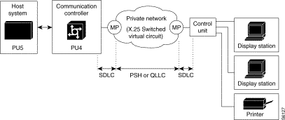 \xfa
\xfa
An X.25 adaptation is provided on SNA PU4 and PU2 nodes for remote attachment. It is therefore possible to connect such types of SNA nodes to X.25 public or private networks. Permanent Virtual Circuits (PVC) or Switched Virtual Circuits (SVC) are used for that purpose.
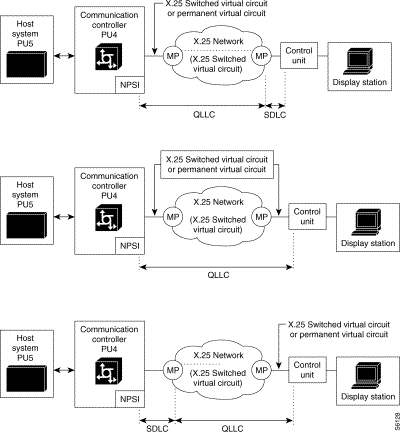
This section describes some configuration examples of SNA remote attachments via an mp's network.
The following case studies are shown:
Figure 6-97 shows an SDLC remote attachment between PU4 and PU2.0 SNA nodes via a private mp's network.

Figure 6-98 shows the data link control messages exchanged to set up the Normal Response Mode. After this, the Mode Setting phase exchange of information can take place. An X.25 call is placed by the mp which faces to the PU2.0 when the latter responds to a UA to the initial SNRM poll of the mp. The exchange of the XID-command between PU4 and PU2.0 is optional and may be skipped. The mp is able to respond to the XID-command in case the PU2.0 is not able to do so.
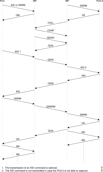
 Example
c1,r1 ( type of the link) | c1,r1 |
1 4 | 1 4 |
c12,r1 (service parameters) | c12,r1 |
0 18 ( primary sdlc profile) 1 1,16 (PU2.0 emulation) 2 28,10 (data rate 9600b/s) 3 46,1 (subsriber number) 4 90,1 (number of cluster) 5 91,1 (Row of the first cluster in c19r0)
default values P29,3 (frame size = 384 bytes) P32,50 (T1, no answer timer, time 100ms) P34,10 (N2, retry counter) P35,7 (K,frame window) P41,1 (QLLC protocol) P62,8 (Tx-packet size=256) P63,8 (Rx-packet size)
| 0 17 ( secondary sdlc profile) 1 1,17 (PU4 emulation) 2 28,10 (data rate 9600b/s) 3 46,1 (subsriber number) 4 90,1 (number of cluster) 5 91,1 (Row of the first cluster in c19r0)
default values P29,3 (frame size = 384 bytes) P32,50 (T1, no answer timer, time 100ms) P33,1 (T0,polling timer,time 100ms) P34,10 (N2, retry counter) P35,7 (K,frame window) P37,200 (Polling counter) P41,1 (QLLC protocol) P62,8 (Tx-packet size=256) P63,8 (Rx-packet size) |
c19.r0 ( cluster @ table) | c19,r0 |
0 0,193 0: not used 193: cluster address in dec 1: Row of the X25 remote FastPad @ in c8r0 193: cluster @ in dec | 0 1,193 c8,r0 c8,r4 c9,r7 |
c8,r0 | c8,r4 |
| 0 90000001 |
c8,r0 | c8,r4 |
0 90000001
| 0,1 (call time-out retransmission * 10s) c9,r7 (routing for unknown DNIC) |
c9,r7 (routing for unknown DNIC) | c9,r7 |
0 1,1,0, <trunk #> | 0,1 (call time-out retransmission * 10s) |
Figure 6-100 shows a SDLC multipoint configuration with three remote PU2.0 nodes. Note that up to 8 cluster controllers may be remotely attached on one mp's line configured for SDLC multipoint operation.
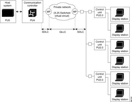
Figure 6-101 shows the data link control messages exchanged to set up the Normal Response Mode. Note that the Normal Response Mode is set for each PU2.0. If one of these fails to respond to the SNRM, it remains in Disconnected Mode. Another SNRM command is repeated periodically until the PU2.0 reacts with the UA response. In Figure 6-101 each PU2.0 has a specific data link address (C1, C2, C3). Figure 6-101 shows the timing between two successive polls for the cluster controller C2, before the reception of a QSNRM packet from the host and the adjacent RR polling for cluster controllers C1 and C3.
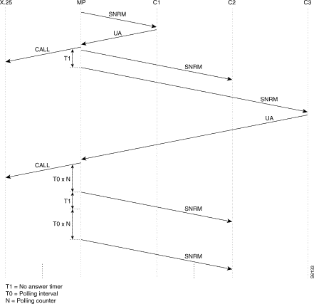
Figure 6-102 shows an SDLC remote attachment between PU4 and PU2.1 SNA nodes via a private mp's network.

The following illustrates an example of SDLC connection between a PU4 and a PU2.1
Figure 6-103 shows the data link control messages exchanged to set up the Normal Response Mode. In Figure 6-103 the PU2.1 cluster controller refuses the SNRM command by answering a DM response. Usually this is the case since the PU2.1 expects a XID command to start-up the data link. In general the first XID command of the PU4 is a report to the PU2.1, followed by 1 or 2 more XID commands before setting up the Normal Response Mode.
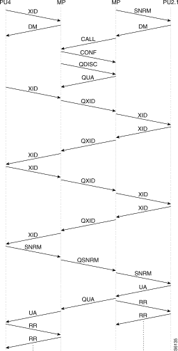
 Example
c1,r1 ( type of the link) | c1,r1 |
1 4 | 1 4 |
c12,r1 (service parameters) | c12,r1 |
0 18 ( primary sdlc profile) 1 1,20 (PU2.1 emulation) 2 28,10 (data rate 9600b/s) 3 46,1 (subsriber number) 4 90,1 (number of cluster) 5 91,1 (Row of the first cluster in c19r0)
default values P29,3 (frame size = 384 bytes) P32,50 (T1, no answer timer,time 100ms) P34,10 (N2, retry counter) P35,7 (K,frame window) P41,1 (QLLC protocol) P62,8 (Tx-packet size=256) P63,8 (Rx-packet size) | 0 17 ( secondary sdlc profile) 1 1,21 (PU4 emulation) 2 28,10 (data rate 9600b/s) 3 46,1 (subsriber number) 4 90,1 (number of cluster) 5 91,1 (Row of the first cluster in c19r0)
default values P29,3 (frame size = 384 bytes) P32,50 (T1, no answer timer,time 100ms) P33,1 (T0,polling timer,time 100ms) P34,10 (N2, retry counter) P35,7 (K,frame window) P37,200 (Polling counter) P41,1 (QLLC protocol) P62,8 (Tx-packet size=256) P63,8 (Rx-packet size) |
c19.r0 ( cluster @ table) | c19,r0 |
0 0,193 0: not used 193: cluster address in dec 1: Row of the X25 remote FastPad @ in c8r0 193: cluster @ in dec | 0 1,193 |
c8,r0 | c8,r0 |
| 0 90000001 |
c8,r4 | c8,r4 |
| 0,1 (call time-out retransmission * 10s) |
c9,r7 (routing for unknown DNIC) | c9,r7 |
0 1,1,0,<trunk #> | 0 1,1,0,<trunk #> |
SDLC protocol can also be used to connect two SNA PU4 nodes as shown in Figure 6-105. The Normal Response Mode is also used on such a type of connection. The role of Primary and Secondary station is usually negotiated after 2 or more XID frame exchanges.

Figure 6-106 shows the Normal Response Mode setting phase between the two PU4 nodes. Two or more XID frames are usually exchanged before the Primary station sends the SNRM command. Frames sent by the Secondary station have the MSB bit of the data link address set to '1'.
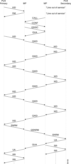
 Example
c1,r1 ( type of the link) | c1,r1 |
1 4 | 1 4 |
c12,r1 (service parameters) | c12,r1 |
0 18 ( primary sdlc profile) 1 1,25 (Secondary PU4 emulation) 2 28,10 (data rate 9600b/s) 3 46,1 (subsriber number) 4 90,1 (number of cluster) 5 91,1 (Row of the first cluster in c19r0)
default values P29,3 (frame size = 384 bytes) P32,50 (T1, no answer timer,time 100ms) P34,10 (N2, retry counter) P35,7 (K,frame window) P41,1 (QLLC protocol) P62,8 (Tx-packet size=256) P63,8 (Rx-packet size) | 0 17 ( secondary sdlc profile) 1 1,26 (Primary PU4 emulation) 2 28,10 (data rate 9600b/s) 3 46,1 (subsriber number) 4 90,1 (number of cluster) 5 91,1 (Row of the first cluster in c19r0)
default values P29,3 (frame size = 384 bytes) P32,50 (T1, no answer timer,time 100ms) P33,1 (T0,polling timer,time 100ms) P34,10 (N2, retry counter) P35,7 (K,frame window) P37,200 (Polling counter) P41,1 (QLLC protocol) P62,8 (Tx-packet size=256) P63,8 (Rx-packet size) |
c19.r0 ( cluster @ table) | c19,r0 |
0 0,193 0: not used 193: cluster address in dec 1: Row of the X25 remote FastPad @ in c8r0 193: cluster @ in dec | 0 1,193 |
c8,r0 | c8,r0 |
| 0 90000001 |
c8,r4 | c8,r4 |
| 0,1 (call time-out retransmission * 10s) |
c9,r7 (routing for unknown DNIC) 0 1,1,0,<trunk #> | c9,r7 (routing for unknown DNIC) 0 1,1,0,<trunk #> |
The FastPad does not manage the negotiation for the primary function.
XID Polling timer value must be higher than T0 from the mp.
 Example
c1,r1 ( type of the link) | c1,r1 |
1 4 | 1 4 |
c12,r1 (service parameters) | c12,r1 |
0 18 ( primary sdlc profile) 1 1,22 (Secondary PU2.1 emulation) 2 28,10 (data rate 9600b/s) 3 46,1 (subsriber number) 4 90,1 (number of cluster) 5 91,1 (Row of the first cluster in c19r0)
default values P29,3 (frame size = 384 bytes) P32,50 (T1, no answer timer,time 100ms) P34,10 (N2, retry counter) P35,7 (K,frame window) P41,1 (QLLC protocol) P62,8 (Tx-packet size=256) P63,8 (Rx-packet size) | 0 17 ( secondary sdlc profile) 1 1,23 (Primary PU2.1 emulation) 2 28,10 (data rate 9600b/s) 3 46,1 (subsriber number) 4 90,1 (number of cluster) 5 91,1 (Row of the first cluster in c19r0)
default values P29,3 (frame size = 384 bytes) P32,50 (T1, no answer timer,time 100ms) P33,1 (T0,polling timer,time 100ms) P34,10 (N2, retry counter) P35,7 (K,frame window) P37,200 (Polling counter) P41,1 (QLLC protocol) P62,8 (Tx-packet size=256) P63,8 (Rx-packet size) |
c19.r0 ( cluster @ table) | c19,r0 |
0 0,193 0: not used 193: cluster address in dec 1: Row of the X25 remote FastPad @ in c8r0 193: cluster @ in dec | 0 1,193 |
c8,r0 | c8,r0 |
| 0 90000001 |
c8,r4 | c8,r4 |
| 0,1 (call time-out retransmission * 10s) |
c9,r7 (routing for unknown DNIC) 0 1,1,0,<trunk #> | c9,r7 (routing for unknown DNIC) 0 1,1,0,<trunk #> |
 Example
c1,r1 ( type of the link) | c1,r1 |
1 1 X.25 | 1 4 |
c12,r1 (service parameters) | c12,r1 |
0 1 (X.25 user line(DCE)) 1 2,0 ( Standard X.25) 2 5,2 (1st incoming) 3 9,2 (1st bothways) 4 11,0 (Nbr of bothways) 5 13,2 (1st outgoing) 6 28,10 (data rate 9600b/s) 7 32,30 (T1 = 3s) 8 33,10 (T2 = 1s) 9 35,7 (K = 7) 10 45,2 (mode 2 addresses) 11 48,0 (no CUG) 12 56,0 (no Throughput neg) 13 90,1 (Nbr of PVC) 14 91,1 (1st entry in C17R0) default values P29,2 (frame size = 256 bytes) P34,10 (N2, retry counter) P62,7 (Tx-packet size=128) P63,7 (Rx-packet size=128) P69,2 (Tx-window size) P70,2 (Rx-Window size) | 0 17 ( secondary sdlc profile) 1 1,19 (PU4 emulation) 2 28,10 (data rate 9600b/s) 3 46,1 (subsriber number) 4 90,1 (number of cluster) 5 91,1 (Row of the first cluster in c19r0)
default values P29,3 (frame size = 384 bytes) P32,50 (T1, no answer timer,time 100ms) P33,1 (T0,polling timer,time 100ms) P34,10 (N2, retry counter) P35,7 (K,frame window) P37,200 (Polling counter) P41,1 (QLLC protocol) P62,8 (Tx-packet size=256) P63,8 (Rx-packet size) |
c17r0 | c19,r0 |
0 0,1,1,1 0: not used 1 called side 1 local Lcn 1:remote Lcn
| 0 1,193 1: Row of the X25 remote FastPad @ in c8r0 |
| c8,r0 193: cluster @ in dec |
| c8,r0 0 90000001 |
| c8,r4 0,1 (call time-out retransmission * 10s |
| c9,r7 0 1,1,0,<trunk #> |
 Example
TCU @ = C1hex
c1,r1 ( type of the link) | c1,r1 |
1 1 X.25 | 1 4 |
c12,r1 (service parameters) | c12,r1 |
0 1 (X.25 user line(DCE)) 1 2,0 ( Standard X.25) 2 5,11 (1st incoming) 3 9,1 (1st bothways) 4 11,10 (Nbr of bothways) 5 13,1 (1st outgoing) 6 28,10 (data rate 9600b/s) 7 32,30 (T1 = 3s) 8 33,10 (T2 = 1s) 9 35,7 (K = 7) 10 45,2 (mode 2 addresses) 11 48,0 (no CUG) 12 56,0 (no Throughput neg)
default values P29,2 (frame size = 256 bytes) P34,10 (N2, retry counter) P62,7 (Tx-packet size=128) P63,7 (Rx-packet size=128) P69,2 (Tx-window size) P70,2 (Rx-Window size) |
0 17 ( secondary sdlc profile) 1 1,19 (PU4 emulation) 2 28,10 (data rate 9600b/s) 3 46,1 (subsriber number) 4 90,1 (number of cluster) 5 91,1 (Row of the first cluster in c19r0)
default values P29,3 (frame size = 384 bytes) P32,50 (T1, no answer timer,time 100ms) P33,1 (T0,polling timer,time 100ms) P34,10 (N2, retry counter) P35,7 (K,frame window) P37,200 (Polling counter) P41,1 (QLLC protocol) P62,8 (Tx-packet size=256) P63,8 (Rx-packet size) |
| c19,r0 |
| 0 1,193 1: Row of the X25 remote FastPad @ in c8r0 193: cluster @ in dec |
| c8,r0 0 90000001 |
| c8,r4 0,1 (call time-out retransmission * 10s) |
| c9,r7 0 1,1,0,<trunk #> |
Work Sheet
Project name: ..........................................................................................................
Customer @: ...........................................................................................................
Contact points: ........................................................................................................
Date: .......................................................................................................................
Objective:................................................................................................................
Diagram:.................................................................................................................
Node address:..........................................................................................................
Port number:............................................................................................................

1r1: type of line |
|
| C1r1: type of line |
|
|
port#>: 4 (sdlc type) |
|
| port#>: 4 (sdlc type) |
|
|
12r<port#>: | service parameter |
| C12r<port#>: | service parameter |
|
profile 18 for Primary sdlc |
| profile 17 for Primary sdlc |
| ||
P1 PU's type | 16 PU4 | 18 PU4 | P1 PU's type | 17 PU4 | 19 PU2.0,2.1 |
| 20 PU4 | 22 PU2.1 |
| 21 PU2.1 | 22 PU2.1 |
| 25 PU4 |
|
| 24 PU2.1 | 25 PU4 |
P16 Encoding type: |
| 0 NRZ 0 NRZI | P16 Encoding type: |
| 0 NRZ 0 NRZI |
P29 Frame size: |
|
| P29 Frame size: |
|
|
P32T1 (no answer time): |
| in steps of 100ms | P32T1 (no answer time): |
| in steps of 100ms |
P34 N2 (retry number): |
|
| P33TO (polling interval) |
| n steps of 100ms |
P35 K frame windows): |
|
| P34 N2 (retry number): |
|
|
P40 PSH segment: |
|
| P35 K frame windows): |
|
|
P41 Procedure type: |
| 0 PSH 1 QLLC | P40 PSH segment: |
|
|
P42 (# of calls transmitted): |
|
| P41 Procedure type: |
| 0 PSH 1 QLLC |
P46 Subscriber number: |
|
| P42 (# of calls transmitted): |
|
|
P62 Default packet size: |
|
| P46 Subscriber number: |
|
|
P90 Number of cluster: |
|
| P62, P63 Default packet size: |
|
|
P91 Row R of the first cluster in C19r0: |
|
| P90 Number of cluster: |
|
|
P40 PSH Encoding type: |
|
| P91 Row R of the first cluster in C19r0: |
|
|
P41 Encoding type: |
|
|
|
|
|
19r0: | Cluster @ table |
| C19r0: | Cluster @ table |
|
R-1>:0<cluster @ in Dec> |
|
| <R-1:0>cluster @ in Dec> |
|
|
P41 Encoding type: |
|
| C8r0: | X25 remote FastPAD address | |
|
|
| <Q-1>: | X25 address, X |
|
|
|
| C8r4: | Retransmission time-out | |
|
|
| <Q-1>: |
| in steps on 10 s |
|
|
| C8r2: | Xld transmission if need be | |
|
|
| <Q-1>: |
|
|
In SDLC, data between two Logical Stations is transmitted in the form of "frames". All information sent via the data link, including real data and control information, is put in a frame. A frame comprises the following fields (see Figure 6-102):

The different SDLC frame types are cataloged in three groups. These three groups apply to commands as well as to responses. These three groups are:
An overview of the possible commands and responses is given in Table 6-49.
CATEGORY | COMMANDS | RESPONSES | CONTROL FIELD
| HEX VALUE | ||||||||
|
|
| 7 | 6 | 5 | 4 | 3 | 2 | 1 | 0 | P/F = 1 | P/F = 0 |
I-FRAME | I |
| r | r | r | PF | s | s | s | 0 | even | even |
S-FRAME | RR | RR | r | r | r | P/F | 0 | 0 | 0 | 1 | x1 1 | x2 1 |
| RNR | RNR | r | r | r | P/F | 0 | 1 | 0 | 1 | x1 5 | x2 5 |
| REJ | REJ | r | r | r | P/F | 1 | 0 | 0 | 1 | x1 9 | x2 9 |
U-FRAME | SNRM |
| 1 | 0 | 0 | P | 0 | 0 | 1 | 1 | 93 | 83 |
| SNRME |
| 1 | 1 | 0 | P | 1 | 1 | 1 | 1 | DF | CF |
|
| DM | 0 | 0 | 0 | P/F | 1 | 1 | 1 | 1 | 1F | 0F |
| DISC | RD | 0 | 1 | 0 | P/F | O | O | 1 | 1 | 53 | 43 |
|
| UA | 0 | 1 | 1 | P | O | O | 1 | 1 | 73 | 63 |
| SIM | RIM | 0 | 0 | 0 | P/F | O | 1 | 1 | 1 | 17 | 07 |
| TEST | TEST | 1 | 1 | 1 | P/F | O | O | 1 | 1 | F3 | E3 |
| XID | XID | 1 | 0 | 1 | P/F | 1 | 1 | 1 | 1 | BF | AF |
| UI | UI | 0 | 0 | 0 | P/F | O | O | 1 | 1 | 13 | 03 |
|
| FRMR | 1 | 0 | 0 | F | O | O | 1 | 1 | 97 | 87 |
r = receive counter 1 odd number
s = send counter 2 even number
P = poll bit
F = final bit
Equipment of the type BSC 3270 can be connected to the FastPad. Configuration of BSC is governed by the software license (BSC).
The FastPad assures the local emulation of the character synchronous BSC 3270 procedure (BSC = Binary Synchronous Communication) and the transport of the data messages.
The FastPad network is transparent to the multipoint BSC link. Figure 6-113 gives the standard architecture for this type of network.
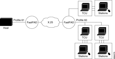
TCU | = | Terminal Controller Unit. |
Station | = | Terminal (screen or printer) |
To assure the data transport of this protocol, a virtual circuit is established between the two types of interface available on the FastPad equipment:
The interface, connecting the host interfaces, is called HPAD.
It emulates a multipoint connection of the controllers.
The available profile for this type of interface is:
This interface, connecting the terminal controllers, is called TPAD. Each interface of this type supports several controllers in a multipoint connection.
The available profile for this interface type is:
The address list for the terminals present on the BSC line must thus be configured in C13 profile 60 (predefined station address list).
Each terminal controller that wants to connect to a host, must know the X.25 address of the corresponding HPAD interface, to be able to establish a virtual circuit for each station or for each controller.
For this reason, the user must configure the controller address table in class 19 and the automatic calling table in class 8.
HPAD
| TPAD
| ||
Profile 61 | Profile 60 | ||
28 | Access rate | 28 | Access rate |
32 | No host polling timer | 33 | polling ? timer |
36 | type of coding | 34 | type of coding |
39 | WACK transmission if start print bit in WCC is turned on | 36 | WACK transmission if start print bit in WCC is turned on |
40 | ACK reply if no SVC |
|
|
41 | no reply timer | 41 | no reply timer |
42 | retry, reenter | 42 | retry, reenter |
62 | block length | 62 | block length |
46 | subscriber no. | 46 | subscriber no. |
37 | parity | 37 | parity |
35 | ingress queue depth | 35 | ingress queue depth |
90 | number of cluster | 90 | number of cluster |
91 | entry index in C19R0 | 91 | entry index in C19R0 |
C19R0 | ||
X | A, B, C, D | For each entry, there are four fields |
| A: Entry order in C8 (not significant for HPAD and set too) B: Cluster @ C: Number os stations behind the cluster D: Entry ingress of the first station in C13 Rx | |
| ||
| ||
Maximum number of clusters per port is 32.
Maximum number of stations per port is 32.
*(1) start print bit
(2) WCC write control character
(3) RVI reverse interrupt
(4) ITB Intere transmission block

C1, R1 | C1, R1 |
Par. 1 : 8 (line type = BSC) | Par. 1 : 8 (line type = BSC) |
C12, R1 | C12, R1 |
Profile : 61 Par. 28 : 6 (Data rate 2400 bit/s) Par. 32 : 6 (Host polling time out) Par. 40: 1 (Answer to poll/select only if VC exist) Par. 90 : 1 (Co. of cluster controllers) Par. 91 : 1 (Row of first cluster) Default values Par. 29 : 5 (BSC clock sie = 640 bytes) Par. 32 : 3 (Host polling time out) Par. 36 : 0 (EBCDIC code) Par. 62 : 10 (Tx packet size = 1024 bytes) Par. 63 : 7 (Rx packet size = 128 bytes, don't change) | Profile : 60 Par. 28 : 6 (Data rate 2400 bit/s) Par. 33 : 6 (mp polling interval) Par. 46: 1 (Answer to poll/select only if VC exist) Par. 90 : 1 (Co. of cluster controllers) Par. 91 : 1 (Row of first cluster) Default values Par. 29 : 5 (BSC clock sie = 640 bytes) Par. 33 : 3 (mp polling interval) Par. 36 : 0 (EBCDIC code) Par. 62 : 10 (Tx packet size = 1024 bytes) Par. 63 : 7 (Rx packet size = 128 bytes, don't change) |
C13, R1 | C13, R1 |
Profile : 60 | Profile : 60 |
C19, R0 | C19, R0 |
Par. 0 : 0 , 0 , 1 , 1
| Par. 0 : 0 , 0 , 1 , 1
|
C8, R0 | C8, R0 |
--- | Par. 0 : 9000 00 01 (Called address) |
C8, R4 | C8, R4 |
--- | Par. 0 : 1 (Called time-out retransmission) |
C9, R2 | C9, R2 |
Par. i : 10 (zone number) | Par. i' : 00 (Zone number) |
C9, R3 | C9, R3 |
Par. j : 1 , 1 , 0 , 0 (Routing for zone 10) | Par. i' : 1 , 1 , 0 , 0 (Routing for zone 00) |
C9, R4 | C9, R4 |
Par. i : 01 (Subscriber number) | Par. i' : 01 (Subscriber number) |
C9, R5 | C9, R5 |
Par. i : 1 , 1 , 0 , 1 (Routing for subscriber 01) | Par. i : 1 , 1 , 0 , 1 (Routing for subscriber 01) |
(*) Table in Chapter 9 "Extension Profile and Parameters" for complete survey of addresses.
Equipment of the type BSC 2780/3780 can be connected to the FastPad.
The FastPad assures the local emulation of the character synchronous BSC 2780/3780 procedure (BSC = Binary Synchronous Communication) and the transport of the data messages.
The FastPad network is transparent to the multipoint BSC link.
Figure 6-116 gives the standard architecture for this type of network.

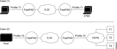
PSTN = Public Switched Telephone Network
CPU = Control Processor Unit
To assure the data transport of this protocol, a virtual circuit is established between the two types of interface, available on the FastPad equipment:
This interface connects the BSC 2780/3780 equipment that requests a transfer. With BSC 3780, it is possible to emulate several terminals via the PSTN; in that case the identification of the terminal must be managed.
The available profiles for these types of interfaces are:
This interface is used to connect the BSC 2780/3780 equipment that receives the transfer request. The identification of the terminal must be managed when the "calling" side connects several BSC 3780 terminals via the PSTN.
The available profiles are:
To enable the establishment of a virtual channel, it is necessary for the BSC 2780/3780 "calling as well as "called" side to know the X.25 address of the corresponding interface.
For that reason, the user must configure this in the "automatic calling table" (classes 8 and 19) and if the terminal identification must also be managed, they must be configured in class 13, profile 70.
The following diagram gives the steps in the configuration process of an SSC 2780/3780 line, using the standard profiles.
Additional parameters can be configured according to specific needs of the user.
Details of the parameters are described in Chapter 4.
 Configuration of a BSC 2780/3780 Line
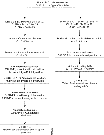
The transparent BSC (BSC-T) function is used to connect most variants of the BSC protocol through an X.25 network.
The chosen principle consists of detecting frames on the physical connection, packetizing them, directing them to an X.25 network, and transmitting them as they are to the remote BSC-T connection.
No local emulation of the BSC protocol takes place; hence there is no sensitivity to procedure variations and only the format of the frame must be recognized.
Similarly, cyclic redundancy is not checked, and is carried without transformation in order to optimize the processing time in the concentrator.
What remains then is to ensure the possibility of recognizing the frame formats of the varying BSC standard protocol. This is achieved by the configuration of class 13 which, within the limits of the adapted structure, enables the recognition of most BSC type frames.
The configuration of this class is of primary importance for frame recognition, as configuration errors could lead to non-recognition of certain frames or erroneous interpretations of frames resulting in truncated frames.
Profiles exist; their suitability for the connected protocol must simply be ascertained.
It is possible to depart from the values given in the profiles. It is recommended that the validity at a profile of a modification for a given case should be checked out with the Cisco user support department.
In any case, responsibility for the selection of profiles, or modifications in relation to profiles falls on the person making the configuration choices.
 BSC-T Connection in a Network
Two parts may be distinguished in the configuration of BSC-T connections:
These configurations follow the plan given in the block diagram below.
It is possible to modify the parameters of the connection given by the profiles, in Class 12 and 13.
Details about the parameters of Classes 12 and 13 are given in Chapter 4.
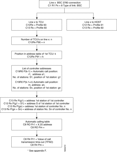
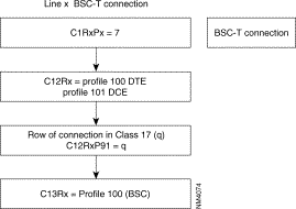
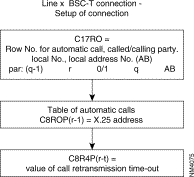 Line x BSC- T Connection
Main Frame Side: | |||
DNIC Z0 | : 200030 | C17, R0 P.V.C or LLP tables, 250P |
|
Port 01 |
| 0 1, 1, 0, 1 | |
C1 Configuration identification | C8 automatic call numbers | ||
C1, R1 type of lines, 42P | C8, R0 called address (16 char.), 200P 0 14401002 C8, R4 CALL retrans. time-out (200P), 0 1 | ||
1 | 7 | ||
C12 connection: synchronous parameters |
| ||
C12, R1 connection param. of line 2, 41P |
| ||
0 1 2 3 5 6 11 12 13 14 15 16 17 | 102 91,1 29, 16 28, 10 1, 2 33, 0 92, 0 20, 0 21, 1 24, 0 25, 1 26, 5 46, 1 | Reserved (profile) Position if connection (C17) NB of buffers/frame Interface clock rate Type of link Additional syns. One pad suppression I/O Interface status def. I/O Interface status def. Interface sign rec. Interface sign rec. Interface sign trans. No. of calling subscribe |
* 1 to 250
* 1 = DTE, 2 = DCE * 0 or 2 * 0 = No, 1 = yes * 8 = 105 * 8 = 105 * states defined * states defined * * |
C13 connection: extension parameters | |||
C13, R1 | extens. param. of line 2, 22/32P | ||
0 | 100 Reserved (profile) | ||
C17 P.V.C. or DLCI tables | |||
Remote Side: | |||
DNIC Z0 | : 144010 | C17, R0 P.V.C or LLP tables, 250P |
|
Port 02 |
| 0 1, 1, 0, 1 |
|
C1 Configuration identification | C8 automatic call numbers | ||
C1, R1 type of lines, 42P |
|
| |
2 | 7 |
|
|
C12 connection: synchronous parameters |
| ||
C12, R2 connection param. of line 2, 41P |
| ||
0 | 102 | Reserved (profile) |
|
1 | 91,1 | Position if connection (C17) | * 1 to 250 |
2 | 29, 16 | NB of buffers/frame | * 1 = 128 * 1 to 256 |
3 | 28, 10 | Interface clock rate | * 6 = 2400 8 = 4800 |
5 | 1, 2 | Type of link | * 1 = DTE, 2 = DCE |
6 | 33, 0 | Additional syns. | * 0 or 2 |
7 | 62, 11 | Def. pkt. size on trans. | * 5 = 32, 6 = 64 |
11 | 92, 0 | One pad suppression | * 0 = No, 1 = yes |
12 | 20, 0 | I/O Interface status def. | * 8 = 105 |
13 | 21, 1 | I/O Interface status def. | * 1 = 111, 2 = 140 |
14 | 24, 0 | Interface sign rec. | * states defined |
15 | 25, 1 | Interface sign rec. | * states defined |
16 | 26, 5 | Interface sign trans. | * |
17 | 46, 2 | No. of calling subscribe | * |
C13 connection: extension parameters | |||
C13, R2 | extens. param. of line 2, 22/32P | ||
0 | 100 Reserved (profile) | ||
C17 PVC or DLCI tables | |||
C17, R0 PVC or LLP tables, 250P | |||
0 | 1, 0, 0, 2 | ||
C8 automatic call numbers | |||
C8, R0 | called addresses (16 char.), 200P | ||
0 | 20003001 | ||
C8, R4 | CALL retrans. time-out, 200P | ||
0 | 1 | ||
OSI | BULL |
7 | application |
6 | DSA |
5 | |
4 | |
3 | |
2 | VIP |
1 | 1 |
Figure 6-123 illustrates the different components of a DSA Network.
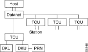
DSA: Distributed System Architecture.
Host: Main-frame such as Min6, DPS6000/7000.
Datanet: Front-end processor providing concentration and switching function.
TCU: Terminal Control Unit such as Questar F/T, Questar 1410/1420 ATM.
DKU: Display Keyboard Unit.
Station: DKU or DKU + printer.
Allows point-to-point and multipoint connections.
The data link procedure is Half-Duplex.
The coding type is ASCII 7bits plus ODD parity.
The checksum use the LRC method.
VIP is Character Oriented Protocol (COP) such as BSC from IBM.
Synchronization is done on SYN character.
Figure 6-124 illustrates a standard set-up.
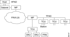
The FastPads locally emulate VIP protocol and does spoofing.
The port connected to the front-end processor is called HPAD.
The port connected to the remote side is called a TPAD.
Since there is spoofing, the network is transparent for the end devices. Only text messages pass through the network.
Direct lines, dedicated lines, PSTN (Datanet calls the HPAD, TCU calls the TPAD)
The Logical Link is done from the TPAD to the HPAD. As soon as the station answers to the polling, the TPAD will send the call request using automatic calling behavior.
HPAD |
| TPAD |
|
51 | connection profile number | 50 | connection profile number |
29 | frame size | 29 | frame size |
32 | interpolling timer | 32 | no reply polling timer |
33 | delay for ack printer | 33 | inter cycle polling timer |
35 | ingress queue depth | 34 | no reply polling counter |
37 | No EOT if NO cv | 35 | ingress queue depth |
39 | no reply screen messg timer | 39 | no reply screenmessg timer |
40 | no reply printer messg timer | 40 | no reply printer messg timer |
42 | retry counter for messg | 42 | retry counter for messg |
43 | local mgmt of printer messg | 43 | local mgmt of printer messg |
62 | message length | 62 | message length |
90 | number of polled addresses | 90 | number of polled addresses |
91 | 1st entry in c19r0 | 91 | 1st entry in c19r0 |
The extension profile number to use in Class 13 <port #> is : Profile 50
A maximum of 8 clusters per TPAD line
A Maximum of 32 stations per TPAD line.
Ex: a TCU with 8 stations each
1 TCU with 32 stations
Cluster/Station addresses are defined in C19R0.
C19R0
For each entry there are four fields (A,B,C,D)
row
x A,B,C,D
A: entry in C8 for the X.121 @ of the Hpad.
B: TCU @ or Station @ if polling station
C: number of stations attached behind the TCU. If 0, it means polling station.
D: Entry in C13.
The extension profile 50 used in C13Rx and contents VIP addresses.
Configuration example:

Access rate on HPAD is 19,2kb/s and 9,6kb/s on TPAD. TCU 1 behind the TPAD has three stations (addresses:1,2,3).TCU 3 behind the TPAD has 3 stations (addresses:5,6,27). There is a polling station for the address 27. Local management for printer is turned on. The HPAD does not answer to the host polling if there is no SVC. No reply polling timer (TPAD) is 1s. Message length up to 4Kb.
C1 R1
| |||||
1 6 VIP |
|
| 1 6 VIP | ||
C12 R1 | |||||
0 51 VIP connection profile HPAD | 0 50 VIP connection profile TPAD | ||||
1 28,11 19,2kb/s 2 29,32 for 4KB message 3 35,40 Ingress queue depth 4 37,0 No EOT answer if no SVC 5 43,1 Local mngt t for PRN messg 6 46,1 Subscriber number 7 62,12 messg length up to 4KB 8 90,3 Tree polling addresses 9 91,1 First entry in C19R0 | 1 28,10 9,6kb/s 2 29,32 for 4KB message 3 32,10 no reply polling timer 4 35,40 Ingress queue depth 5 43,1 Local mngt for PRN messg 6 46,1 Subscriber number 7 62,12 messg length up to 4KB 8 90,3 Tree poling addresses 9 91,1 First entry in C19R0 | ||||
other default values | |||||
32,30 interpolling timer time out 33,30 delay for ack printer 39,1 no reply screen messg timer 40,7 no reply printer messg counter 42,5 retry counter for messg | 33,3 inter cycle polling timer 34,6 no reply polling counter 36,0 polling type after a select 41,0 the transmit request is ignored 40,7 no reply printer messg counter | ||||
C13 R1 | |||||
0 50 VIP extension profile | 0 50 VIP extension profile | ||||
C19 R0 | |||||
0 1,1,3,2
| 1: First entry in C8 1: TCU 1 3: Tree stations behind TCU 1(polling cluster) 2: 2nd entry in C13R1 3: TCU 3 2: Two stations behind TCU 3(polling cluster) 6: 6th entry in C13R1 27: Station 27 0: Polling station 28: 28th entry in C13R1 | 0 1,1,3,2
1 1,3,2,6
2 1,27,0,28 |
|
| |
C8 R0
| |||||
0 90000001 TPAD calling address | 0 80000001 HPAD remote address | ||||
C8 R4
| |||||
0 0 no slow call | 0 1 slow call of 10 s | ||||
This function is the interface between the Asynchronous device procedure and the X.25 protocol. It meets the following requirements:
X.3 recommendation: specifies a set of 22 PAD parameters that determine how the PAD adapts the Asynchronous DATA stream from the DTE into X.25 packets and vice versa.
X.28 recommendation: describes the DTE/DCE interface between a synchronous DTE and a PAD such as: procedure to establish a call, to exchange data between the asynchronous device and a PAD, to exchange control information.
X.29 recommendation: defines the procedures for exchanging control information between a PAD and a remote PAD.

Figure 6-127 gives an overview of the different main connection profiles used.
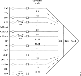
C14R0 is used to define a specific customer profile that does not follow X.3
recommendation. (Profile number 80).
Three possibilities are offered to do this.
1. addressed call:
The X.121 address is indicated by the terminal according to the X.2b recommendations.
* Presentation of a Network User Identifier (NUI)
Nxxxxxx- Called address or mnemonic. The NUI allows up to six characters and is not echoed
Ex: if the user NUI is "naoned" and the remote address is 19681005.
Nnaoned - 19681005
NUI ON/ NUI OFF case:
When the request for the identification of a remote PSTN terminal is configured (C12RxP39,10); the user must enter an NUI ON or NUI OFF command before sending the call.
The NUI ON allows the entry of an identification (up to 15 digits) which become the calling address of the remote terminal and is transported in the corresponding facility field of the Call Request.
The NUI OFF is used to turn on the Reverse Charging facility in the Call Request.
If the user tries to set-up a call without using first these commands the PSTN connection is disconnected.
* Using the Reverse Charging (RC):
Syntax: R-Called address or mnemonic.
* Using the Closed User Group (GUG):
Syntax: Gxx-Called address or mnemonic. Xx is the CUG value.
2. Abbreviated call:
The user types a mnemonic instead of standard address. The mnemonic is defined
in C7R0,R1,R2,R3.
3. Automatic call:
When the port goes up the PAD function will send a call which is predefined in
C8R0,R1,R2.
The X.28 procedure determines the commands accessible via an asynchronous terminal intended for the PAD to which it is directly connected. These commands are the following:
| Commands | Function | Response of PAD |
|---|---|---|
STAT | Request for status of virtual call between PAD and terminal | ENGAGED = VC established FREE = VC not established |
CLR | Request to clear call | CLR = call cleared |
PAR? No. of parameters | Request for value of one or more parameters EX: PAR? 1, 2, 5 Note: To determine the values of all the parameters, simply type PAR? | Parameters followed by their value EX: PAR 1: 0.2 : 1.5 : 1 |
SET? No. of parameters new values, etc. | Modification of value of one or more parameters EX: SET? 1: 0.2 : 0.4 : 3 | Parameters followed by their new value EX: PAR 1: 0.2 " 0.4 : 3 |
PROF Profile number | Choice of a standard profiles |
|
RESET | Resetting of a call |
|
INIT | Sending of an interrupt |
|
MSET? No. of parameters | Generation of PAD message for positioning of parameter | None or ERROR if refused by far end |
mpAR No. of parameters | Generation of PAD message for positioning of parameter, reading of parameter of far end | Parameters followed by their values |
RSET? No. of parameters | Generation of PAD message for positioning of parameter | Non or ERROR if refused by far end |
RPAR No. of parameters | Generation of PAD message for positioning of parameter, reading of parameter of far end | Parameter followed by their value |
Default TTY.
By default port 5 (12 modulo) uses the following configuration.
C1R1
5 2 Asynch type
C12R5 C13R5
0 7 Asynch connection profile 0 89 TTY extension profile
1 27,3 indication.
Profile 7 uses the RAV and RAP. The user must type H carriage return to get the welcome page.
TTY without RAV, RAP and mnemonic.
C1R1
5 2 Asynch type
C12R5 C13R5
0 8 Asynch connection profile 0 89
1 27,3 11 14 9600b/s
C7R0 C7R1 C7R3
0 NY 0 70000099 0 00GG call used data
User A to reach the traffic generator function of node 7000 00 can type;
70000099D00GG or NY
Extension profile 48 for SLIP (Serial Link Internet Protocol).
Extension profile 49 for PPP (Point-to-Point Protocol)
The data forwarding character (X.3P3) is /C0 for SLIP and /7E for PPP. Only the second one of each block is taken into account to forward message.

There is an automatic call to reach the remote router when port 5 goes up.
C1R1
0 2 Asych type
C12R5 C13R5
0 9 Asych connection PSTN profile 0 49 Extension profile for PPP
1 27,3
2 32,10 Inactivity time-out(100s)
3 46,5 Subscriber number
4 38,1 Entry in C8
C8R0
0 X.121 @
C8R4
0 1 Call retransmission time-out *10s
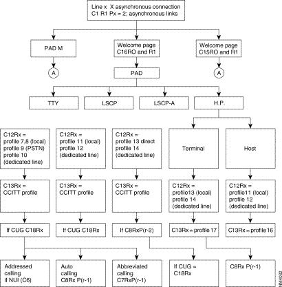 Configuration of an Asynchronous Line
The Welcome page for the device is defined in C15R0
The error correction procedure is a service offered by the VAP (Videotex Access Point) function. It corrects errors which are introduced by the network (PSTN) on the 1200 bauD-channel of the VAP-terminal (minitel) connection.
There are two types of error corrections. Which one is used depends on the mode of the modem
ECPN is activated (inactivated) on request of:
The ECPI is activated (inactivated) on request of:
The error threshold can be set with a configuration parameter: C12P90
The transmission time-out of a re-transmission request (ECPN) is set with configuration parameter, C12P91.
C1R1
<port #> 2 asynch type
C12R<port#> C12R<port#>
0 15 direct connection profile 0 35 PSTN (ECP)
16 PSTN connection profile
36 PSTN 75/1200 connection profile
C13R<port#> C13R<port#>
0 30 Videotext 0 46 PSTN videotext
P1 to P22
C6R0,R1 NUI/NUA table
C7R0-R3 mnemonic table
C8R0-R2 Automatic calling table
C12<port #>
P93 type of mnemonic
P90 Threshold error for ecp
P91 Threshold time-out nack for ecp
C15R0,R1 Welcome page
This function is used to connect over PSTN network a multistandard videotext terminal to a server via a gateway (groom).
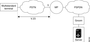
The mp is in charge of determining the identity of the terminal and establishing a logical connection with the groom giving the identity of the terminal.
During communication, the mp is transparent to X.29 indications. However it manages one X.29 message (before the communication takes place). This is the
ID request: TFI, ENQ, TER (seeC12RxP18,P19).
C1R1:
< port #> 2 Asynch type.
C12R<port #>: C13R<port#>
0 37 Multistandard connection profile 0 32 Pad-M
\QP18,P19 Identification phase
P38 Entry in C8R0,R4
C8R0 Automatic calling number to reach the groom
C8R4 Call retransmission timer*10s
Configuration of X28Plus is governed by optional software license (X.28+)
Used to connect an asynchronous device following Sprintnet and Telenet behavior.
If the user is set with Autospeed detection (so-called RAVC12RxP43), the user needs to enter the following sequence:
See also parameter 105-112 and 115-122 in Chapter 9, "Connection Profiles and Parameters."
Three possibilities are offered:
Addressed call case:
Call number-facilities*Call User Data
Call number: 1 to 10 digits.
Facilities: R for reverse charging
Gxx for Closed User Group
Nxxxxxx for NUI
Call User Data: Up to 12 characters.
These commands are accessible via an asynchronous terminal intended for the PAD to which it is directly connected.
| Commands | Functions | PAD Response |
|---|---|---|
STAT | Request for status of virtual call between PAD and terminal | ENGAGED = VC established FREE = VC not established |
LIB or CLR | Request to clear the call | LIB or CLR = call cleared |
PAR? Parameter numbers | Request for value of one or more parameters Example: PAR? 1, 2, 5 Note: To determine the values of all the parameters, type PAR? | Parameters followed by their value Example: PAR 1: 0.2 : 1.5 :1 |
SET? Parameter numbers: new values, | Modification of a value of one or more parameters Example: SET? 1: 0.2 : 0.4 : 3 | Parameters followed by their value Example: PAR 1: 0.2 : 1.5 : 1 |
PROF Profile Number | Choice of a standard profile available in the PAD |
|
RESET | Reset of a call |
|
INT | Transmission of an interrupt |
|
MSET? No. of new parameter values | Generation of PAD parameter positioning message | None or ERROR if refused by the remote |
mpAR Parameter number | Generation of PAD parameter positioning message, reading of parameter from remote | Parameters followed by their value |
RESET? No. of new parameter values | Generation of PAD parameter positioning message | None or ERROR if refused by the remote |
RPAR Parameter numbers | Generation of PAD parameter positioning message, reading pf parameter by the remote | Parameters followed by their value |
D or DISC | Clearing of VC |
|
CONT | Return to transfer |
|
TPAR? Parameter number | Request for a value of one or more TELENET parameters Note: To determine the value of all the parameters, type TPAR? | Parameters followed by their value Example: TPAR 1: 0.2 : 1.5 : 1 |
ID (up to 15 digits) | Identification of PSTN network user | ERROR if string is wrong: alpha characters, plus 15 digits |
IDOFF | PSTN network user identification facility not used |
|
C1R1
<port #>: 30 X.28+ type
C12r<port#>
0 27 direct
28 PSTN
29 dedicated line
C13R<port#>
0 ITU-T X.3 profile
C18r<port#> CUG.
C8R0,R4 automatic calling number.
C6R0,R1 NUI/NUA table.
C7R0-R3 Mnemonic table,
C16R0,R1 Welcome page.
![]()
![]()
![]()
![]()
![]()
![]()
![]()
![]()
Posted: Thu Jan 25 14:17:23 PST 2001
All contents are Copyright © 1992--2001 Cisco Systems, Inc. All rights reserved.
Important Notices and Privacy Statement.