|
|

On a FastPadmp there is no management of CIR, Be or Bc. There is no NNI, only UNI. LMI is available at this interface and can be UNI or NUI. Frame-Relay stacks that can be used on the FastPad are grouped within 3 acronyms which are FR-CE, FR-TE, FR-SE. In Fact it corresponds to the availability of the LMI.
Table 5-1 shows relations between acronyms, LMI and Frame-Relay stacks.
Acronyms | Frame-Relay Stacks | LMI |
FR-CE | FRA | UNI, NUI |
FR-TE | FRI, FRT, FRIP, FRSNA | UNI |
FR-SE | FRWS | Not available |
There are 4 parameters that can be used to generate congestion indication and that define the behavior to handle on reception of Frame-Relay frame with congestion bits set to one.
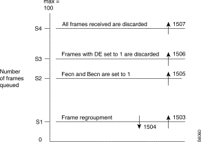
These parameters are S1, S2, S3 and S4 and define a number of frames. S4 must be higher than S3, S3 than S2, S2 than S1.
The maximum value that can be assigned is 100 and corresponds to VCqd. Table 5-1 shows the relation between these parameters and the IPX's acronyms.
Thresholds | Parameters | Default values | IPX's acronyms |
S1 | 36 | 1 | / |
S2 | 39 | 10 | ECNth |
S3 | 40 | 15 | DEth |
S4 | 41 | 20 | Vcqd |
S1: multi frame threshold.
S2: Becn,FEcn threshold, or ECNth.
S3: Selective discard threshold (Frame tagged with DE), or DEth.
S4: Total discard threshold, can be fixed up to 100, Vcqd for IPX.
The difference with the IPX is that these thresholds define a number of frame and not a number of bytes or percentage of queue (case of DEth).
Increasing thresholds result to increase the queue buffer for a PVC. As seen previously, a threshold defines a number of frames. To store a frame as for switching or processing one FastPad takes resources and it corresponds to a number of buffers in RAM.
So, in case of congestion problem, the FastPad indicates it with the corresponding outstanding events, it could be necessary to increase the thresholds. A typical example is a burst data traffic on a FRA port.
Following frame's size and the number of frames stored, more or less buffer will be used.
There is a flow control problem and the FastPad can store up to X frames(S4 set to X). If the frame's size is 4KB and X is 20, knowing that a buffer is 256 bytes. For 1 frame, 16 buffers are used so a total of 320 buffers for one PVC.
The number of free buffer is indicated within the statistic function. Change the thresholds' values only if this is necessary. For that check the outstanding events.
Before S1 there is no action. Frames are switched one for one.
When S1 is reached, according to the encapsulation type, several frames can be grouped within on packet. Outstanding event 1503 is generated when we pass over S1 and 1504 when we pass under S1.
When S2 is reached Becn and/or Fecn are set to one. Outstanding event 1505 is generated.
When S3 is reached, all incoming frames tagged with DE bit are discarded. Outstanding event 1506 is generated.
When S4 is reached, any incoming frame is discarded. Outstanding event 1507 is generated.

According to the Frame-Relay stack used, the way these thresholds are used is different. These thresholds are significant only for:
- FR-TE(FRT & FRIP)
- FR-CE(FRA)
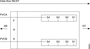
Sx thresholds are defined for the port but define a queue buffer for each PVC used on the FRA port. These parameters can be change if need be in Class 12 Rec X, which is the class where is defined the connection profile; X represents the port number.
FRA stack is never in congestion state towards the subscriber but only towards the network. It means that the policy is done at the entrance of the network at the ingress queue.
An encapsulation type using Multi Frame(MFR) must be used to carry transparently from end to end the congestion bits coming from the subscriber.
 From Subscriber Towards Network
First the FastPad will copy the bit header (DE, Becn, Fecn, CR) received from the subscriber within the SEP field used with the MFR encapsulation.
If the threshold S2 is reached the Fecn bit will be set to one.
If the threshold S3 is reached, frames received from the subscriber with DE bit set to one are discarded.
If the threshold S4 is reached all frames are discarded.
The Becn bit is never set by the FRA stack towards the network (Policy is done at the ingress queue at the remote site).
 From Network Towards the Subscriber
Fecn bit is never set to one by FRA.
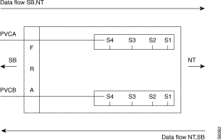
If when the FastPad is receiving frames from the network, there is a congestion in the opposite direction, so for the data flow SB, BT (at least S2 is reached); then the Becn bit will be set to one for frames send towards the subscriber.
Sx thresholds are defined for the Frame-Relay stack but defined a queue buffer for each PLL (a couple DLCI, Virtual line) used with this stack. These parameters can be change if need be in Class 30 Rec X, which is the class where are defined the FR-TE frame relay stack; X represents the recurrence number where is defined the stack.
These 2 FR-TE stacks are never in congestion state towards the network but only towards the subscriber. It means that the policy is done at the outgress queue.
An encapsulation type using Multi Frame(MFR) must be used to carry the congestion bits (case where the subscriber is a FRA).
First the FastPad will copy the bit header (DE, Becn, Fecn, CR) received from the subscriber within the SEP field used with the MFR encapsulation (case FRA).
Fecn bit is never set to one by FRT or FRIP.
If when the FastPad is receiving frames from the subscriber, there is a congestion in the opposite direction, (at least S2 is reached); then the Becn bit will be set to one for frames send towards the network.
Becn bit is never set to 1 by the FRT and FRIP stack (no congestion towards the subscriber).
If the threshold S2 is reached the Fecn bit will be set to one.
If the threshold S3 is reached, frames received from the subscriber with DE bit set to one are discarded.
If the threshold S4 is reached all frames are discarded.
There is no threshold. It means that Fecn and Becn are never set to 1. Except by the general threshold (see chp 8).
Since there is a flow control from end to end of the connection by using X.25 above Frame-Relay, all information frames from a LAP.B point of view, will be send within a frame-relay frame with DE bit set to 1.
Flow control for FRSNA follows the requirements of IBM's specifications.
On the network side where FRSNA is used, above frame relay there is LLC2. All information frames from a LLC2 point of view will be send by the FastPad with the De bit set to 1.
In case of congestion towards the subscriber (SDLC or QLLC) the flow control is done at the LLC2 level. The FastPad will send a RNR frame.
Becn and Fecn are never set by the FRSNA stack. There is no threshold.
In that case the FRSNA stack will send immediately a RR(LLC2 level). The DE bit is set to 0, since this is not an I frame. The network will be able to set up the Becn to 1 within the corresponding Frame-Relay frame to notify at the remote (source one) that there is a congestion.
In that case the FRSNA must follow a specific algorithm, according to IBM's recommendations.
It uses Tw (maximum transmit windows)
The principle is the following. On reception of a Frame-Relay frame with Becn set to 1, Ww is set to 1. It means that the FRSNA slows down immediately its own data flow, until reception of a Becn set to 0 the Ww will keep that value.
When the stack receives Nw frames with Becn set to 0, the Ww is increased by one. While this period, congestion one, the last I frame of current Ww is send with the poll bit set to one(LLC2 level).
The working windows(Ww) is increased up to the Tw value.
In Frame-Relay switching the FastPad passes transparently the congestion bits. It is not able to modify the DLCI header even in case of congestion.
Frames will be discarded only if a specific general threshold is reached (see chp 8).
Generally there is no need to change the General parameters' values.
These thresholds defined in Class 2 Rec 3 by parameters 0 and 2 represent a percentage of free memory(buffers) within the equipment. Buffers can be checked using the statistic function.
Parameter 0 or GS1 is: threshold where all frames are discarded in FR.
all I frames are discarded in X.25.
Parameter 2 or GS2 is: threshold where all frames will have Becn, Fecn set in FR-TE.
all Call Request packet are cleared in X25.
Default values for general thresholds are:
GS1= 7%
GS2=15%
When the percentage of free memory is lower than GS1, the FastPad will discard all frames whatever the interface.
When the percentage of free memory is between GS1 and GS2, the FastPad will set the congestion bits Becn and Fecn to one, for a FR-TE(FRI, FRIP, FRT, FRSNA) interface's type.
When the percentage of free memory is higher than GS2 nothing is done.
Each 10 frames received, a test is done on GS1.
For a FR-TE a test is realized on GS2 after each T391. It means that LMI must be activated to take into account the threshold GS2.
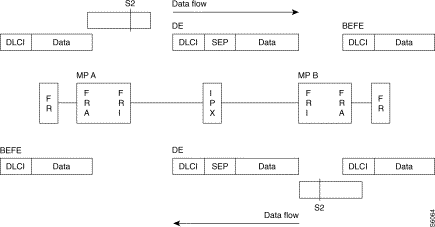
Hypothesis is done at the beginning that no congestion bit are set by the subscriber. Both following examples illustrate a congestion problem with the FRA stack.
The ingress queue buffer on MP A has reach the ECNth(S2) threshold. The FRA stack set the Fecn in the SEP field before forwarding the frame towards the network. The remote stack will copy values of the SEP field within the DLCI outgoing Frame-Relay frame. On the trunk the De bit is set in the DLCI header by the FRI stack.
 Simplex Traffic
On MP A outstanding event 1505 is generated.
In that case both MP's will set Fecn within the SEP field when sending the frame towards the network.
On reception from the network, both will copy the bit values within the outgoing Frame-Relay frame towards the subscriber and since there is a congestion towards the network will also turn on the Becn bit.
As in the previous example, on the trunk the De bit is set by FRI.

![]()
![]()
![]()
![]()
![]()
![]()
![]()
![]()
Posted: Thu Jan 25 13:57:31 PST 2001
All contents are Copyright © 1992--2001 Cisco Systems, Inc. All rights reserved.
Important Notices and Privacy Statement.